Page 528 of 1897
BR0KK-03
F09711N´m (kgf´cm, ft´lbf) : Specified torqueLower LH Panel Insert
Lower No. 1 Instrument Panel
Pedal Pad
No. 2 Heater to Register Duct
Clip
Parking Brake Cable
Parking Brake Pedal Assembly
61 (620, 45)
61 (620, 45)
Cushion
Parking Brake Switch
61 (620, 45)
BR-10
- BRAKEPARKING BRAKE PEDAL
1409 Author�: Date�:
2001 AVALON (RM808U)
COMPONENTS
Page 531 of 1897
BR151-01
F09746
F09747
- BRAKEPARKING BRAKE PEDAL
BR-1 1
1410 Author�: Date�:
2001 AVALON (RM808U)
REMOVAL
1. REMOVE LOWER NO. 1 INSTRUMENT PANEL, LOW-
ER LH PANEL INSERT AND NO. 2 HEATER TO REG-
ISTER DUCT (See page BO-87)
2. RELEASE PARKING BRAKE PEDAL
3. REMOVE PARKING BRAKE PEDAL ASSEMBLY
(a) Disconnect the parking brake switch connector.
(b) Remove the clip, and disconnect the parking brake cable.
(c) Remove the 3 nuts and parking brake pedal assembly.
Torque: 61 N´m (620 kgf´cm, 45 ft´lbf)
(d) Remove the parking brake switch and cushion from the
parking brake pedal assembly.
Page 552 of 1897
P20106
Terminal F CH-4
- CHARGINGCHARGING SYSTEM
1277 Author�: Date�:
2001 AVALON (RM808U)
If the voltmeter reading is more than standard voltage, replace
the voltage regulator.
If the voltmeter reading is less than standard voltage, check the
voltage regulator and generator as follows:
�With terminal F grounded, start the engine and
check the voltmeter reading of terminal B.
�If the voltmeter reading is more than standard volt-
age, replace the voltage regulator.
�If the voltmeter reading is less than standard volt-
age, check the generator.
9. INSPECT CHARGING CIRCUIT WITH LOAD
(a) With the engine running at 2,000 rpm, turn on the high
beam headlights and place the heater blower switch at
ºHIº.
(b) Check the reading on the ammeter.
Standard amperage: 30 A or more
If the ammeter reading is less than the standard amperage, re-
pair the generator.
HINT:
If the battery is fully charged, the indication will sometimes be
less than standard amperage.
Page 583 of 1897

ON-VEHICLE INSPECTION
1. REMOVE RADIATOR C")
CO09I-02
Z00570
Radiator Cap Tester
30° or More
Radiator Cap
P13014
Radiator Cap
Tester CO-14
- COOLINGRADIATOR
1207 Author�: Date�:
2001 AVALON (RM808U)
ON-VEHICLE INSPECTION
1. REMOVE RADIATOR CAP
CAUTION:
To avoid the danger of being burned, do not remove the ra-
diator cap while the engine and radiator are still hot, as fluid
and steam can be blow out under pressure.
2. INSPECT RADIATOR CAP
NOTICE:
�If the radiator cap has contaminations, always rinse
it with water.
�When performing steps (a) and (b) below, keep the ra-
diator cap tester at an angle of over 30° above the hor-
izontal.
�Before using a radiator cap tester, wet the relief valve
and pressure valve with engine coolant or water.
(a) Using a radiator cap tester, slowly pump the tester and
check that air is coming from the vacuum valve.
Pump speed: 1 push/(3 seconds or more)
NOTICE:
Push the pump at a constant speed.
If air is not coming from the vacuum valve, replace the radiator
cap.
(b) Pump the tester and measure the relief valve opening
pressure.
Pump speed: 1 push within 1 second
NOTICE:
This pump speed is for the first pump only (in order to close
the vacuum valve). After this, the pump speed can be re-
duced.
Standard opening pressure:
83 - 113 kPa (0.85 - 1.15 kgf/cm
2, 12.1 - 16.4 psi)
Minimum opening pressure:
69 kPa (0.7 kgf/cm
2, 10.0 psi)
HINT:
Use the tester's maximum reading as the opening pressure.
If the opening pressure is less than minimum, replace the radia-
tor cap.
3. INSPECT COOLING SYSTEM FOR LEAKS
(a) Fill the radiator with coolant, and attach a radiator cap tes-
ter.
(b) Warm up the engine.
(c) Pump it to 127 kPa (1.3 kgf/cm
2, 18.5 psi), and check that
the pressure does not drop.
If the pressure drops, check the hoses, radiator or water pump
for leaks. If no external leaks are found, check the heater core,
cylinder block and cylinder head.
4. REINSTALL RADIATOR CAP
Page 588 of 1897
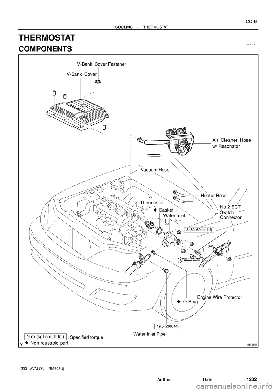
CO02Q-03
B09035
V-Bank Cover
Air Cleaner Hose
w/ Resonator
Engine Wire Protector
Thermostat
� Gasket
Water Inlet
Water Inlet PipeN´m (kgf´cm, ft´lbf)
: Specified torque
� O-Ring
No.2 ECT
Switch
Connector
8 (80, 69 in.´lbf)
19.5 (200, 14)
� Non-reusable part
Vacuum Hose
Heater Hose
V-Bank Cover Fastener
- COOLINGTHERMOSTAT
CO-9
1202 Author�: Date�:
2001 AVALON (RM808U)
THERMOSTAT
COMPONENTS
Page 590 of 1897

INSTALLATION
1. PLACE THERMOSTAT IN WATER PUMP
(a) Install a new gasket on to the th")
CO02T-03
B04153Stud BoltJiggle Valve
15°15°
CO-12
- COOLINGTHERMOSTAT
1205 Author�: Date�:
2001 AVALON (RM808U)
INSTALLATION
1. PLACE THERMOSTAT IN WATER PUMP
(a) Install a new gasket on to the thermostat.
(b) Align the thermostat jiggle valve with the upper stud bolt,
and insert the thermostat in the water inlet housing.
HINT:
The jiggle valve may be set within 15° of either side of the pre-
scribed position.
2. INSTALL WATER INLET
Install the water inlet with the 3 nuts.
Torque: 8 N´m (80 kgf´cm, 69 in.´lbf)
3. INSTALL WATER INLET PIPE
(a) Install a new O-ring to the water inlet pipe.
(b) Apply soapy water to the O-ring.
(c) Connect the water inlet pipe to the water inlet.
(d) Install the bolt holding the water inlet pipe to the LH cylin-
der head.
Torque: 19.5 N´m (200 kgf´cm, 14 ft´lbf)
4. INSTALL ENGINE WIRE PROTECTOR
5. CONNECT NO.2 ECT SWITCH CONNECTOR
6. CONNECT HEATER HOSES
7. REINSTALL AIR CLEANER HOSE WITH RESONATOR
8. INSTALL V-BANK COVER
(a) Using 5 mm hexagon wrench, install the V-bank cover
with the 3 cap nuts.
(b) Press down the V-bank cover fastener.
9. FILL WITH ENGINE COOLANT
10. START ENGINE AND CHECK FOR LEAKS
11. RECHECK ENGINE COOLANT LEVEL
Page 591 of 1897

REMOVAL
HINT:
Removal of the thermostat would have an adverse effect, cau")
CO0SW-02
A10518
5 mm
Hexagon
Wrench
B08906
B06725
B04150
CO-10
- COOLINGTHERMOSTAT
1203 Author�: Date�:
2001 AVALON (RM808U)
REMOVAL
HINT:
Removal of the thermostat would have an adverse effect, caus-
ing a lowering of cooling efficiency. Do not remove the thermo-
stat, even if the engine tends to overheat.
1. DRAIN ENGINE COOLANT
2. REMOVE V-BANK COVER
(a) Using a 5 mm hexagon wrench, remove the 3 cap nuts.
(b) Loosen the V-bank cover fastener counterclockwise.
(c) Remove the V-bank cover.
3. WARM UP ENGINE
Allow the engine to warm up to normal operating temperature.
4. REMOVE AIR CLEANER HOSE WITH RESONATOR
5. DISCONNECT HEATER HOSES
6. DISCONNECT NO.2 ECT SWITCH CONNECTOR
7. DISCONNECT ENGINE WIRE PROTECTOR FROM
WATER INLET AND RH CYLINDER HEAD
Remove the nut and disconnect the clamp, and disconnect the
engine wire protector from the water inlet and cylinder head.
8. DISCONNECT WATER INLET PIPE FROM WATER IN-
LET AND LH CYLINDER HEAD
(a) Remove the bolt, and disconnect the inlet pipe from the
water inlet.
(b) Remove the O-ring from the inlet pipe.
9. REMOVE WATER INLET AND THERMOSTAT
(a) Remove the 3 nuts, water inlet and thermostat.
(b) Remove the gasket from the thermostat.
Page 927 of 1897

Platinum
Electrode
Heater
A/F Sensor Voltage
Air-Fuel Ratio
(V)
2.6 4.0
3.8
3.6
3.4
3.2
3.0
2.8
2.4
12 13 14")
A00477
Atmosphere
Cover
Exhaust GasPlatinum
Electrode
Solid Electrolyte
(Zirconia Element)
Platinum
Electrode
Heater
A/F Sensor Voltage
Air-Fuel Ratio
(V)
2.6 4.0
3.8
3.6
3.4
3.2
3.0
2.8
2.4
12 13 14 15 16 17 18
Coating (Ceramic)
ECM Monitored
19
Housing
- DIAGNOSTICSENGINE
DI-43
199 Author�: Date�:
2001 AVALON (RM808U)
DTC P0125 Insufficient Coolant Temp. for Closed Loop
Fuel Control
CIRCUIT DESCRIPTION
To obtain a high purification rate for the CO, HC and NOx components of the exhaust gas, a three-way cata-
lytic converter is used, but for the most efficient use of the three-way catalytic converter, the air-fuel ratio
must be precisely controlled so that it is always close to the stoichiometric air-fuel ratio.
The A/F sensor has the characteristic that provides output voltage* approximately proportional to the exist-
ing air-fuel ratio. The A/F sensor output voltage* is used to provide feedback for the ECM to control the air-
fuel ratio.
By the A/F sensor output, the ECM can determine the deviation amount from the stoichiometric air-fuel ratio
and control the proper injection time immediately. If the A/F sensor is malfunctioning, ECM is unable to per-
form accurate air-fuel ratio control.
The A/F sensor is equipped with a heater which heats the zirconia element. The heater is controlled by the
ECM. When the intake air volume is low (the temp. of the exhaust gas is low), current flows to the heater
to heat the sensor for accurate oxygen concentration detection.
*: The voltage value changes at the inside of the ECM only.
DTC No.DTC Detecting ConditionTrouble Area
P0125
After engine is warmed up, A/F sensor output* does not
change when conditions (a), (b), (c) and (d) continue for at
least 1.5 min:
*: Output value changes at inside of the ECM only
(a) Engine speed: 1,500 rpm or more
(b) Vehicle speed: 40 - 100 km/h (25 - 62 mph)
(c) Throttle valve is not fully closed
(d) 140 sec. or more after starting engine�Open or short in A/F sensor (bank 1, 2 sensor 1) circuit
�A/F sensor (bank 1, 2 sensor 1)
�Air inducation system
�Fuel pressure
�Injector
�Gas leakage on exhaust sytem
�ECM
HINT:
�After confirming DTC P0125, use the OBD II scan tool or TOYOTA hand-held tester to confirm voltage
output of the A/F sensor (bank 1, 2 sensor 1) from the CURRENT DATA.
�The ECM controls the voltage of the AFR+, AFL+, AFR- and AFL- terminals of the ECM to the fixed
voltage. Therefore, it is impossible to confirm the A/F sensor output voltage without the OBDII scan
tool or TOYOTA hand-held tester.
DI07M-14
 : Specified torqueLower LH Panel Insert
Lower No. 1 Instrument Panel
Pedal Pad
No. 2 Heater to Register Duct
Clip
Parking Brake Cable
Parking Brake Pedal Assembl")