Page 1226 of 1897
DTC No.
(See Page)
Detection ItemTrouble AreaSRS
Warning Light
B0117/45
(DI-412)�Short in side squib (LH)")
DI-356
- DIAGNOSTICSSUPPLEMENTAL RESTRAINT SYSTEM
512 Author�: Date�:
2001 AVALON (RM808U)DTC No.
(See Page)
Detection ItemTrouble AreaSRS
Warning Light
B0117/45
(DI-412)�Short in side squib (LH) circuit
(to ground)�Side airbag assembly LH (squib)
�Airbag sensor assembly
�Wire harness
Blink
B0118/46
(DI-415)�Short in side squib (LH) circuit
(to B+)�Side airbag assembly LH (squib)
�Airbag sensor assembly
�Wire harness
Blink
B0130/63
(DI-418)�Short in P/T squib (RH) circuit�Seat belt pretensioner RH (squib)
�Airbag sensor assembly
�Wire harness
Blink
B0131/64
(DI-422)�Open in P/T squib (RH) circuit�Seat belt pretensioner RH (squib)
�Airbag sensor assembly
�Wire harness
Blink
B0132/61
(DI-425)�Short in P/T squib (RH) circuit
(to ground)�Seat belt pretensioner RH (squib)
�Airbag sensor assembly
�Wire harness
Blink
B0133/62
(DI-428)�Short in P/T squib (RH) circuit
(to B+)�Seat belt pretensioner RH (squib)
�Airbag sensor assembly
�Wire harness
Blink
B0135/73
(DI-431)�Short in P/T squib (LH) circuit�Seat belt pretensioner LH (squib)
�Airbag sensor assembly
�Wire harness
Blink
B0136/74
(DI-435)�Open in P/T squib (LH) circuit�Seat belt pretensioner LH (squib)
�Airbag sensor assembly
�Wire harness
Blink
B0137/71
(DI-438)�Short in P/T squib (LH) circuit
(to ground)�Seat belt pretensioner LH (squib)
�Airbag sensor assembly
�Wire harness
Blink
B0138/72
(DI-441)�Short in P/T squib (LH) circuit
(to B+)�Seat belt pretensioner LH (squib)
�Airbag sensor assembly
�Wire harness
Blink
B1100/31
(DI-444)�Airbag sensor assembly malfunction�Airbag sensor assemblyON
B1140/32
(DI-446)�Side airbag sensor assembly (RH)
malfunction�Side airbag sensor assembly (RH)
�Airbag sensor assembly
�Wire harness
Blink
B1141/33
(DI-454)�Side airbag sensor assembly (LH)
malfunction�Side airbag sensor assembly (LH)
�Airbag sensor assembly
�Wire harness
Blink
B1156/B1157/
15
(DI-462)�Front airbag sensor (RH) malfunction�Front airbag sensor (RH)
�Airbag sensor assembly
�Wire harness
ON
B1158/B1159/
16
(DI-467)�Front airbag sensor (LH) malfunction�Front airbag sensor (LH)
�Airbag sensor assembly
�Instrument panel wire harness
�Engine room main wire harness
ON
Nl�System normal-OFFNormal
(DI-475)�Voltage source drop�Battery
�Airbag sensor assemblyON
Page 1287 of 1897
EM-2
- ENGINE MECHANICALCO/HC
986 Author�: Date�:
2001 AVALON (RM808U)
If the CO/HC concentration does not comply with regulations,
troubleshoot in the order given below.
See the table below for possible causes, and then inspect and
correct the applicable causes if necessary.
COHCProblemsCauses
NormalHighRough idle3. Faulty ignitions:
�Incorrect timing
�Fouled, shorted or improperly gapped plugs
4. Incorrect valve clearance
5. Leaky intake and exhaust valves
6. Leaky cylinders
LowHighRough idle
(Fluctuating HC reading)1. Vacuum leaks:
�PCV hoses
�Intake manifold
�Air intake chamber
�Throttle Body
�IAC valve
�Brake booster line
2. Lean mixture causing misfire
HighHighRough idle
(Black smoke from exhaust)1. Restricted air filter
2. Plugged PCV valve
3. Faulty SFI systems:
�Faulty pressure regulator
�Defective ECT sensor
�Faulty ECM
�Faulty injectors
�Faulty throttle position sensor
�Faulty MAF meter
Page 1289 of 1897

No.2 Idler Pulley Bracket
Water Seal Plate
Engine Coolant
Drain Union
Oil Filter")
EM04B-04
A10521
Knock Sensor Connector
Engine Wire Band
Engine WireKnock Sensor
Water Inlet Housing
(With Water Inlet)
No.2 Idler Pulley Bracket
Water Seal Plate
Engine Coolant
Drain Union
Oil Filter Union
Oil Filter � Gasket
Cylinder Block
Side Cover
� Gasket
Water Pump
� Crankshaft
Front Oil Seal
Crankshaft
Position Sensor
Connector� Oil Pressure
Switch
Oil Pressure Switch
Connector
A/C Compressor
Housing Bracket
No.1 Oil Pan
x 17 Oil Pump
� Gasket
� Gasket
Engine WireGenerator
Drain Plugx 10No.2 Oil Pan Oil Strainer
� Non-reusable part
N´m (kgf´cm, ft´lbf): Specified torque
Precoated part �
8 (80, 69 in.´lbf)
8 (80, 69 in.´lbf)
10 mm Head 8 (80, 69 in.´lbf)
12 mm Head 19.5 (200, 14)
10 mm Head 8 (80, 69 in.´lbf)
12 mm Head 19.5 (200, 14)
45 (460, 33)
8 (80, 69 in.´lbf)
9 (90, 78 in.´lbf)
x 8
8 (80, 69 in.´lbf)
28 (290, 21)
�
18 (180, 13)
25 (250, 18)
39 (400, 29)
No.2 ECT Switch
Connector
� O-Ring
x 9
19.5 (200, 14)
- ENGINE MECHANICALCYLINDER BLOCK
EM-81
1065 Author�: Date�:
2001 AVALON (RM808U)
CYLINDER BLOCK
COMPONENTS
Page 1291 of 1897

DISASSEMBLY
1. REMOVE DRIVE PLATE
Remove the 8 bolts, rear plate, drive plate a")
A05415
EM0ZN-02
S04921
A05252
P18761
- ENGINE MECHANICALCYLINDER BLOCK
EM-83
1067 Author�: Date�:
2001 AVALON (RM808U)
DISASSEMBLY
1. REMOVE DRIVE PLATE
Remove the 8 bolts, rear plate, drive plate and front spacer.
2. INSTALL ENGINE TO ENGINE STAND FOR DIS-
ASSEMBLY
3. REMOVE TIMING BELT AND PULLEYS
(See page EM-15)
4. REMOVE CYLINDER HEAD (See page EM-31)
5. DISCONNECT CRANKSHAFT POSITION SENSOR
CONNECTOR
6. DISCONNECT OIL PRESSURE SWITCH CONNECTOR
7. DISCONNECT OIL LEVEL SENSOR CONNECTOR
8. REMOVE ENGINE WIRE
(a) Disconnect the 2 wire clamps from the wire brackets.
(b) Remove the 2 bolts and nut, and disconnect the engine
wire.
9. REMOVE GENERATOR, ADJUSTING BAR AND
BRACKET ASSEMBLY
Remove the 3 nuts, the generator, adjusting bar and bracket as-
sembly.
10. REMOVE OIL PRESSURE SWITCH
(See page LU-1)
11. REMOVE A/C COMPRESSOR HOUSING BRACKET
Remove the 2 bolts and compressor housing bracket.
12. REMOVE NO.2 IDLER PULLEY BRACKET
Remove the 2 bolts and idler pulley bracket.
Page 1292 of 1897

13.")
P12389
SST
A05253
P18763
WaterSeal
Plate
Oil Filter
Union
12 mm
Hexagon
Wrench
Coolant
Drain
Union
A02010
P12508
EM-84
- ENGINE MECHANICALCYLINDER BLOCK
1068 Author�: Date�:
2001 AVALON (RM808U)
13. REMOVE KNOCK SENSORS
(a) Disconnect the 2 knock sensor connectors.
(b) Using SST, remove the 2 knock sensors.
SST 09816-30010
14. REMOVE WATER INLET HOUSING
(a) Remove the engine wire band.
(b) Disconnect the engine wire clamp from the bracket.
(c) Remove the 8 bolts, 2 nuts and water inlet housing.
15. REMOVE WATER PUMP (See page CO-6)
16. REMOVE NO.2 OIL PAN (See page LU-9)
17. REMOVE OIL STRAINER (See page LU-3)
18. REMOVE NO.1 OIL PAN (See page LU-3)
19. REMOVE OIL PUMP (See page LU-9)
20. REMOVE OIL FILTER (See page LU-3)
21. REMOVE OIL FILTER UNION
Using a 12 mm hexagon wrench, remove the oil filter union.
22. REMOVE WATER SEAL PLATE
Remove the 2 nuts and seal plate.
23. REMOVE ENGINE COOLANT DRAIN UNION
24. REMOVE CYLINDER BLOCK SIDE COVER
Remove the 3 bolts, 2 nuts, cylinder block side cover and gas-
ket.
25. REMOVE REAR OIL SEAL RETAINER
(a) Remove the 6 bolts.
(b) Using a screwdriver, remove the oil seal retainer by prying
the portions between the oil seal retainer and main bear-
ing cap.
Page 1314 of 1897

�Using a non-residue solvent, clean both sealing
sur")
P12909
Seal Width 3 - 5 mm
A05253410
2
5
7
93
1
6
8
P12389
SST EM-108
- ENGINE MECHANICALCYLINDER BLOCK
1092 Author�: Date�:
2001 AVALON (RM808U)
�Using a non-residue solvent, clean both sealing
surfaces.
(b) Apply seal packing to the water inlet housing as shown in
the illustration.
Seal packing: Part No. 08826-00100 or equivalent
�Install a nozzle that has been cut to a 3 - 5 mm (0.12
- 0.20 in.) opening.
HINT:
Avoid applying an excessive amount to the surface.
�Parts must be assembled within 3 minutes of ap-
plication. Otherwise the material must be removed
and reapplied.
�Immediately remove nozzle from the tube and rein-
stall cap.
(c) Install the water inlet housing with the 8 bolts and 2 nuts.
Uniformly tighten the bolts and nuts in several passes and
in the sequence shown.
Torque: 8 N´m (80 kgf´cm, 69 in.´lbf)
(d) Connect the No.2 ECT switch connector.
(e) Connect the engine wire clamp to the water inlet.
(f) Install the engine wire band.
(g) Install the engine wire clamp.
27. INSTALL KNOCK SENSORS
(a) Using SST, install the 2 knock sensors.
SST 09816-30010
Torque: 39 N´m (400 kgf´cm, 29 ft´lbf)
(b) Connect the 2 knock sensor connectors.
28. INSTALL NO.2 IDLER PULLEY BRACKET
Torque: 28 N´m (290 kgf´cm, 21 ft´lbf)
29. INSTALL A/C COMPRESSOR HOUSING BRACKET
Torque: 25 N´m (250 kgf´cm, 18 ft´lbf)
Page 1315 of 1897
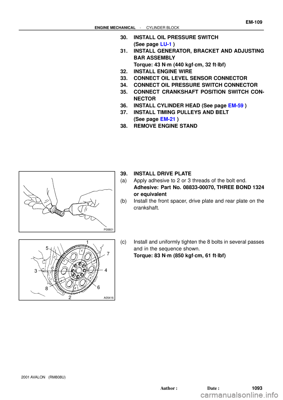
P00601
A05416
1
2 34 5
67
8
- ENGINE MECHANICALCYLINDER BLOCK
EM-109
1093 Author�: Date�:
2001 AVALON (RM808U)
30. INSTALL OIL PRESSURE SWITCH
(See page LU-1)
31. INSTALL GENERATOR, BRACKET AND ADJUSTING
BAR ASSEMBLY
Torque: 43 N´m (440 kgf´cm, 32 ft´lbf)
32. INSTALL ENGINE WIRE
33. CONNECT OIL LEVEL SENSOR CONNECTOR
34. CONNECT OIL PRESSURE SWITCH CONNECTOR
35. CONNECT CRANKSHAFT POSITION SWITCH CON-
NECTOR
36. INSTALL CYLINDER HEAD (See page EM-59)
37. INSTALL TIMING PULLEYS AND BELT
(See page EM-21)
38. REMOVE ENGINE STAND
39. INSTALL DRIVE PLATE
(a) Apply adhesive to 2 or 3 threads of the bolt end.
Adhesive: Part No. 08833-00070, THREE BOND 1324
or equivalent
(b) Install the front spacer, drive plate and rear plate on the
crankshaft.
(c) Install and uniformly tighten the 8 bolts in several passes
and in the sequence shown.
Torque: 83 N´m (850 kgf´cm, 61 ft´lbf)
Page 1319 of 1897
Water Bypass Hose
A10522
PS Pressure Tube
Throttle Body Bracket
Engine WireThrottle Position
Sensor Connector
Vacuum Hose Brake Booster
39 (400,29)
IAC Valve
Connector
Accelerator Cable
Purge Hose
Hose Vacuum
�Gasket
VSV Connector for No.2 ACIS
Engine Coolant
Reservoir Hose
43 (440,32)
ECT Sender
Gauge Connector
ECT Sensor
Connector
Grand Strap
Connector
15 (150,11)
Water Outlet
15 (150,11)
Water Bypass
Hose
Upper Radiator
HoseFuel Inlet Hose
Injector Connector Intake Manifold
Assembly
�Retainer
Heater Hose
�GasketIgnition Coil
Connector
� Non-reusable part: Specified torque
N´m (kgf´cm, ft´lbf)
19.5 (200, 14)
No.1 Engine
Hanger
VSV Connector for
EVAP
Ground Cable
PCV Hose Ground Cable
Air Intake Chamber
Assembly
� Gasket
Spark PlugIgnition Coil
Ground Strap
DLC1
Gasket
Fuel Hose Clamp
VSV Connector
for No.1 ACIS
Throttle Cable
- ENGINE MECHANICALCYLINDER HEAD
EM-27
1011 Author�: Date�:
2001 AVALON (RM808U)


IAC Valve
Connector
Accelerator Cable
Purge Hose
Hos")