Page 276 of 1897
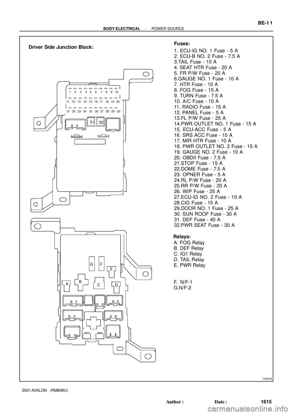
I12518
1. ECU-IG NO. 1 Fuse - 5 A
2. ECU-B NO. 2 Fuse - 7.5 A
3.TAIL Fuse - 10 A
4. SEAT HTR Fuse - 20 A
5. FR P/W Fuse - 20 A
6.GAUGE NO. 1 Fuse - 10 A
7. HTR Fuse - 10 A
8. FOG Fuse - 15 A
9. TURN Fuse - 7.5 A
10. A/C Fuse - 10 A
11. RADIO Fuse - 15 A
12. PANEL Fuse - 5 A
13.FL P/W Fuse - 25 A
14.PWR OUTLET NO. 1 Fuse - 15 A
15. ECU-ACC Fuse - 5 A
16. SRS ACC Fuse - 10 A
17. MIR HTR Fuse - 10 A
18. PWR OUTLET NO. 2 Fuse - 15 A
19. GAUGE NO. 2 Fuse - 10 A
20. OBDII Fuse - 7.5 A
21.STOP Fuse - 15 A
22.DOME Fuse - 7.5 A
23. OPNER Fuse - 5 A
24.RL P/W Fuse - 20 A
25.RR P/W Fuse - 20 A
26. WIP Fuse - 25 A
27.ECU-IG NO. 2 Fuse - 10 A
28.CIG Fuse - 15 A
29.DOOR NO. 1 Fuse - 25 A
30. SUN ROOF Fuse - 30 A
31. DEF Fuse - 40 A
32.PWR SEAT Fuse - 30 A Fuses:
Driver Side Junction Block:
2526
31
32
1234568
21222324
7910
27282930
Relays:
A. FOG Relay
B. DEF Relay
C. IG1 Relay
D. TAIL Relay
E. PWR Relay
F. N/F-1
G.N/F-2
AB
C
D E F G
11121314151718161920
- BODY ELECTRICALPOWER SOURCE
BE-1 1
1615 Author�: Date�:
2001 AVALON (RM808U)
Page 304 of 1897
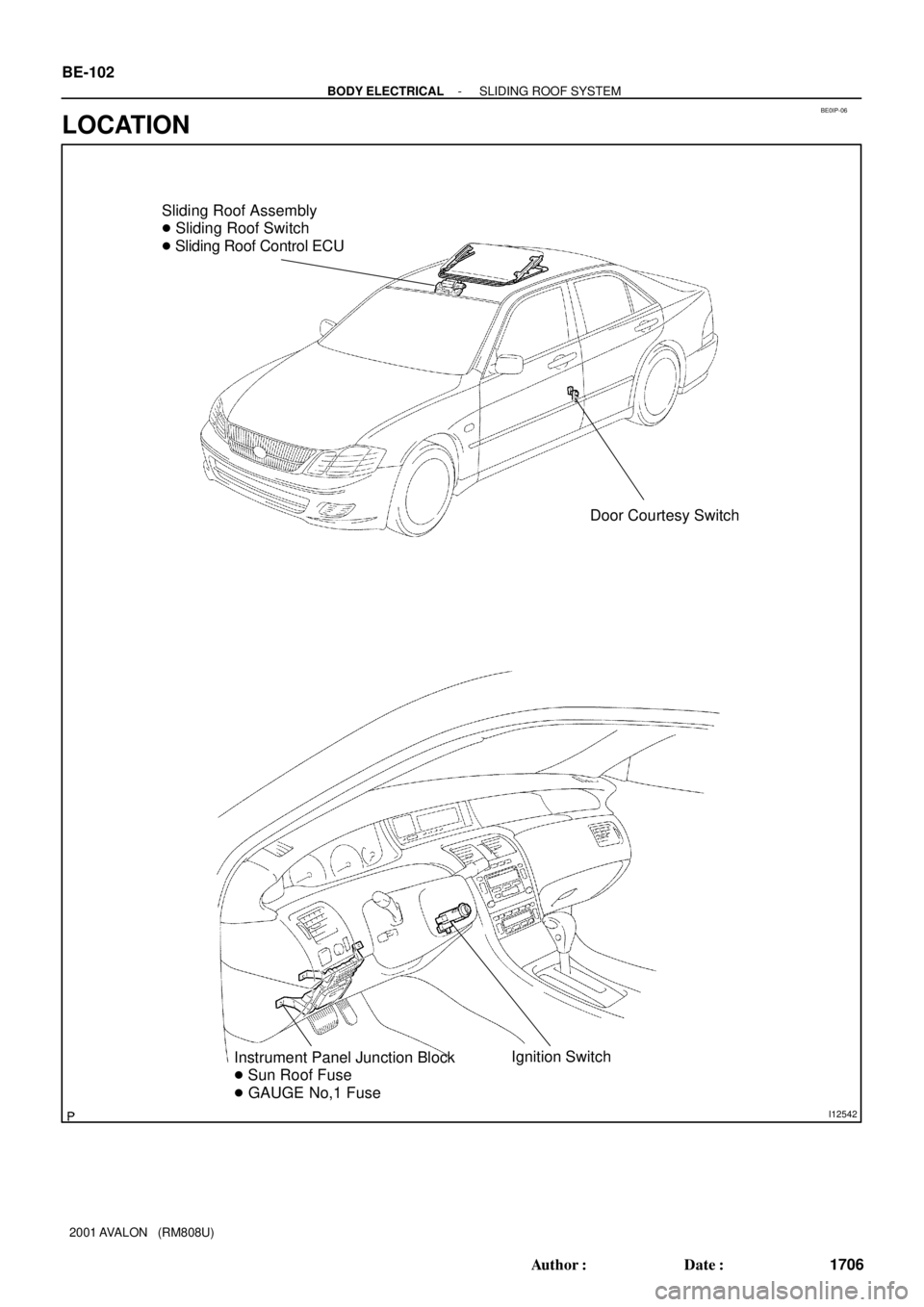
BE0IP-06
I12542
Instrument Panel Junction Block
� Sun Roof Fuse
� GAUGE No,1 FuseIgnition Switch Sliding Roof Assembly
� Sliding Roof Switch
� Sliding Roof Control ECU
Door Courtesy Switch
BE-102
- BODY ELECTRICALSLIDING ROOF SYSTEM
1706 Author�: Date�:
2001 AVALON (RM808U)
LOCATION
Page 311 of 1897
- BODY ELECTRICALTROUBLESHOOTING
BE-7
1611 Author�: Date�:
2001 AVALON (RM808U)
WIRELESS DOOR LOCK CONTROL SYSTEM
This system uses the multiplex communication system, so check diagnosis system of the multiplex commu-
nication system before checking the body control system.
Some functions of wireless door lock control system do not operate.
HINT:
�Troubleshooting of the wireless door lock control system is based on the premise that the door lock
control system is operating normally. Accordingly, before troubleshooting the wireless door lock control
system, first make certain that the door lock control system is operating normally.
�If the trouble still reappears even though there are no abnormalities in any of the other circuits, then
check and replace the Wireless Door Lock Control Receiver as the last step.
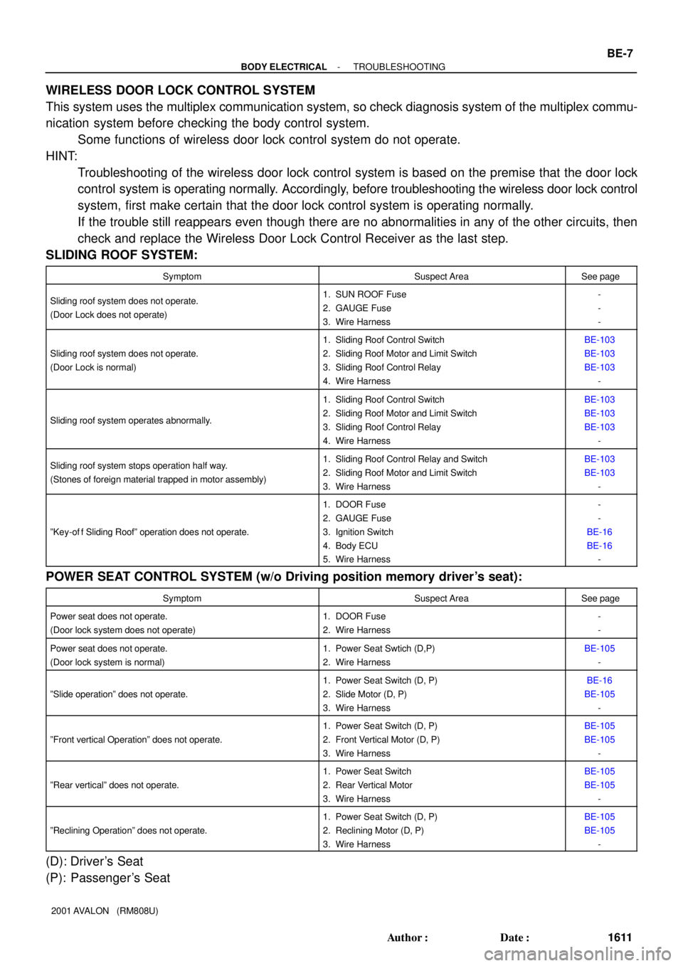
SLIDING ROOF SYSTEM:
SymptomSuspect AreaSee page
Sliding roof system does not operate.
(Door Lock does not operate)1. SUN ROOF Fuse
2. GAUGE Fuse
3. Wire Harness-
-
-
Sliding roof system does not operate.
(Door Lock is normal)
1. Sliding Roof Control Switch
2. Sliding Roof Motor and Limit Switch
3. Sliding Roof Control Relay
4. Wire HarnessBE-103
BE-103
BE-103
-
Sliding roof system operates abnormally.
1. Sliding Roof Control Switch
2. Sliding Roof Motor and Limit Switch
3. Sliding Roof Control Relay
4. Wire HarnessBE-103
BE-103
BE-103
-
Sliding roof system stops operation half way.
(Stones of foreign material trapped in motor assembly)1. Sliding Roof Control Relay and Switch
2. Sliding Roof Motor and Limit Switch
3. Wire HarnessBE-103
BE-103
-
ºKey-of f Sliding Roofº operation does not operate.
1. DOOR Fuse
2. GAUGE Fuse
3. Ignition Switch
4. Body ECU
5. Wire Harness-
-
BE-16
BE-16
-
POWER SEAT CONTROL SYSTEM (w/o Driving position memory driver's seat):
SymptomSuspect AreaSee page
Power seat does not operate.
(Door lock system does not operate)1. DOOR Fuse
2. Wire Harness-
-
Power seat does not operate.
(Door lock system is normal)1. Power Seat Swtich (D,P)
2. Wire HarnessBE-105
-
ºSlide operationº does not operate.
1. Power Seat Switch (D, P)
2. Slide Motor (D, P)
3. Wire HarnessBE-16
BE-105
-
ºFront vertical Operationº does not operate.
1. Power Seat Switch (D, P)
2. Front Vertical Motor (D, P)
3. Wire HarnessBE-105
BE-105
-
ºRear verticalº does not operate.
1. Power Seat Switch
2. Rear Vertical Motor
3. Wire HarnessBE-105
BE-105
-
ºReclining Operationº does not operate.
1. Power Seat Switch (D, P)
2. Reclining Motor (D, P)
3. Wire HarnessBE-105
BE-105
-
(D): Driver's Seat
(P): Passenger's Seat
Page 444 of 1897
BO2PZ-01
H12201
Roof Headlining
Roof Side Inner Garnish
Front Seat Outer
Belt Floor Anchor
Front Door
Opening Trim Assist Grip
w/ Rear personal light:
Rear Personal Light
Roof
Console
Box
Map Light Lens
Assist Grip
Sun Visor
Holder
Front Pillar Garnish
Front Door Scuff
Inside Plate
Center Pillar GarnishLensRoom Light
RH Rear Seat Inner
with Center Belt
Rear Door
Opening Trim
Lower Center
Pillar GarnishInside Rear Door
Scuff Plate
Rear Seatback
LH Rear Seat Inner
with Center Belt
Rear Seat Cushion
w/ Sliding roof:
Roof HeadliningSliding Roof
Opening Trim
41 (420, 30)
Lap Belt Outer Anchor Cover
41 (420, 30)
18 (185, 13)
18 (185, 13)
41 (420, 30)
: Specified torqueN´m (kgf´cm, ft´lbf)Cover
Cover
BO-98
- BODYROOF HEADLINING
1883 Author�: Date�:
2001 AVALON (RM808U)
ROOF HEADLINING
COMPONENTS
Page 448 of 1897
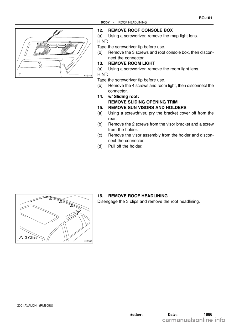
H12144
H121623 Clips
- BODYROOF HEADLINING
BO-101
1886 Author�: Date�:
2001 AVALON (RM808U)
12. REMOVE ROOF CONSOLE BOX
(a) Using a screwdriver, remove the map light lens.
HINT:
Tape the screwdriver tip before use.
(b) Remove the 3 screws and roof console box, then discon-
nect the connector.
13. REMOVE ROOM LIGHT
(a) Using a screwdriver, remove the room light lens.
HINT:
Tape the screwdriver tip before use.
(b) Remove the 4 screws and room light, then disconnect the
connector.
14. w/ Sliding roof:
REMOVE SLIDING OPENING TRIM
15. REMOVE SUN VISORS AND HOLDERS
(a) Using a screwdriver, pry the bracket cover off from the
rear.
(b) Remove the 2 screws from the visor bracket and a screw
from the holder.
(c) Remove the visor assembly from the holder and discon-
nect the connector.
(d) Pull off the holder.
16. REMOVE ROOF HEADLINING
Disengage the 3 clips and remove the roof headlining.
Page 465 of 1897
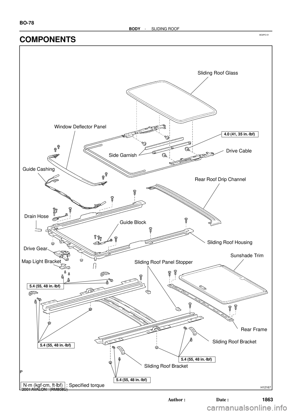
BO2PO-01
H12167
Sliding Roof Glass
Drive Cable
Side Garnish
Rear Roof Drip Channel
Guide Block Guide CashingWindow Deflector Panel
Drive Gear
Map Light Bracket
Sliding Roof Panel StopperSliding Roof Housing
Sunshade Trim
Rear Frame
Sliding Roof Bracket
Sliding Roof Bracket
5.4 (55, 48 in.´lbf)
5.4 (55, 48 in.´lbf)
5.4 (55, 48 in.´lbf)
5.4 (55, 48 in.´lbf)
4.0 (41, 35 in.´lbf)
N´m (kgf´cm, ft´lbf)
: Specified torque Drain Hose
BO-78
- BODYSLIDING ROOF
1863 Author�: Date�:
2001 AVALON (RM808U)
COMPONENTS
Page 466 of 1897
BO2PQ-01
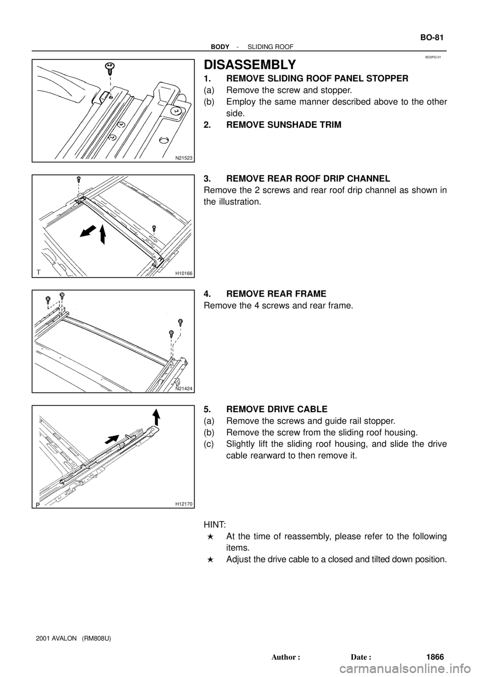
N21523
H10166
N21424
H12170
- BODYSLIDING ROOF
BO-81
1866 Author�: Date�:
2001 AVALON (RM808U)
DISASSEMBLY
1. REMOVE SLIDING ROOF PANEL STOPPER
(a) Remove the screw and stopper.
(b) Employ the same manner described above to the other
side.
2. REMOVE SUNSHADE TRIM
3. REMOVE REAR ROOF DRIP CHANNEL
Remove the 2 screws and rear roof drip channel as shown in
the illustration.
4. REMOVE REAR FRAME
Remove the 4 screws and rear frame.
5. REMOVE DRIVE CABLE
(a) Remove the screws and guide rail stopper.
(b) Remove the screw from the sliding roof housing.
(c) Slightly lift the sliding roof housing, and slide the drive
cable rearward to then remove it.
HINT:
�At the time of reassembly, please refer to the following
items.
�Adjust the drive cable to a closed and tilted down position.
Page 476 of 1897
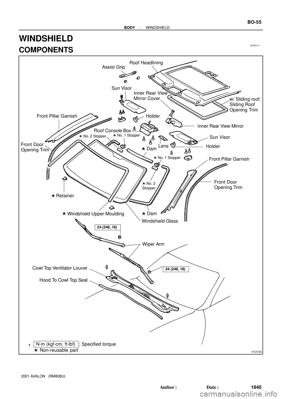
BO2PE-01
H12155
: Specified torqueN´m (kgf´cm, ft´lbf)
� Non-reusable partHood To Cowl Top Seal Cowl Top Ventilator LouverWiper Arm Windshield Upper Moulding
Windshield GlassFront Door
Opening Trim Front Pillar Garnish
24 (248, 18)
Roof Headlining
Assist Grip
DamInner Rear View Mirror
Sun Visor
Holder Sun Visor
Inner Rear View
Mirror Cover
Holder
Roof Console Box Front Pillar Garnish
Front Door
Opening Trim
Retainer
24 (248, 18)
� No. 1 Stopper
� No. 2 Stopper
� No. 2
Stopper
w/ Sliding roof:
Sliding Roof
Opening Trim
� �
�Dam �
Lens
� No. 1 Stopper
- BODYWINDSHIELD
BO-55
1840 Author�: Date�:
2001 AVALON (RM808U)
WINDSHIELD
COMPONENTS