Page 988 of 1897
- DIAGNOSTICSENGINE
DI-109
265 Author�: Date�:
2001 AVALON (RM808U)
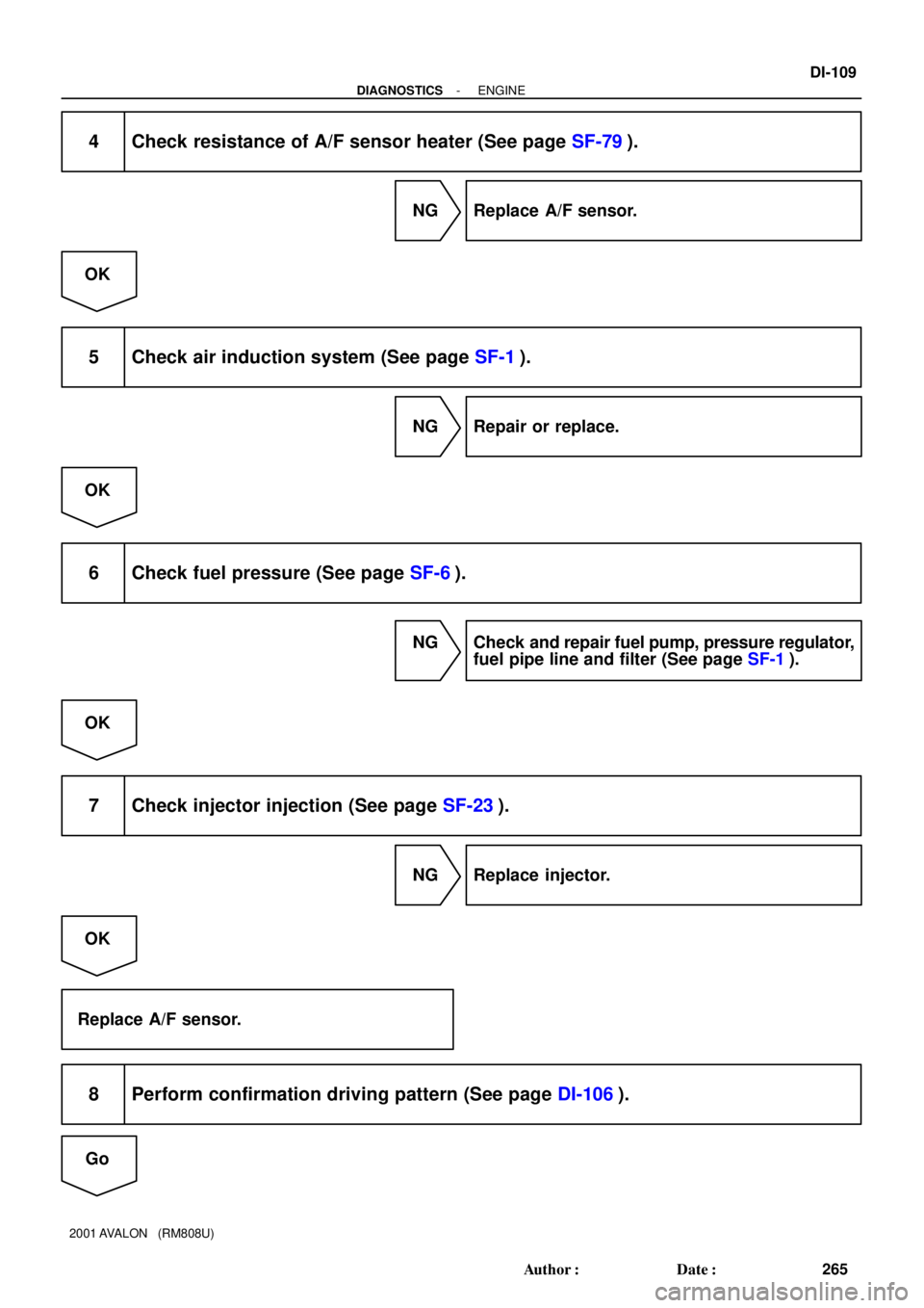
4 Check resistance of A/F sensor heater (See page SF-79).
NG Replace A/F sensor.
OK
5 Check air induction system (See page SF-1).
NG Repair or replace.
OK
6 Check fuel pressure (See page SF-6).
NG Check and repair fuel pump, pressure regulator,
fuel pipe line and filter (See page SF-1).
OK
7 Check injector injection (See page SF-23).
NG Replace injector.
OK
Replace A/F sensor.
8 Perform confirmation driving pattern (See page DI-106).
Go
Page 990 of 1897

DTC P1133 A/F Sensor Circuit Response Malfunction
(Bank 1 Sensor 1)
DTC P1153 A/F Sensor Circuit Response Malfunction
(Bank 2 Sen")
- DIAGNOSTICSENGINE
DI-1 11
267 Author�: Date�:
2001 AVALON (RM808U)
DTC P1133 A/F Sensor Circuit Response Malfunction
(Bank 1 Sensor 1)
DTC P1153 A/F Sensor Circuit Response Malfunction
(Bank 2 Sensor 1)
CIRCUIT DESCRIPTION
Refer to DTC P0125 on page DI-43.
DTC No.DTC Detecting ConditionTrouble Area
P1133
P1153
After engine is warmed up, and during vehicle driving at engine
speed 1,400 rpm or more and vehicle speed 60 km/h (38 mph)
or more, if the response characteristic of A/F sensor becomes
deteriorated (2 trip detection logic)
�Open or short in A/F sensor circuit
�A/F sensor
�Air induction system
�Fuel pressure
�Injector
�ECM
WIRING DIAGRAM
Refer to DTC P0125 on page DI-43.
INSPECTION PROCEDURE
HINT:
Read freeze frame data using TOYOTA hand-held tester or OBD II scan tool. Because freeze frame records
the engine conditions when the malfunction is detected. When troubleshooting, it is useful for determining
whether the vehicle was running or stopped, the engine was warmed up or not, the air-fuel ratio was lean
or rich, etc. at the time of the malfunction.
1 Are there any other codes (besides DTC P1133, P1153) being output?
YES Go to relevant DTC chart (See page DI-14).
NO
2 Connect OBDII scan tool or TOYOTA hand-held tester, and read value for volt-
age output of A/F sensor.
PREPARATION:
(a) Connect the OBD II scan tool or TOYOTA hand-held tester to the DLC3.
(b) Warm up the A/F sensor with the engine speed at 2,500 rpm for approx. 90 sec.
CHECK:
Read the voltage of the A/F sensor on the screen of the OBD II scan tool or TOYOTA hand-held tester when
you perform all the following conditions.
DI2H8-03
Page 991 of 1897

HINT:
The voltage of the AFR+ or AFL+ terminal of the ECM is fixed at 3.3 V and the voltage of the AFR- or AFL-
terminal is fixed")
DI-1 12
- DIAGNOSTICSENGINE
268 Author�: Date�:
2001 AVALON (RM808U)
HINT:
The voltage of the AFR+ or AFL+ terminal of the ECM is fixed at 3.3 V and the voltage of the AFR- or AFL-
terminal is fixed at 3.0 V. Therefore, it is impossible to check the A/F sensor output voltage at the terminals
(AFR+, AFL+/AFR-, AFL-) of the ECM.
OK:
ConditionA/F Sensor Voltage value
Engine idling
Engine racing�Not remains at 3.30 V (0.660 V*)
�Not remains at38V(076V*) or moreDriving at engine speed 1,500 rpm or more and vehicle
speed 40 km/h (25 mph) or more, and operate throttle valve
open and close�Not remains at 3.8 V (0.76 V*) or more
�Not remains at 2.8 V (0.56 V*) or less
*: When you use the OBD II scan tool (excluding TOYOTA hand-held tester)
HINT:
�During fuel enrichment, there is a case that the output voltage of the A/F sensor is below 2.8 V (0.56
V*), it is normal.
�During fuel cut, there is a case that the output voltage of the A/F sensor is above 3.8 V (0.76 V*), it
is normal.
�If the output voltage of the A/F sensor remains at 3.30 V (0.660 V*) even after performing all the above
conditions, the A/F sensor circuit may be open.
�If the output voltage of the A/F sensor remains at 3.8 V (0.76V*) or more, or 2.8 V (0.56 V*) or less even
after performing all the above conditions, the A/F sensor circuit may be short.
*: When you use the OBD II scan tool (excluding TOYOTA hand-held tester).
OK Go to step 9.
NG
3 Check for open and short in harness and connector between ECM and A/F sen-
sor (See page IN-30).
NG Repair or replace harness or connector.
OK
4 Check resistance of A/F sensor heater (See page SF-79).
NG Replace A/F sensor.
OK
Page 992 of 1897
- DIAGNOSTICSENGINE
DI-1 13
269 Author�: Date�:
2001 AVALON (RM808U)
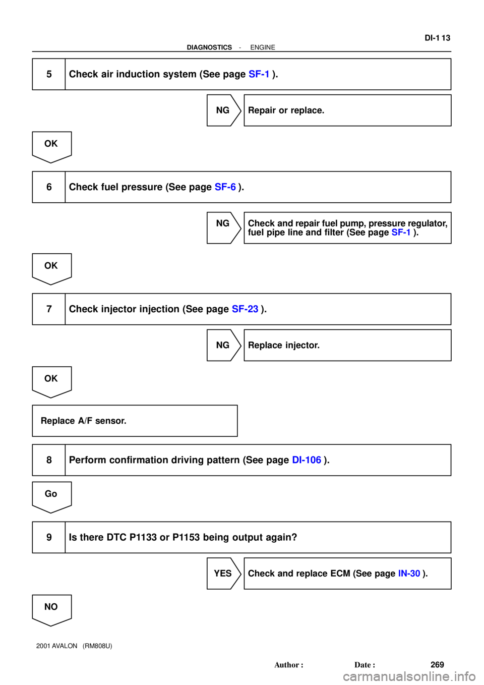
5 Check air induction system (See page SF-1).
NG Repair or replace.
OK
6 Check fuel pressure (See page SF-6).
NG Check and repair fuel pump, pressure regulator,
fuel pipe line and filter (See page SF-1).
OK
7 Check injector injection (See page SF-23).
NG Replace injector.
OK
Replace A/F sensor.
8 Perform confirmation driving pattern (See page DI-106).
Go
9 Is there DTC P1133 or P1153 being output again?
YES Check and replace ECM (See page IN-30).
NO
Page 994 of 1897

(-)
- DIAGNOSTICSENGINE
DI-1 15
271 Author�: Date�:
2001 AVALON (RM808U)
DTC P1135 A/F Sensor Heater Circuit Malfunction (Bank
1 Sensor 1)
DTC P1155 A/F Sensor Heater Circuit")
A02032
HAFL ON
HAFR
(+)
(-)
- DIAGNOSTICSENGINE
DI-1 15
271 Author�: Date�:
2001 AVALON (RM808U)
DTC P1135 A/F Sensor Heater Circuit Malfunction (Bank
1 Sensor 1)
DTC P1155 A/F Sensor Heater Circuit Malfunction (Bank
2 Sensor 1)
CIRCUIT DESCRIPTION
Refer to DTC P0125 on page DI-43.
DTC No.DTC Detecting ConditionTrouble Area
P1135
When the heater operates, heater current exceeds 8 A
(2 trip detection logic)�Open or short in heater circuit of A/F sensor
A/F h tP1135
P1155Heater current of 0.25 A or less when the heater operates
(2 trip detection logic)�A/F sensor heater
�ECM
WIRING DIAGRAM
Refer to DTC P0125 on page DI-43.
INSPECTION PROCEDURE
HINT:
Read freeze frame data using TOYOTA hand-held tester or OBD II scan tool. Because freeze frame records
the engine conditions when the malfunction is detected. When troubleshooting, it is useful for determining
whether the vehicle was running or stopped, the engine was warmed up or not, the air-fuel ratio was lean
or rich, etc. at the time of the malfunction.
1 Check voltage between terminals HAFL, HAFR of ECM connector and body
ground.
PREPARATION:
(a) Remove the glove compartment (See page SF-83).
(b) Turn the ignition switch ON.
CHECK:
Measure the voltage between terminals HAFL, HAFR of the
ECM connector and body ground.
OK:
Voltage: 9 - 14 V
OK Check and replace ECM (See page IN-30).
NG
2 Check resistance of A/F sensor heater (See page SF-79).
DI2H9-03
Page 995 of 1897
DI-1 16
- DIAGNOSTICSENGINE
272 Author�: Date�:
2001 AVALON (RM808U)
NG Replace A/F sensor.
OK
3 Check A/F sensor heater relay (Marking: A/F) (See page SF-61).
NG Replace A/F sensor heater relay.
OK
Check and repair harness or connector between A/F sensor heater relay and A/F sensor, and A/F
sensor and ECM (See page IN-30).
Page 1002 of 1897
- DIAGNOSTICSENGINE
DI-123
279 Author�: Date�:
2001 AVALON (RM808U)
DTC P1335 Crankshaft Position Sensor Circuit Malfunc-
tion (During engine running)
CIRCUIT DESCRIPTION
Refer to DTC P0335 on page DI-67.
DTC No.DTC Detecting ConditionTrouble Area
P1335No crankshaft position sensor signal to ECM with engine
speed 1,000 rpm or more
�Open or short in crankshaft position sensor circuit
�Crankshaft position sensor
�Crankshaft timing pulley
�ECM
WIRING DIAGRAM
Refer to DTC P0335 on page DI-67.
INSPECTION PROCEDURE
Refer to DTC P0335 on page DI-67.
HINT:
Read freeze frame data using TOYOTA hand-held tester or OBD II scan tool. Because freeze frame records
the engine conditions when the malfunction is detected. When troubleshooting, it is useful for determining
whether the vehicle was running or stopped, the engine was warmed up or not, the air-fuel ratio was lean
or rich, etc. at the time of the malfunction.
DI085-09
Page 1003 of 1897

VV1
NE VV2GND
GND
GND
DI-124
- DIAGNOSTICSENGINE
280 Author�: Date�:
2001 AVALON (RM808U)
DTC P1345 VVT Sensor/Camshaf")
A11663
VV1, VV2 and NE Signal Waveforms2 V
/Division
20 msec./Division (Idling)
VV1
NE VV2GND
GND
GND
DI-124
- DIAGNOSTICSENGINE
280 Author�: Date�:
2001 AVALON (RM808U)
DTC P1345 VVT Sensor/Camshaft Position Sensor Cir-
cuit Malfunction (Bank 1)
DTC P1350 VVT Sensor/Camshaft Position Sensor Cir-
cuit Malfunction (Bank 2)
CIRCUIT DESCRIPTION
VVT sensor (VV signal) consists of a magnet, iron core and pickup coil.
The VV signal plate has 3 teeth on its outer circumference and is installed the camshaft timing gear.
When the camshafts rotate, the protrusion on the signal plate and the air gap on the pickup coil change,
causing fluctuations in the magnetic field and generating an electromotive force in the pickup coil.
The actual camshaft angle is detected by the VVT sensor and it provides feedback to the ECM to control
the intake valve timing in response to during condition.
DTC No.DTC Detecting ConditionTrouble Area
No VVT sensor (Camshaft position sensor) signal to ECM
during cranking at 4 sec. or more
�Open or short in VVT sensor (camshaft position sensor) cir-
P1345
P1350No VVT sensor (Camshaft position sensor) signal to ECM with
5 sec. or more engine speed 600 rpm or morecuit
�VVT sensor (camshaft position sensor)
�Camshaft timing gearP1350
While crankshaft rotates twice, VVT sensor (Camshaft position
sensor) signal will be input to ECM 5 times.�Camshaft timing gear
�ECM
WIRING DIAGRAM
Refer to DTC P0335 on page DI-67.
INSPECTION PROCEDURE
HINT:
�If DTC P1345 is displayed, check left bank VVT sensor (camshaft position sensor).
�If DTC P1350 is displayed, check right bank VVT sensor (camshaft position sensor).
�Read freeze frame data using TOYOTA hand-held tester or OBD II scan tool. Because freeze frame
records the engine conditions when the malfunction is detected. When troubleshooting, it is useful for
determining whether the vehicle was running or stopped, the engine was warmed up or not, the air-fuel
ratio was lean or rich, etc. at the time of the malfunction.
1 Check resistance of VVT sensor (See page IG-7).
Reference: INSPECTION USING OSCILLOSCOPE
During idling, check the waveforms between terminals VV1 and
NE+, and VV2 and NE- of the ECM connector.
HINT:
�The correct waveforms are as shown.
�The waveform frequency is shortened as the engine
speed becomes higher.
NG Replace VVT sensor.
DI6T9-01