Page 936 of 1897
DI-52
- DIAGNOSTICSENGINE
208 Author�: Date�:
2001 AVALON (RM808U)
OK
Check and repair harness or connector between EFI main relay (Marking: EFI) and heated oxygen
sensor, and heated oxygen sensor and ECM (See page IN-30).
Page 937 of 1897

DTC P0300 Random/Multiple Cylinder Misfire Detected
DTC P0301 Cylinder 1 Misfire Detected
DTC P0302 Cylinder 2 Misfire Detected
DT")
DI-58
- DIAGNOSTICSENGINE
214 Author�: Date�:
2001 AVALON (RM808U)
DTC P0300 Random/Multiple Cylinder Misfire Detected
DTC P0301 Cylinder 1 Misfire Detected
DTC P0302 Cylinder 2 Misfire Detected
DTC P0303 Cylinder 3 Misfire Detected
DTC P0304 Cylinder 4 Misfire Detected
DTC P0305 Cylinder 5 Misfire Detected
DTC P0306 Cylinder 6 Misfire Detected
CIRCUIT DESCRIPTION
Misfire: The ECM uses the crankshaft position sensor and camshaft position sensor to monitor changes in
the crankshaft rotation for each cylinder.
The ECM counts the number of times the engine speed change rate indicates that misfire has occurred.
When the misfire rate equals or exceeds the count indicating that the engine condition has deteriorated, the
MIL lights up.
If the misfire rate is high enough and the driving conditions will cause catalyst overheating, the MIL blinks
when misfiring occurs.
DTC No.DTC Detecting ConditionTrouble Area
P0300Misfiring of random cylinders is detected during any particular
200 or 1,000 revolutions�Open or short in engine wire
�Connector connection
�Vacuum hose connection
P0301
P0302
P0303For any particular 200 revolutions for engine, misfiring is de-
tected which can cause catalyst overheating (This causes MIL
to blink)
�Ignition system
�Injector
�Fuel pressure
�Mass air flow meter
�Engine coolant tempsensorP0303
P0304
P0305
P0306For any particular 1,000 revolutions of engine, misfiring is de-
tected which causes a deterioration in emission (2 trip detec-
tion logic)
�Engine coolant temp. sensor
�Compression pressure
�Valve clearance
�Valve timing
�ECM
DI07S-10
Page 942 of 1897
- DIAGNOSTICSENGINE
DI-63
219 Author�: Date�:
2001 AVALON (RM808U)
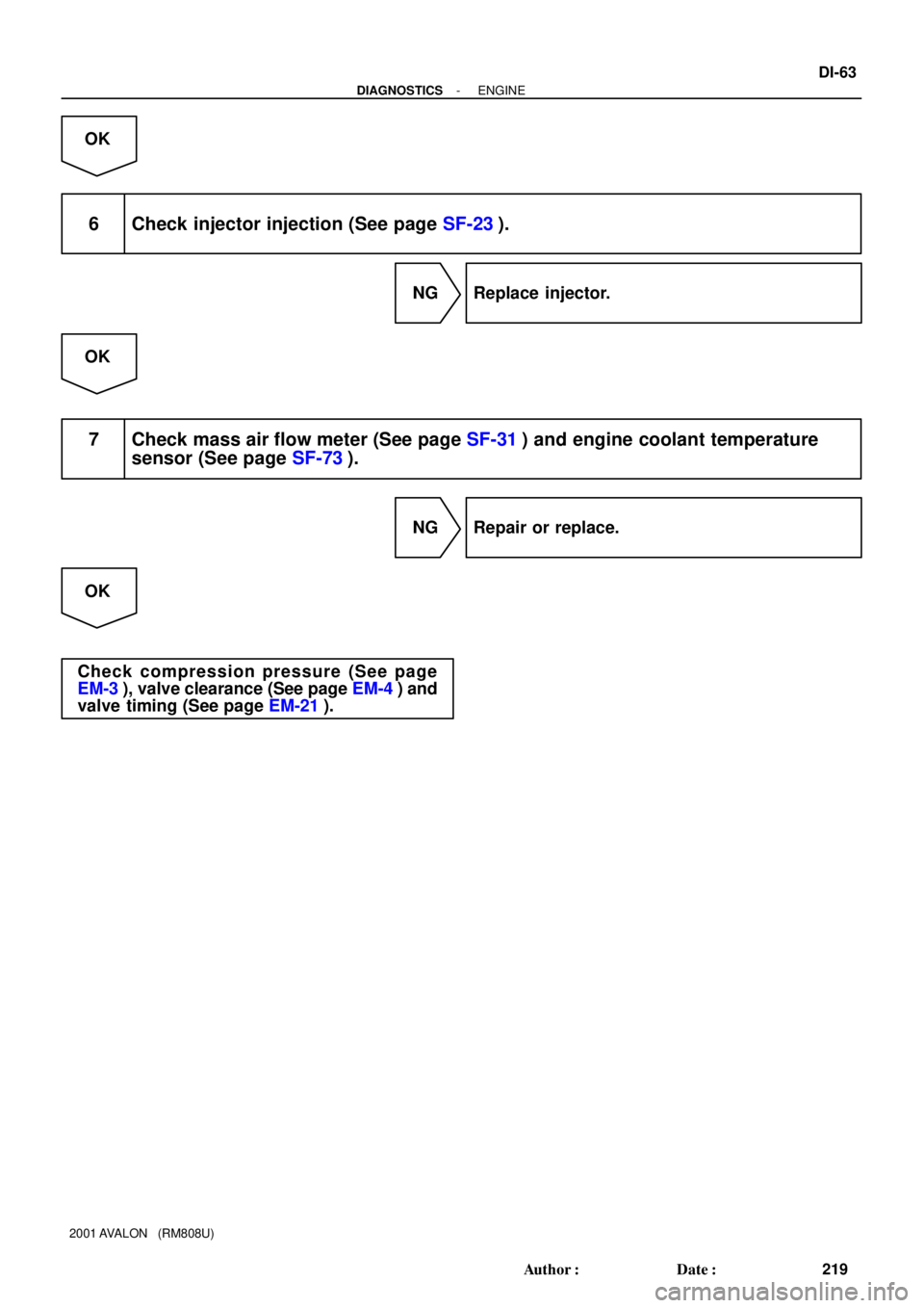
OK
6 Check injector injection (See page SF-23).
NG Replace injector.
OK
7 Check mass air flow meter (See page SF-31) and engine coolant temperature
sensor (See page SF-73).
NG Repair or replace.
OK
Check compression pressure (See page
EM-3), valve clearance (See page EM-4) and
valve timing (See page EM-21).
Page 943 of 1897

Knock Sensor 2
(on Left Bank)EB1 1
1W
W1
2W
WE4ECM
27
28KNKR
KNKLE1
E1 E4 EB1 DI-64
- DIAGNOSTICSENGINE
220 Author�: Date�:
2001 AVALON (RM808U)
DTC P0325 Knock")
A03315
Knock Sensor 1
(on Right Bank)
Knock Sensor 2
(on Left Bank)EB1 1
1W
W1
2W
WE4ECM
27
28KNKR
KNKLE1
E1 E4 EB1 DI-64
- DIAGNOSTICSENGINE
220 Author�: Date�:
2001 AVALON (RM808U)
DTC P0325 Knock Sensor 1 Circuit Malfunction (Bank 1)
DTC P0330 Knock Sensor 2 Circuit Malfunction (Bank 2)
CIRCUIT DESCRIPTION
Each of knock sensor is fitted to the right bank and left bank of the cylinder block to detect engine knocking.
This sensor contains a piezoelectric element which generates a voltage when it becomes deformed, which
occurs when the cylinder block vibrates due to knocking. If engine knocking occurs, ignition timing is retarded
to suppress it.
DTC No.DTC Detecting ConditionTrouble Area
P0325No knock sensor 1 signal to ECM with engine speed between
2,000 rpm and 5,600 rpm�Open or short in knock sensor 1 circuit
�Knock sensor 1 (looseness)
�ECM
P0330No knock sensor 1 signal to ECM with engine speed between
2,000 rpm and 5,600 rpm�Open or short in knock sensor 2 circuit
�Knock sensor 2 (looseness)
�ECM
If the ECM detects the above diagnosis conditions, it operates the fail-safe function in which the corrective
retard angle value is set to the maximum value.
WIRING DIAGRAM
INSPECTION PROCEDURE
HINT:
�DTC P0325 is for the right bank knock sensor circuit.
�DTC P0330 is for the left bank knock sensor circuit.
DI07T-09
Page 944 of 1897

A00304
Knock SensorECM
EB1
Male
ConnectorFemale
Connector 1
111
22KNKR
KNKL
EB1
E4
E427
28
FI7050
S06024
S06025
FI6510FI6607A00113
KNK Signal Waveform
0.5 V
/Division
5 msec./Division
100 msec./Division 0V
200 mV
/Division
0V
- DIAGNOSTICSENGINE
DI-65
221 Author�: Date�:
2001 AVALON (RM808U)
�Read freeze frame data using TOYOTA hand-held tester or OBD II scan tool. Because freeze frame
records the engine conditions when the malfunction is detected. When troubleshooting, it is useful for
determining whether the vehicle was running or stopped, the engine was warmed up or not, the air-fuel
ratio was lean or rich, etc. at the time of the malfunction.
1 Connect OBD II scan tool or TOYOTA hand-held tester, and check knock sensor
circuit.
PREPARATION:
(a) Connect the OBD II scan tool or TOYOTA hand-held tes-
ter to the DLC3.
(b) Disconnect the wire from wire connector EB1.
(c) Connect the terminals of the disconnected EB1 male con-
nector and EB1 female as follows.
Male connector eFemale connector
Terminal 1 e Terminal 2
Terminal 2 e Terminal 1
(d) Turn the ignition switch ON and push the OBD II scan tool
or TOYOTA hand-held tester main switch ON.
(e) After the engine is warmed up, perform quick racing to
4,000 rpm 3 times.
CHECK:
Check the DTC.
RESULT:
Type IDTC same as when vehicle brought in
P0325 " P0325 or P0330 " P0330
Type IIDTC different to when vehicle brought in
P0325 " P0330 or P0330 " P0325
Reference: INSPECTION USING OSCILLOSCOPE
�With the engine racing (4,000 rpm), check the waveform
between terminals KNKR, KNKL of the ECM connector
and body ground.
HINT:
The correct waveform is as shown.
�Spread the time on the horizontal axis, and confirm that
period of the wave is 141 msec. (Normal mode vibration
frequency of knock sensor: 7.1 kHz)
HINT:
If normal mode vibration frequency is not 7.1 kHz, the sensor
is malfunctioning.
Type II Go to step 3.
Page 945 of 1897
DI-66
- DIAGNOSTICSENGINE
222 Author�: Date�:
2001 AVALON (RM808U)
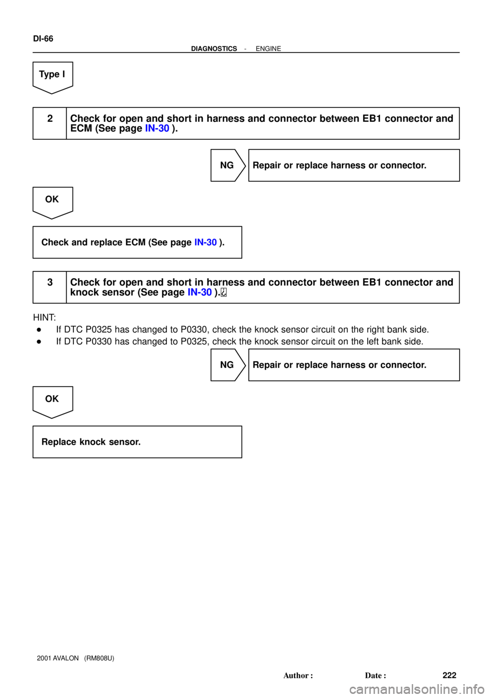
Type I
2 Check for open and short in harness and connector between EB1 connector and
ECM (See page IN-30).
NG Repair or replace harness or connector.
OK
Check and replace ECM (See page IN-30).
3 Check for open and short in harness and connector between EB1 connector and
knock sensor (See page IN-30).
HINT:
�If DTC P0325 has changed to P0330, check the knock sensor circuit on the right bank side.
�If DTC P0330 has changed to P0325, check the knock sensor circuit on the left bank side.
NG Repair or replace harness or connector.
OK
Replace knock sensor.
Page 946 of 1897

Crankshaft Position Sensor1
2
1
2
B-W B-W
L
L16
2410ECM
VV1+
NE+
NE-
E2
21LB-W
LE4
E5
VV2+ 22 Left Bank VVT Sensor (Camshaft Position Sensor)E5")
A11084
Right Bank VVT Sensor (Camshaft Position Sensor)
Crankshaft Position Sensor1
2
1
2
B-W B-W
L
L16
2410ECM
VV1+
NE+
NE-
E2
21LB-W
LE4
E5
VV2+ 22 Left Bank VVT Sensor (Camshaft Position Sensor)E5
E4 CC
C
CJ8 J/C
- DIAGNOSTICSENGINE
DI-67
223 Author�: Date�:
2001 AVALON (RM808U)
DTC P0335 Crankshaft Position Sensor ºAº Circuit Mal-
function
CIRCUIT DESCRIPTION
Crankshaft position sensor (NE signal) consists of a magnet, iron core and pickup coil.
The NE signal plate has 34 teeth and is installed the crankshaft timing pulley. The NE signal sensor gener-
ates 34 signals at every engine revolution. The ECM detects the standard crankshaft angle based on the
G (VV) signal, and the actual crankshaft angle and the engine speed by the NE signal.
DTC No.DTC Detecting ConditionTrouble Area
P0335
No crankshaft position sensor signal to ECM during cranking
(2 trip detection logic)�Open or short in crankshaft position sensor circuit
�Crankshaft position sensor
P0335No crankshaft position sensor signal to ECM with engine
speed 600 rpm or more (2 trip detection logic)
�Crankshaft osition sensor
�Crankshaft timing pulley
�ECM
WIRING DIAGRAM
INSPECTION PROCEDURE
HINT:
�Perform troubleshooting of DTC P0335 first. If no trouble is found, troubleshoot the following mechani-
cal systems.
�Read freeze frame data using TOYOTA hand-held tester or OBD II scan tool. Because freeze frame
records the engine conditions when the malfunction is detected. When troubleshooting, it is useful for
determining whether the vehicle was running or stopped, the engine was warmed up or not, the air-fuel
ratio was lean or rich, etc. at the time of the malfunction.
DI07U-09
Page 947 of 1897
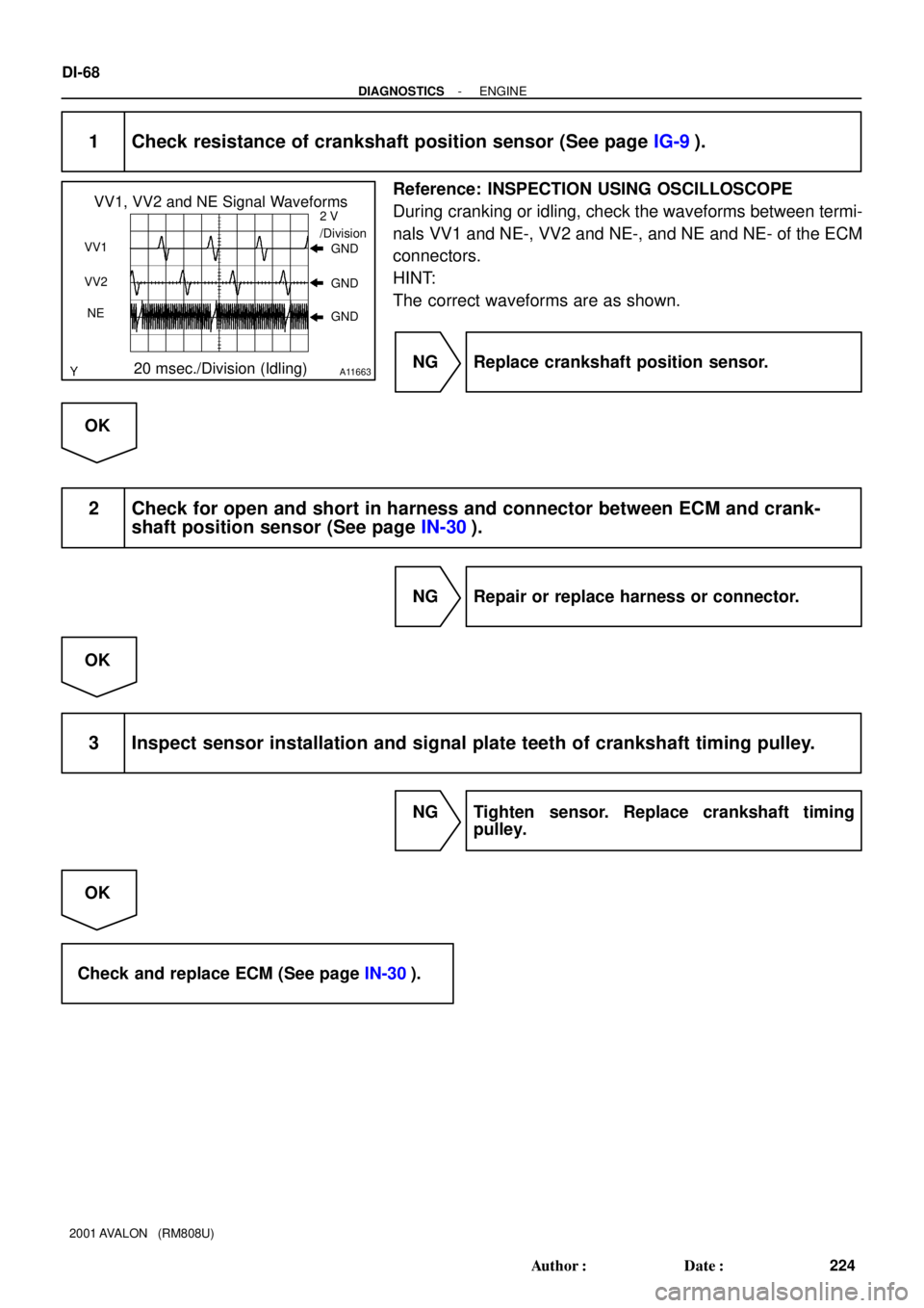
A11663
VV1, VV2 and NE Signal Waveforms2 V
/Division
20 msec./Division (Idling)
VV1
NE VV2GND
GND
GND
DI-68
- DIAGNOSTICSENGINE
224 Author�: Date�:
2001 AVALON (RM808U)
1 Check resistance of crankshaft position sensor (See page IG-9).
Reference: INSPECTION USING OSCILLOSCOPE
During cranking or idling, check the waveforms between termi-
nals VV1 and NE-, VV2 and NE-, and NE and NE- of the ECM
connectors.
HINT:
The correct waveforms are as shown.
NG Replace crankshaft position sensor.
OK
2 Check for open and short in harness and connector between ECM and crank-
shaft position sensor (See page IN-30).
NG Repair or replace harness or connector.
OK
3 Inspect sensor installation and signal plate teeth of crankshaft timing pulley.
NG Tighten sensor. Replace crankshaft timing
pulley.
OK
Check and replace ECM (See page IN-30).