Page 1884 of 1897
SA0WD-02
W03647
- SUSPENSION AND AXLEREAR SHOCK ABSORBER
SA-53
1387 Author�: Date�:
2001 AVALON (RM808U)
DISPOSAL
1. FULLY EXTEND SHOCK ABSORBER ROD
2. DRILL HOLE TO DISCHARGE GAS FROM CYLINDER
Using a drill, make a hole in the cylinder as shown in the illustra-
tion to discharge the gas inside.
CAUTION:
�When drilling, chips may fly out, work carefully.
�The gas is colorless, odorless and non-poisonous.
Page 1885 of 1897
SA0WC-02
W03646
SA-52
- SUSPENSION AND AXLEREAR SHOCK ABSORBER
1386 Author�: Date�:
2001 AVALON (RM808U)
INSPECTION
INSPECT SHOCK ABSORBER
Compress and extend the shock absorber rod and check that
there is no abnormal resistance or unusual sound during opera-
tion.
If there is any abnormality, replace the shock absorber with a
new one.
NOTICE:
When disposing of the shock absorber, see DISPOSAL on
page SA-53.
Page 1886 of 1897
SA0WF-02
- SUSPENSION AND AXLEREAR SHOCK ABSORBER
SA-55
1389 Author�: Date�:
2001 AVALON (RM808U)
INSTALLATION
Installation is in the reverse order of removal (See page SA-50).
HINT:
After installation, check the rear wheel alignment (See page SA-7).
Page 1887 of 1897
SA0WE-02
R00911
SST
R00912
F06469
Outside Suspension Support
Lower Bracket
SA-54
- SUSPENSION AND AXLEREAR SHOCK ABSORBER
1388 Author�: Date�:
2001 AVALON (RM808U)
REASSEMBLY
1. INSTALL LOWER INSULATOR
2. INSTALL SPRING BUMPER TO PISTON ROD
3. INSTALL COIL SPRING
(a) Using SST, compress the coil spring.
SST 09727-30021
NOTICE:
Do not use an impact wrench. It will damage the SST.
(b) Install the coil spring to the shock absorber.
HINT:
Fit the lower end of the coil spring into the gap of the lower insu-
lator.
4. INSTALL SUSPENSION SUPPORT
(a) Install the suspension support to the piston rod.
(b) Install the collar.
(c) Temporarily tighten a new nut.
(d) Rotate the suspension support to set it in the correct
direction shown in the illustration.
(e) Remove the SST.
SST 09727-30021
HINT:
After removing SST, recheck the direction of the suspension
support.
Page 1888 of 1897

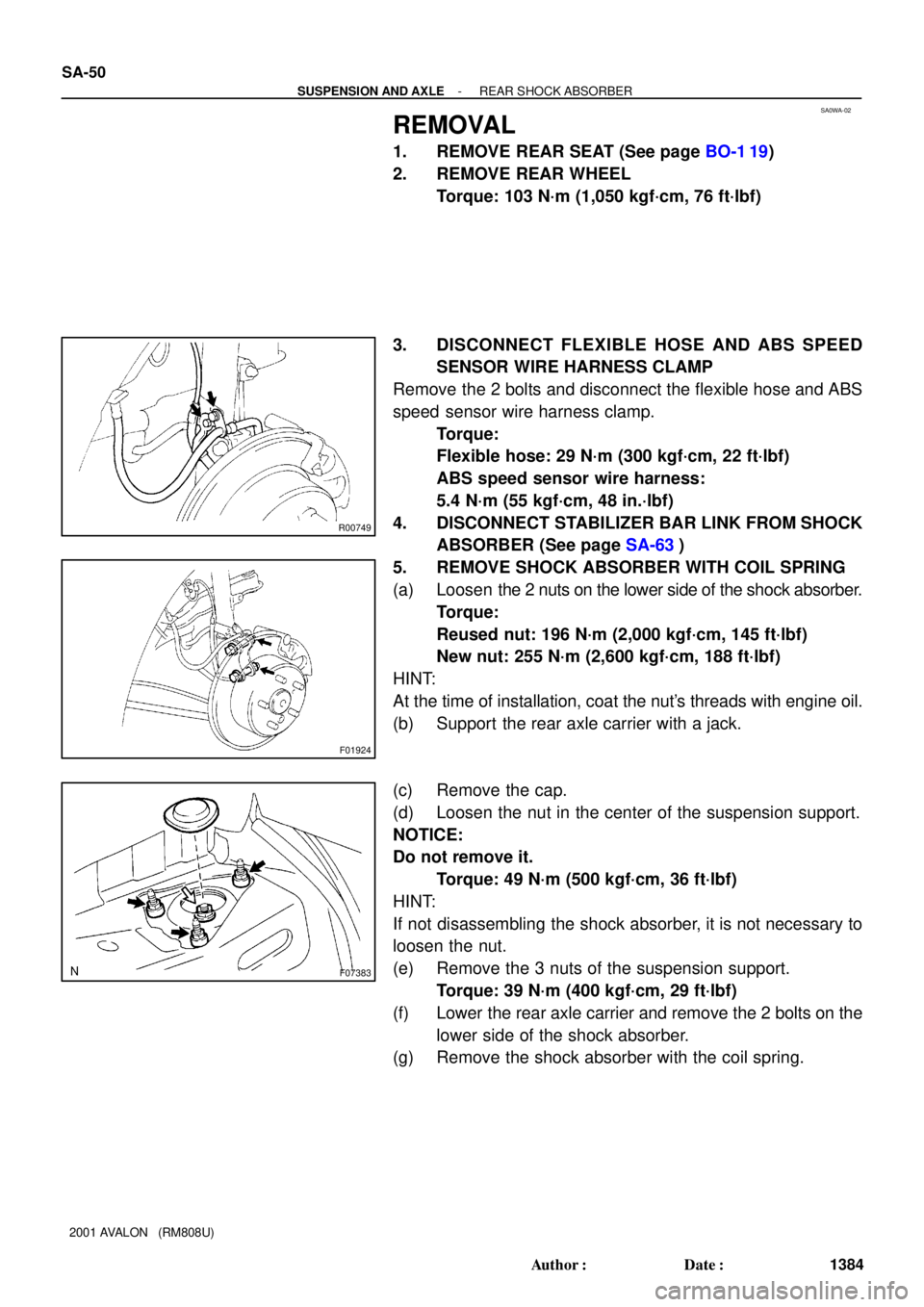
SA0WA-02
R00749
F01924
F07383
SA-50
- SUSPENSION AND AXLEREAR SHOCK ABSORBER
1384 Author�: Date�:
2001 AVALON (RM808U)
REMOVAL
1. REMOVE REAR SEAT (See page BO-1 19)
2. REMOVE REAR WHEEL
Torque: 103 N´m (1,050 kgf´cm, 76 ft´lbf)
3. DISCONNECT FLEXIBLE HOSE AND ABS SPEED
SENSOR WIRE HARNESS CLAMP
Remove the 2 bolts and disconnect the flexible hose and ABS
speed sensor wire harness clamp.
Torque:
Flexible hose: 29 N´m (300 kgf´cm, 22 ft´lbf)
ABS speed sensor wire harness:
5.4 N´m (55 kgf´cm, 48 in.´lbf)
4. DISCONNECT STABILIZER BAR LINK FROM SHOCK
ABSORBER (See page SA-63)
5. REMOVE SHOCK ABSORBER WITH COIL SPRING
(a) Loosen the 2 nuts on the lower side of the shock absorber.
Torque:
Reused nut: 196 N´m (2,000 kgf´cm, 145 ft´lbf)
New nut: 255 N´m (2,600 kgf´cm, 188 ft´lbf)
HINT:
At the time of installation, coat the nut's threads with engine oil.
(b) Support the rear axle carrier with a jack.
(c) Remove the cap.
(d) Loosen the nut in the center of the suspension support.
NOTICE:
Do not remove it.
Torque: 49 N´m (500 kgf´cm, 36 ft´lbf)
HINT:
If not disassembling the shock absorber, it is not necessary to
loosen the nut.
(e) Remove the 3 nuts of the suspension support.
Torque: 39 N´m (400 kgf´cm, 29 ft´lbf)
(f) Lower the rear axle carrier and remove the 2 bolts on the
lower side of the shock absorber.
(g) Remove the shock absorber with the coil spring.
Page 1889 of 1897
SA0VK-02
F07397N´m (kgf´cm, ft´lbf) : Specified torque
Bushing
Stabilizer Bar Bracket Stabilizer Bar
Stabilizer Bar Link
19 (195, 14)19 (195, 14)
39 (400, 29)
39 (400, 29)
SA-62
- SUSPENSION AND AXLEREAR STABILIZER BAR
1396 Author�: Date�:
2001 AVALON (RM808U)
REAR STABILIZER BAR
COMPONENTS
Page 1890 of 1897
SA0VM-01
Z00340
SA-64
- SUSPENSION AND AXLEREAR STABILIZER BAR
1398 Author�: Date�:
2001 AVALON (RM808U)
INSPECTION
INSPECT STABILIZER BAR LINK BALL JOINT FOR ROTA-
TION CONDITION
(a) As shown in the illustration, flip the ball joint stud back and
forth 5 times, before installing the nut.
(b) Using a torque wrench, turn the nut continuously at a rate
of 2 - 4 seconds per 1 turn and take the torque reading
on the 5th turn.
Turning torque:
0.05 - 1.0 N´m (0.5 - 10 kgf´cm, 0.4 - 8.7 in.´lbf)
Page 1891 of 1897
SA0VN-01
- SUSPENSION AND AXLEREAR STABILIZER BAR
SA-65
1399 Author�: Date�:
2001 AVALON (RM808U)
INSTALLATION
Installation is in the reverse order of removal (See page SA-63).