Page 1860 of 1897
SA0V2-02
W03646
SA-28
- SUSPENSION AND AXLEFRONT SHOCK ABSORBER
1362 Author�: Date�:
2001 AVALON (RM808U)
INSPECTION
INSPECT SHOCK ABSORBER
Compress and extend the shock absorber rod and check that
there is no abnormal resistance or unusual sound during opera-
tion.
If there is any abnormality, replace the shock absorber with a
new one.
NOTICE:
When disposing of the shock absorber, see DISPOSAL on
page SA-29.
Page 1861 of 1897
SA0V5-03
- SUSPENSION AND AXLEFRONT SHOCK ABSORBER
SA-31
1365 Author�: Date�:
2001 AVALON (RM808U)
INSTALLATION
Installation is in the reverse order of removal (See page SA-26).
HINT:
After installation, check the front wheel alignment (See page SA-4).
NOTICE:
w/ VSC:
After installation, perform the steering angle sensor zero point calibration (See page DI-252).
Page 1862 of 1897

SA0V4-02
W03200
SST
W03201
W03199
SST SA-30
- SUSPENSION AND AXLEFRONT SHOCK ABSORBER
1364 Author�: Date�:
2001 AVALON (RM808U)
REASSEMBLY
1. INSTALL LOWER INSULATOR ONTO SHOCK AB-
SORBER
2. INSTALL SPRING BUMPER TO PISTON ROD
3. INSTALL COIL SPRING
(a) Using 2 SST of the same type, compress the coil spring.
SST 09727-30021
NOTICE:
Do not use an impact wrench. It will damage the SST.
(b) Install the coil spring to the shock absorber.
HINT:
Fit the lower end of the coil spring into the gap of the spring low-
er seat.
4. INSTALL SPRING UPPER SEAT AND INSULATOR
(a) Align the 'OUT' mark of spring upper seat with the mark
of the upper insulator.
(b) Install the spring upper seat with upper insulator to the
shock absorber with the mark facing to the outside of the
vehicle.
(c) Install the bearing and suspension support.
(d) Using SST to hold the suspension support, install a new
nut.
SST 09729-22031
Torque: 49 N´m (500 kgf´cm, 36 ft´lbf)
(e) Remove the 2 SST from the coil spring.
NOTICE:
Check that the bearing fits into the recess in the suspen-
sion support.
Page 1863 of 1897

SA0V0-02
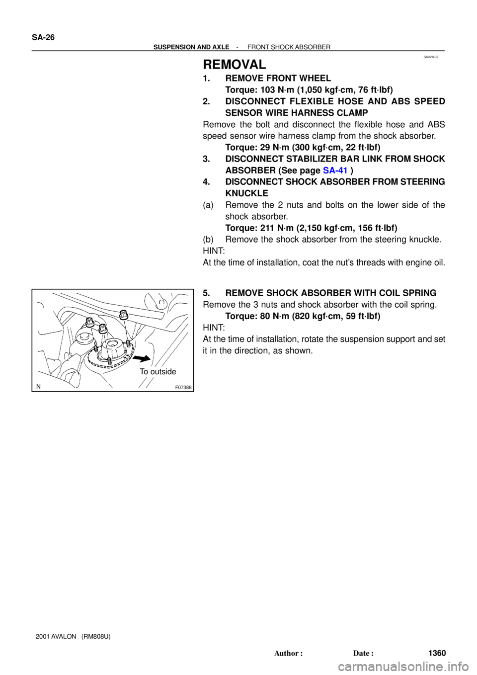
F07388
To outside SA-26
- SUSPENSION AND AXLEFRONT SHOCK ABSORBER
1360 Author�: Date�:
2001 AVALON (RM808U)
REMOVAL
1. REMOVE FRONT WHEEL
Torque: 103 N´m (1,050 kgf´cm, 76 ft´lbf)
2. DISCONNECT FLEXIBLE HOSE AND ABS SPEED
SENSOR WIRE HARNESS CLAMP
Remove the bolt and disconnect the flexible hose and ABS
speed sensor wire harness clamp from the shock absorber.
Torque: 29 N´m (300 kgf´cm, 22 ft´lbf)
3. DISCONNECT STABILIZER BAR LINK FROM SHOCK
ABSORBER (See page SA-41)
4. DISCONNECT SHOCK ABSORBER FROM STEERING
KNUCKLE
(a) Remove the 2 nuts and bolts on the lower side of the
shock absorber.
Torque: 211 N´m (2,150 kgf´cm, 156 ft´lbf)
(b) Remove the shock absorber from the steering knuckle.
HINT:
At the time of installation, coat the nut's threads with engine oil.
5. REMOVE SHOCK ABSORBER WITH COIL SPRING
Remove the 3 nuts and shock absorber with the coil spring.
Torque: 80 N´m (820 kgf´cm, 59 ft´lbf)
HINT:
At the time of installation, rotate the suspension support and set
it in the direction, as shown.
Page 1864 of 1897
SA0W2-02
F06453N´m (kgf´cm, ft´lbf) : Specified torque
39 (400, 29)19 (195, 14)
Bracket
Bushing Stabilizer
Bar Link
39 (400, 29)
Stabilizer Bar
39 (400, 29)
39 (400, 29)
BushingBracket
Stabilizer Bar Link
19 (195, 14)
SA-40
- SUSPENSION AND AXLEFRONT STABILIZER BAR
1374 Author�: Date�:
2001 AVALON (RM808U)
FRONT STABILIZER BAR
COMPONENTS
Page 1865 of 1897
SA0W4-01
Z00340
SA-42
- SUSPENSION AND AXLEFRONT STABILIZER BAR
1376 Author�: Date�:
2001 AVALON (RM808U)
INSPECTION
INSPECT STABILIZER BAR LINK BALL JOINT FOR ROTA-
TION CONDITION
(a) As shown in the illustration, flip the ball joint stud back and
forth 5 times, before installing the nut.
(b) Using a torque wrench, turn the nut continuously at a rate
of 2 - 4 seconds per 1 turn and take the torque reading
on the 5th turn.
Turning torque:
0.05 - 1.0 N´m (0.5 - 10 kgf´cm, 0.4 - 8.7 in.´lbf)
Page 1866 of 1897
SA0W5-01
- SUSPENSION AND AXLEFRONT STABILIZER BAR
SA-43
1377 Author�: Date�:
2001 AVALON (RM808U)
INSTALLATION
Installation is in the reverse order of removal (See page SA-41).
Page 1867 of 1897
SA0W3-02
F06454
F06456
- SUSPENSION AND AXLEFRONT STABILIZER BAR
SA-41
1375 Author�: Date�:
2001 AVALON (RM808U)
REMOVAL
1. REMOVE FRONT WHEELS
Torque: 103 N´m (1,050 kgf´cm, 76 ft´lbf)
2. REMOVE STABILIZER BAR LINKS
(a) Remove the 2 nuts and stabilizer bar link.
Torque: 39 N´m (400 kgf´cm, 29 ft´lbf)
HINT:
If the ball joint turns together with the nut, use a hexagon (5 mm)
wrench to hold the stud.
(b) Employ the same manner described above to the other
side.
3. REMOVE BRACKETS AND BUSHINGS
(a) Remove the 2 bolts, bracket and bushing.
Torque: 19 N´m (195 kgf´cm, 14 ft´lbf)
HINT:
At the time of installation, install the bushing to the inside of the
bushing stopper on the stabilizer bar.
(b) Employ the same manner described above to the other
side.
4. REMOVE STABILIZER BAR
Remove the stabilizer bar from the left hand side.
NOTICE:
Be careful not to damage the pressure feed tube.