Page 832 of 1897
I13655
W-B88
4F 4E
W-B1
2 D8
Wireless Door
Control Receiver
L-WL-W 9
IK221Body ECU
B4 RDA RDA
E
PRG
+B
P-L1
1
4D
4E
P-L5320
G-R G-R7
B4 PRG
B
BJ6
J/C
II7
1D
FL
MAIN DOME
9
1J
W-L
2
2G 2C1
B
1
1
F7 F6
BBattery J/B No. 4
J/B No. 4
IK2
Driver Side J/B
DCC Engine Room J/B
FL Block W-B
- DIAGNOSTICSBODY CONTROL SYSTEM
DI-651
807 Author�: Date�:
2001 AVALON (RM808U)
Wireless door lock tuner circuit
CIRCUIT DESCRIPTION
The signal from the transmitter will be input to the body ECU through RDA line. RDA line is diagnosed by
the Body ECU, so check DTC also in case of the failure of the wireless function.
WIRING DIAGRAM
DI6LV-01
Page 846 of 1897
DI08M-14
Duty Ratio =A + BA
x 100 (%)
ON
OFFA
B
1 cycle
I13618
Cruise Control ECU
MC MO
R-B Cruise Control Actuator
R 1
215
C4
C15
MO
MCP
P II1 15
II1 14
7
- DIAGNOSTICSCRUISE CONTROL SYSTEM
DI-561
717 Author�: Date�:
2001 AVALON (RM808U)
CIRCUIT INSPECTION
DTC 11, 15 Actuator Motor Circuit
CIRCUIT DESCRIPTION
The actuator motor is operated by signals from the ECU. Acceleration and deceleration signals are trans-
mitted according to changes in the Duty Ratio (See below).
Duty Ratio
The duty ratio is the ratio of the period of continuity in one cycle. For example, if A is the period of continuity
in one cycle, and B is the period of non-continuity.
DTC No.Detection ItemTrouble Area
11Short in actuator motor circuit.
�Actuator motor
�Harness or connector between cruise control ECU and
actuator motor
�Cruise control ECU
15Open in actuator motor circuit.�Actuator motor
WIRING DIAGRAM
Page 848 of 1897

I13617
Cruise Control ECU
4 3
3
W-B8 Stop Light Switch
4Cruise Control Actuator
13
II1
IJJ9
J/CL
9P-B P-B G-B GNDL
AC4
S4
C15
W-B II1
- DIAGNOSTICSCRUISE CONTROL SYSTEM
DI-563
719 Author�: Date�:
2001 AVALON (RM808U)
DTC 12 Actuator Magnetic Clutch Circuit
CIRCUIT DESCRIPTION
This circuit turns on the magnetic clutch inside the actuator during cruise control operation according to the
signal from the ECU. If a malfunction occurs in the actuator or speed sensor, etc. during cruise control opera-
tion, the rotor shaft between the motor and control plate is released.
When the brake pedal is depressed, the stop light switch turns on, supplying electrical power to the stop light.
Power supply to the magnetic clutch is mechanically cut and the magnetic clutch is turned OFF.
When driving downhill, if the vehicle speed exceeds the set speed by 15 km/h (9 mph), the ECU turns the
safety magnet clutch OFF. If the vehicle speed later drops to within 10 km/h (6 mph), cruise control at the
set speed is resumed.
DTC No.Detection ItemTrouble Area
12Short in actuator magnetic clutch circuit.
Open (0.8 sec.) in actuator magnetic clutch circuit.
�STOP Fuse
�Stop light switch
�Actuator magnetic clutch
�Harness or connector between cruise control ECU and
actuator magnetic clutch, actuator magnetic clutch and body
ground
�Cruise control ECU
WIRING DIAGRAM
DI08N-15
Page 851 of 1897
I00055
4
3(+)
(-)
DI-566
- DIAGNOSTICSCRUISE CONTROL SYSTEM
722 Author�: Date�:
2001 AVALON (RM808U)
DTC 14 Actuator Mechanical Malfunction
CIRCUIT DESCRIPTION
The circuit detects the rotation position of the actuator control plate and sends a signal to the ECU.
DTC No.Detection ItemTrouble Area
14Cruise control actuator mechanical malfunction.
�Actuator lock: (motor, arm)
�Actuator motor
�Cruise control ECU
WIRING DIAGRAM
See page DI-563.
INSPECTION PROCEDURE
1 Check cruise control actuator arm locking operation
PREPARATION:
(a) Turn ignition switch OFF.
(b) Disconnect the actuator connector.
CHECK:
(a) Connect the positive (+) lead from the battery to the termi-
nal 3 of actuator and the negative (-) lead to terminal 4.
NOTICE:
Do not connect the high tension cables to the wrong bat-
tery terminal. The cruise control actuator will be damaged.
(b) Move the control plate by hand.
OK:
Control plate doesn't move.
NG Replace cruise control actuator.
OK
DI08O-14
Page 853 of 1897

I00292
Vehicle Speed Sensor
ECUCombination Meter
Cruise Control ECU
4 pulses/
1 rotation
of rotor shaft4 pulses/
1 rotation
of rotor shaft
I13616
Cruise Control ECU
12 Combination Meter
3C10
V-W V-W
Y-R BR
to
ABS ECU3F1
M322
M3 M37
BR IJ1 11
EBM3
to ECU-IG Fuse 18
SPD
C15
J/B No. 3
1 DI-568
- DIAGNOSTICSCRUISE CONTROL SYSTEM
724 Author�: Date�:
2001 AVALON (RM808U)
DTC 21 Open in Vehicle Speed Sensor Circuit
CIRCUIT DESCRIPTION
The signal from the vehicle speed sensor circuit is sent to cruise control ECU as vehicle speed signal.
The rotor shaft is driven by the gear of the transmission.
For each rotation of the shaft, the vehicle speed sensor sends a 4-pulse signal through the combination
meter to the cruise control ECU (See the following installation).
This signal is converted inside the combination meter and sent as a 4-pulse signal to the cruise control ECU.
The ECU calculates the vehicle speed from this pulse frequency.
DTC No.Detection ItemTrouble Area
21Speed signal is not input to the cruise control ECU while cruise
control is set.
�Combination meter
�Harness or connector between cruise control ECU and com-
bination meter, combination meter and vehicle speed sensor
�Vehicle speed sensor
�Cruise control ECU
WIRING DIAGRAM
DI08P-18
Page 856 of 1897
- DIAGNOSTICSCRUISE CONTROL SYSTEM
DI-571
727 Author�: Date�:
2001 AVALON (RM808U)
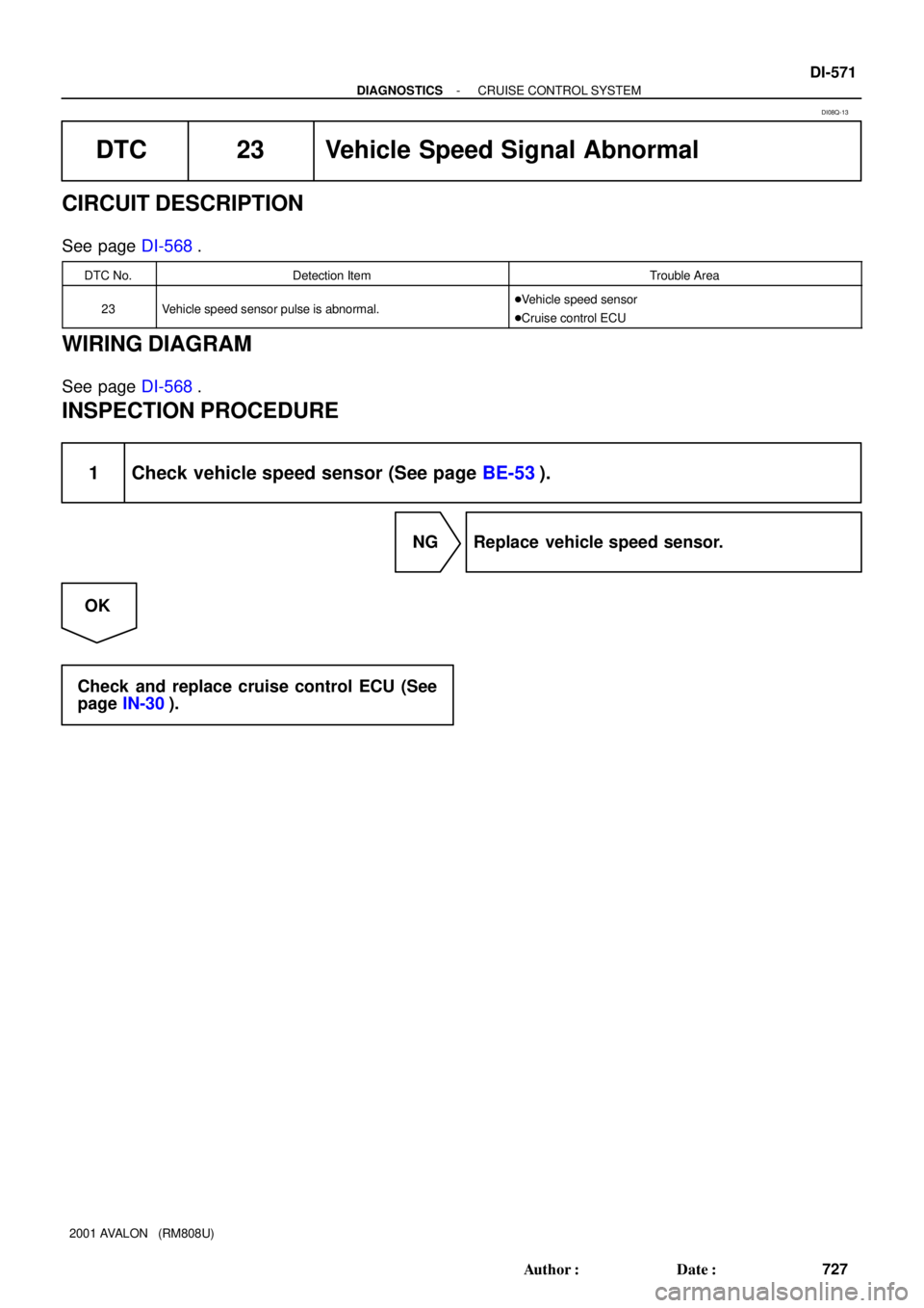
DTC 23 Vehicle Speed Signal Abnormal
CIRCUIT DESCRIPTION
See page DI-568.
DTC No.Detection ItemTrouble Area
23Vehicle speed sensor pulse is abnormal.�Vehicle speed sensor
�Cruise control ECU
WIRING DIAGRAM
See page DI-568.
INSPECTION PROCEDURE
1 Check vehicle speed sensor (See page BE-53).
NG Replace vehicle speed sensor.
OK
Check and replace cruise control ECU (See
page IN-30).
DI08Q-13
Page 857 of 1897
I13615
Cruise Control ECU
W-L
W-BW-B
MAINCANCEL
COAST/
SETRES/
ACC 41
10 3A
53
W
IG
J5
J/C 20
73A
A
A
W-BCAN
CCS Cruise Control Switch
C12
C15
J/B
No. 3 DI-572
- DIAGNOSTICSCRUISE CONTROL SYSTEM
728 Author�: Date�:
2001 AVALON (RM808U)
DTC 32 Control Switch Circuit (Cruise Control
Switch)
CIRCUIT DESCRIPTION
This circuit carries the SET/COAST, RESUME/ACCEL and CANCEL signals (each voltage) to the ECU.
DTC No.Detection ItemTrouble Area
32Short in control switch circuit.
�Cruise control switch
�Harness or connector between cruise control ECU and
cruise control switch, cruise control switch and body ground
�Cruise control ECU
WIRING DIAGRAM
DI08R-16
Page 860 of 1897
I13614
IDL 13
IDLOE725 ECMCruise Control ECU
Y
C15
- DIAGNOSTICSCRUISE CONTROL SYSTEM
DI-575
731 Author�: Date�:
2001 AVALON (RM808U)
DTC 51 Idle Signal Circuit
CIRCUIT DESCRIPTION
When the idle switch is turned ON, a signal is sent to the ECU. The ECU uses this signal to correct the dis-
crepancy between the throttle valve position and the actuator position sensor value to enable accurate
cruise control at the set speed. If the idle switch is malfunctioning, problem symptoms also occur in the en-
gine, so also inspect the engine.
DTC No.Detection ItemTrouble Area
51Short in idle signal circuit.
�Harness or connector between ECM and throttle position
sensor
�Throttle position sensor
�Harness or connector between cruise control ECU and ECM
�Cruise control ECU
WIRING DIAGRAM
DI6L6-01


ON
OFFA
B
1 cycle
I13618
Cruise Control ECU
MC MO
R-B Cruise Control Actuator
R 1
215
C4
C15
MO
MCP
P II1 15
II1 14
7
- DIAGNOSTICSCRUISE CONTROL SYSTEM
DI-561
71")