2001 NISSAN X-TRAIL check engine
[x] Cancel search: check enginePage 2749 of 3833
BRAKE FLUID
BR-9
C
D
E
G
H
I
J
K
L
MA
B
BR
BRAKE FLUIDPFP:KN100
Checking Brake Fluid Level EFS000C5
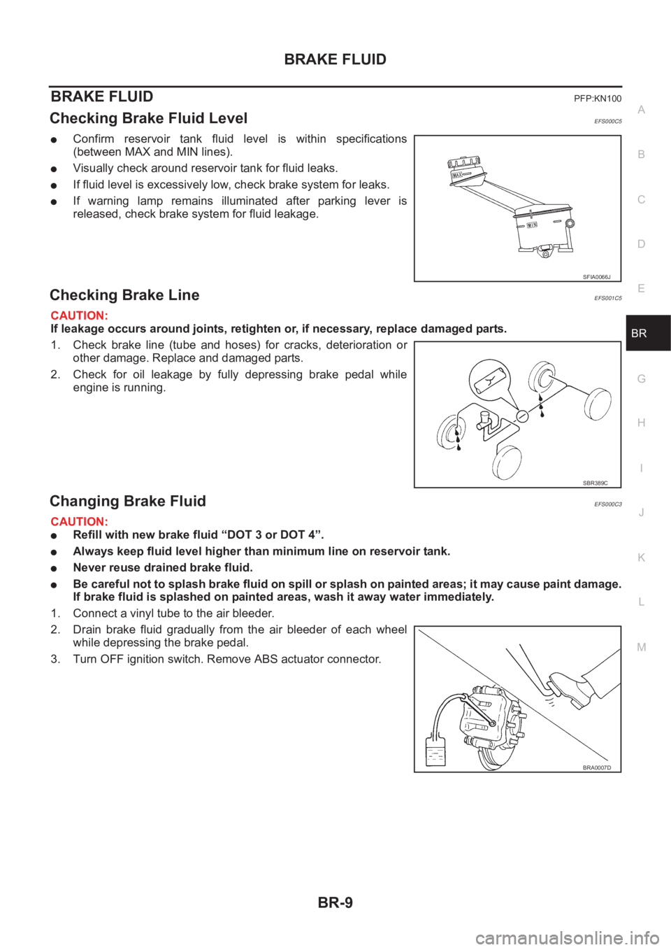
●Confirm reservoir tank fluid level is within specifications
(between MAX and MIN lines).
●Visually check around reservoir tank for fluid leaks.
●If fluid level is excessively low, check brake system for leaks.
●If warning lamp remains illuminated after parking lever is
released, check brake system for fluid leakage.
Checking Brake LineEFS001C5
CAUTION:
If leakage occurs around joints, retighten or, if necessary, replace damaged parts.
1. Check brake line (tube and hoses) for cracks, deterioration or
other damage. Replace and damaged parts.
2. Check for oil leakage by fully depressing brake pedal while
engine is running.
Changing Brake FluidEFS000C3
CAUTION:
●Refill with new brake fluid “DOT 3 or DOT 4”.
●Always keep fluid level higher than minimum line on reservoir tank.
●Never reuse drained brake fluid.
●Be careful not to splash brake fluid on spill or splash on painted areas; it may cause paint damage.
If brake fluid is splashed on painted areas, wash it away water immediately.
1. Connect a vinyl tube to the air bleeder.
2. Drain brake fluid gradually from the air bleeder of each wheel
while depressing the brake pedal.
3. Turn OFF ignition switch. Remove ABS actuator connector.
SFIA0066J
SBR389C
BRA0007D
Page 2752 of 3833
BR-12
BRAKE PIPING AND HOSE
5. Refill brake fluid until new brake fluid comes out of each air bleeder.
6. Afterwards, bleed air.
Removal and Installation of Rear Brake Piping and Brake HoseEFS000C8
REMOVAL
CAUTION:
●Do not allow brake fluid to spill or splash on painted surfaces. Brake fluid can seriously damage
paint. If it gets on a painted surface, wipe it off immediately and wash with water.
●Do not bend or twist the brake hose sharply, or strongly pull it.
●Cover brake fluid line connections to prevent dust and other foreign material from entering.
1. Connect a vinyl tube to the air bleeder.
2. Drain brake fluid gradually from the air bleeder of each wheel while depressing the brake pedal.
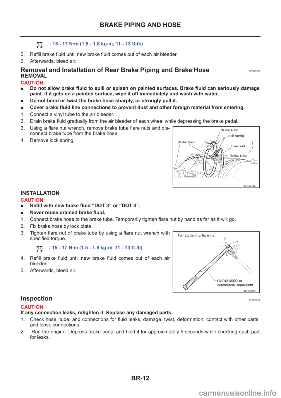
3. Using a flare nut wrench, remove brake tube flare nuts and dis-
connect brake tube from the brake hose.
4. Remove lock spring.
INSTALLATION
CAUTION:
●Refill with new brake fluid “DOT 3” or “DOT 4”.
●Never reuse drained brake fluid.
1. Connect brake hose to the brake tube. Temporarily tighten flare nut by hand as far as it will go.
2. Fix brake hose by lock plate.
3. Tighten flare nut of brake tube by using a flare nut wrench with
specified torque.
4. Refill brake fluid until new brake fluid comes out of each air
bleeder.
5. Afterwards, bleed air.
InspectionEFS000C9
CAUTION:
If any connection leaks, retighten it. Replace any damaged parts.
1. Check hose, tube, and connections for fluid leaks, damage, twist, deformation, contact with other parts,
and loose connections.
2. Run the engine. Depress brake pedal and hold it for approximately 5 seconds while checking each part
for leaks.: 15 - 17 N·m (1.5 - 1.8 kg-m, 11 - 13 ft-lb)
SFIA0046E
: 15 - 17 N·m (1.5 - 1.8 kg-m, 11 - 13 ft-lb)
SBR820BA
Page 2757 of 3833
BRAKE BOOSTER
BR-17
C
D
E
G
H
I
J
K
L
MA
B
BR
BRAKE BOOSTERPFP:47200
On-Vehicle Inspection and ServiceEFS000CC
FUNCTION INSPECTION
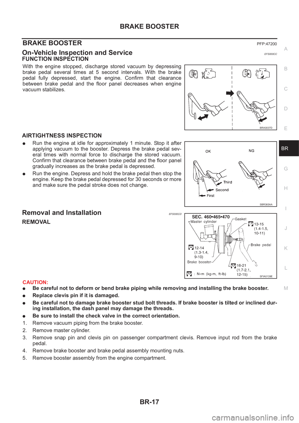
With the engine stopped, discharge stored vacuum by depressing
brake pedal several times at 5 second intervals. With the brake
pedal fully depressed, start the engine. Confirm that clearance
between brake pedal and the floor panel decreases when engine
vacuum stabilizes.
AIRTIGHTNESS INSPECTION
●Run the engine at idle for approximately 1 minute. Stop it after
applying vacuum to the booster. Depress the brake pedal sev-
eral times with normal force to discharge the stored vacuum.
Confirm that clearance between brake pedal and the floor panel
gradually increases as the brake pedal is depressed.
●Run the engine. Depress and hold the brake pedal then stop the
engine. Keep the brake pedal depressed for 30 seconds or more
and make sure the pedal stroke does not change.
Removal and InstallationEFS000CD
REMOVAL
CAUTION:
●Be careful not to deform or bend brake piping while removing and installing the brake booster.
●Replace clevis pin if it is damaged.
●Be careful not to damage brake booster stud bolt threads. If brake booster is tilted or inclined dur-
ing installation, the dash panel may damage the threads.
●Be sure to install the check valve in the correct orientation.
1. Remove vacuum piping from the brake booster.
2. Remove master cylinder.
3. Remove snap pin and clevis pin on passenger compartment clevis. Remove input rod from the brake
pedal.
4. Remove brake booster and brake pedal assembly mounting nuts.
5. Remove booster assembly from the engine compartment.
BRA0037D
SBR365AA
SFIA0139E
Page 2760 of 3833
BR-20
VACUUM LINES
CHECK VALVE INSPECTION
Airtightness Inspection
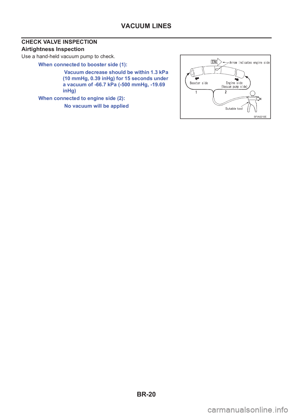
Use a hand-held vacuum pump to check.
When connected to booster side (1):
Vacuum decrease should be within 1.3 kPa
(10 mmHg, 0.39 inHg) for 15 seconds under
a vacuum of -66.7 kPa (-500 mmHg, -19.69
inHg)
When connected to engine side (2):
No vacuum will be applied
SFIA0210E
Page 2786 of 3833
BRC-2
4WD ACTUATOR RELAY (4WD SOLENOID
A C T U AT O R R E L AY ) T U R N S O N / O F F F R E -
QUENTLY ............................................................ 42
ABS Warning Lamp Does Not Illuminate. (ABS
Warning Lamp Does Not Come On When The Igni-
tion Switch Is Turned ON.) ...................................... 42
ABS Warning Lamp Illuminates With Ignition ON,
But Does Not Illuminates After A Few Seconds.
(ABS Warning Lamp Has Illuminated.) ................... 42
4WD Warning Lamp Does Not Illuminate With Igni-
tion ON. .................................................................. 43
4WD Warning Lamp Does Not Go Out Several Sec-
onds After Engine Is Started. (Drive Mode Indicator
Lamp Goes Out.) .................................................... 43
Heavy Tight-corner Braking Symptom Occurs
When The Vehicle Is Driven In Auto Mode And The
Steering Wheel Is Turned Fully To Either Side After
The Engine Is Started. ............................................ 44
Drive Modes Cannot Be Switched After Engine Is
Started. ................................................................... 45
Wheel Driving, 4WD Warning Lamp Flashes Rap-
idly. (When It Flashes For Approx. One Minute, Then
Does Not Illuminate.) .............................................. 45
Wheel Driving, 4WD Warning Lamp Flashes Slowly.
(When It Continues To Illuminate Until Engine Turns
OFF.) ....................................................................... 45
Vehicle Does Not Enter 4WD Mode Even Though
4WD Warning Lamp Is OFF. ................................... 46
Tight-corner Braking Symptom Occurs When The
Vehicle Is Started In Auto Mode (4WD Warning
Lamp Remain OFF). ............................................... 46
E-TS Actuator Relay (4WD Solenoid Actuator
Relay) Turns ON/OFF Frequently. .......................... 46
Inspection Of Drive Mode Change-over Switch Path ... 47
4WD/ABS CONTROL UNIT ...................................... 48
Removal and Installation ........................................ 48
REMOVAL ........................................................... 48
INSTALLATION .................................................... 48
WHEEL SENSORS ................................................... 49
Removal and Installation ........................................ 49
G-SENSOR (4WD MODEL ONLY) ............................ 50
Removal and Installation ........................................ 50
SENSOR ROTOR ................................................... ... 51
Removal and Installation ........................................ 51
REMOVAL ........................................................... 51
INSTALLATION .................................................... 51
ACTUATOR ............................................................... 52
Removal and Installation ........................................ 52
REMOVAL ........................................................... 53
INSTALLATION .................................................... 53
ESP/TCS/ABS
PRECAUTIONS ......................................................... 54
Precautions for Brake System ................................ 54
Precautions for Brake Control ................................ 54
Precautions for CAN System .................................. 54
FOR INSPECTION .............................................. 54
FOR HARNESS REPAIR .................................... 55PREPARATION ......................................................... 56
Special Service Tool ................................................ 56
Commercial Service Tool ........................................ 56
ON-VEHICLE SERVICE ............................................ 57
Adjustment of Neutral Position of Steering Wheel
Angle Sensor .......................................................... 57
GENERAL INFORMATION ....................................... 59
Fail-Safe .................................................................. 59
ABS SYSTEM ...................................................... 59
ESP/TCS SYSTEM .............................................. 59
Hydraulic Circuit ...................................................... 59
ABS Functions ........................................................ 59
TCS Functions ........................................................ 60
ESP Functions ........................................................ 60
System Diagram ..................................................... 61
CAN COMMUNICATION ........................................... 62
System Description ................................................. 62
FOR A/T MODELS ............................................... 62
FOR M/T MODELS .............................................. 62
TROUBLE DIAGNOSIS ............................................ 64
How to Perform Trouble Diagnoses for Quick and
Accurate Repair ...................................................... 64
INTRODUCTION ................................................. 64
WORK FLOW ...................................................... 65
ASKING COMPLAINTS ....................................... 66
EXAMPLE OF DIAGNOSIS SHEET .................... 66
Component Parts and Harness Connector Location ... 67
Schematic ............................................................... 68
Wiring Diagram —ESP/TCS/ABS— ..................... 69
Control Unit Input/Output Signal Standard .............. 75
STANDARDS USING A CIRCUIT TESTER AND
OSCILLOSCOPE ................................................. 75
STANDARDS WITH CONSULT-II ........................ 78
Functions of CONSULT-II ....................................... 80
CONSULT-II MAINLY FUNCTION APPLICA-
TION TO ESP/TCS/ABS ...................................... 80
SELF-DIAGNOSIS ............................................... 81
DATA MONITOR .................................................. 83
ACTIVE TEST ...................................................... 87
For Correct and Quick Diagnosis ............................ 90
PRECAUTIONS FOR TROUBLE DIAGNOSIS ... 90
Basic Inspection ...................................................... 91
PRELIMINARY CHECK 1: (BRAKE FLUID
LEVEL AND LEAK INSPECTION) ....................... 91
PRELIMINARY CHECK 2: (INSPECTION FOR
LOOSE POWER SUPPLY TERMINAL) ............... 92
PRELIMINARY CHECK 3: (INSPECTION FOR
ABS WARNING LAMP, ESP OFF INDICATOR
LAMP, AND SLIP INDICATOR LAMP) ................. 92
Inspection 1 Wheel Sensor and Circuit ................... 92
Inspection 2 Engine System ................................... 94
Inspection 3 ESP/TCS/ABS Control Unit System ... 94
Inspection 4 Pressure Sensor and the Circuit
between Pressure Sensor and ESP/TCS/ABS Con-
trol Unit. ................................................................... 95
Inspection 5 Steering wheel Angle Sensor and the
Circuit between Steering Wheel Angle Sensor and
ESP/TCS/ABS Control Unit. ................................... 96
Inspection 6 Yaw Rate Sensor and Side G sensor
Page 2790 of 3833
![NISSAN X-TRAIL 2001 Service Repair Manual BRC-6
[4WD/ABS]
ALL MODE 4X4 SYSTEM
ALL MODE 4X4 SYSTEM
PFP:47850
System DescriptionEFS001CJ
ABS FUNCTION
●During ABS operation, brake pedal lightly vibrates and its mechanical noise may be heard. T NISSAN X-TRAIL 2001 Service Repair Manual BRC-6
[4WD/ABS]
ALL MODE 4X4 SYSTEM
ALL MODE 4X4 SYSTEM
PFP:47850
System DescriptionEFS001CJ
ABS FUNCTION
●During ABS operation, brake pedal lightly vibrates and its mechanical noise may be heard. T](/manual-img/5/57405/w960_57405-2789.png)
BRC-6
[4WD/ABS]
ALL MODE 4X4 SYSTEM
ALL MODE 4X4 SYSTEM
PFP:47850
System DescriptionEFS001CJ
ABS FUNCTION
●During ABS operation, brake pedal lightly vibrates and its mechanical noise may be heard. This is a nor-
mal condition.
●When starting engine, or just after starting vehicle, brake pedal may vibrate. Also motor operating noise
may be heard from engine compartment. This is a normal status of operation check.
● When vehicle drives on rough, gravel, or snowy (fresh deep snow) road, the following conditions occur.
Stopping distance may be longer than that of vehicles without ABS.
4WD FUNCTION
● Electronically controlled 4WD is controlled by the same control module as that for ABS (4WD/ABS control
unit). 4WD/ABS control unit controls both electronically-controlled 4WD and ABS, based on input signals
from several sensors.
●If electrical system-related malfunction occurred in 4WD/ABS system, control unit illuminates the following
lamps: 4WD warning lamp and/or ABS warning lamp on meter control unit assembly. This notifies driver of
malfunction. At the same time, control unit indicates malfunctioning part detected by self-diagnosis with
flashing pattern of LED. Indication on electronic system diagnosis tester (CONSULT) corresponds to this
flashing pattern as shown below.
Control System DiagramEFS001CK
Self-diagnostic test mode Remarks
Result of self-diagnosis Conformable to 4WD/ABS
Data monitor Conformable to 4WD/ABS
Active testChecks ABS solenoid valve ON/OFF, ABS motor ON/OFF, 4WD sole-
noid
Control unit part No. 4WD/ABS control unit
SFIA0350E
Page 2802 of 3833
![NISSAN X-TRAIL 2001 Service Repair Manual BRC-18
[4WD/ABS]
TROUBLE DIAGNOSIS
Trouble Diagnosis Chart by Symptom
EFS001BF
When ABS and 4WD warning lamps illuminate, perform self-diagnosis.
Symptom Condition Check items Reference page
4wd indic NISSAN X-TRAIL 2001 Service Repair Manual BRC-18
[4WD/ABS]
TROUBLE DIAGNOSIS
Trouble Diagnosis Chart by Symptom
EFS001BF
When ABS and 4WD warning lamps illuminate, perform self-diagnosis.
Symptom Condition Check items Reference page
4wd indic](/manual-img/5/57405/w960_57405-2801.png)
BRC-18
[4WD/ABS]
TROUBLE DIAGNOSIS
Trouble Diagnosis Chart by Symptom
EFS001BF
When ABS and 4WD warning lamps illuminate, perform self-diagnosis.
Symptom Condition Check items Reference page
4wd indicator lamp does not come on
for approximately 1 second when the
ignition switch is turned on.IGN-ON
●Blown drive mode indicator lamp bulb
●Blown fuse between ignition and drive mode
indicator lamp
●Open circuit of wiring between ignition and
drive mode indicator lampBRC-42
ABS warning lamp does not illuminate
with ignition ON. (ABS warning lamp
check)IGN-ON
●Blown ABS warning lamp bulb
●Blown fuse between ignition and ABS warning
lamp.
●Open circuit of wiring between ignition and
ABS warning lamp.
●Malfunction in ABS systemBRC-42
ABS warning lamp illuminates with
ignition ON, but does not illuminates
after a few seconds. (ABS warning
lamp has not illuminated.)IGN-ON●4WD/ABS control unit connector discon-
nected
●Malfunction in ABS systemBRC-42
4WD warning lamp does not illuminate
with ignition ON.IGN-ON
●Blown 4WD warning lamp bulb
●Blown fuse between ignition and 4WD warn-
ing lamp
●Open circuit in wire between ignition and 4WD
warning lamp
●Open circuit in wire between 4WD warning
lamp and 4WD actuator relay
●Disconnected 4WD actuator relay
●Open circuit in wire between 4WD actuator
relay and body groundBRC-43
4WD warning lamp does not go out
several seconds after engine is started.
(Drive mode indicator lamp goes out.)Engine running●4WD/ABS control unit connector discon-
nected
●Malfunction present in 4WD systemBRC-43
Heavy tight-corner braking symptom
occurs when vehicle is driven in the fol-
lowing conditions: AUTO mode and
steering wheel is turned fully to either
sides after engine is started (Note 1,
Note 2).●Engine run-
ning
●AUTO mode
●Steering
wheel fully
turned
●Operation is not in AUTO mode (in 2WD or
LOCK mode).
●Throttle position signal error
●Mechanical malfunction of electronically con-
trolled coupling
●Malfunction present in 4WD systemBRC-44
Drive modes cannot be switched after
engine is started.Engine running
●Drive mode change-over switch is discon-
nected.
●Open circuit between drive mode change-over
switch and 4WD /ABS control unit
●Open circuit between drive mode change-over
switch and body groundBRC-45
Vehicle running, 4WD warning lamp
flashes rapidly. (When it flashes for
Approx. One minute, then does not illu-
minate.) Rapid flashing: Two times
flashing per 1 secondEngine running
(to other than
2WD mode)Protection function was activated due to heavy
load to electronically controlled coupling. (4WD
system is not malfunctioning.)BRC-45
Page 2803 of 3833
![NISSAN X-TRAIL 2001 Service Repair Manual TROUBLE DIAGNOSIS
BRC-19
[4WD/ABS]
C
D
E
G
H
I
J
K
L
MA
B
BRC
CAUTION:
1. Light tight-corner braking symptom may occur depending on driving conditions in AUTO mode.
This is not malfunction NISSAN X-TRAIL 2001 Service Repair Manual TROUBLE DIAGNOSIS
BRC-19
[4WD/ABS]
C
D
E
G
H
I
J
K
L
MA
B
BRC
CAUTION:
1. Light tight-corner braking symptom may occur depending on driving conditions in AUTO mode.
This is not malfunction](/manual-img/5/57405/w960_57405-2802.png)
TROUBLE DIAGNOSIS
BRC-19
[4WD/ABS]
C
D
E
G
H
I
J
K
L
MA
B
BRC
CAUTION:
1. Light tight-corner braking symptom may occur depending on driving conditions in AUTO mode.
This is not malfunction.
2. Heavy tight-corner braking symptom occurs when vehicle is driven in the following conditions:
LOCK mode, steering wheel is turned fully to either sides, and accelerator pedal was depressed.
4WD/ABS Control Unit Input/Output Signal StandardEFS001BG
4WD/ABS CONTROL UNIT CONNECTOR TERMINAL ARRANGEMENT
CAUTION:
When ignition switch is turned to ON with connectors of 4WD/ABS control unit and actuator con-
nected.
REFERENCE STANDARD TABLE
Specifications defined by circuit tester
Vehicle running, 4WD warning lamp
flashes slowly. (When it flashes for
Approx. One minute, then does not illu-
minate.) slow flashing: One flashing
per 2 seconds●Engine run-
ning
●Driving at
vehicle speed
30km/h (19
MPH)Tire size is different for front and rear of vehicle.BRC-45
Vehicle does not enter 4WD mode
even though 4WD warning lamp is off.Engine runningMechanical malfunction of electronically con-
trolled coupling (Mechanical engagement of
clutch is not possible.)BRC-46
Symptom Condition Check items Reference page
SFIA0351E
Te r m i n a l N o .
Location Standard (note 1)(Note) Check
points when result
was malfunctioning +–
3.
109Power supply Ignition switch ONB a t t e ry v o lta g e ( A p p ro x .
12V)Control unit power
supply circuit