2001 NISSAN X-TRAIL check engine
[x] Cancel search: check enginePage 2659 of 3833
TROUBLE DIAGNOSIS
TF-49
C
E
F
G
H
I
J
K
L
MA
B
TF
4WD solenoid valve
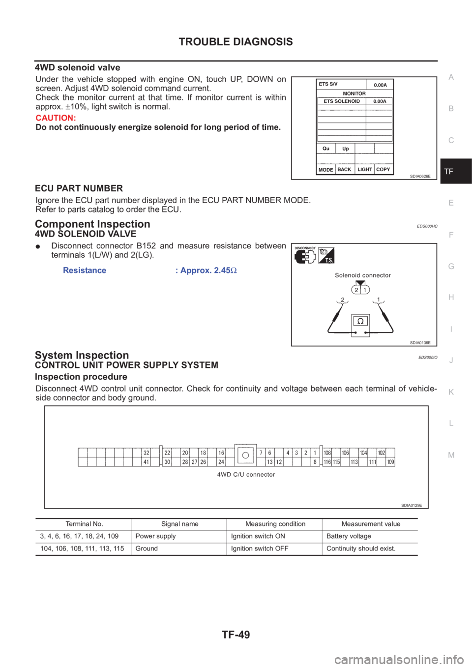
Under the vehicle stopped with engine ON, touch UP, DOWN on
screen. Adjust 4WD solenoid command current.
Check the monitor current at that time. If monitor current is within
approx. ±10%, light switch is normal.
CAUTION:
Do not continuously energize solenoid for long period of time.
ECU PART NUMBER
Ignore the ECU part number displayed in the ECU PART NUMBER MODE.
Refer to parts catalog to order the ECU.
Component InspectionEDS000HC
4WD SOLENOID VALVE
●Disconnect connector B152 and measure resistance between
terminals 1(L/W) and 2(LG).
System InspectionEDS000IO
CONTROL UNIT POWER SUPPLY SYSTEM
Inspection procedure
Disconnect 4WD control unit connector. Check for continuity and voltage between each terminal of vehicle-
side connector and body ground.
SDIA0626E
Resistance : Approx. 2.45Ω
SDIA0136E
Terminal No. Signal name Measuring condition Measurement value
3, 4, 6, 16, 17, 18, 24, 109 Power supply Ignition switch ON Battery voltage
104, 106, 108, 111, 113, 115 Ground Ignition switch OFF Continuity should exist.
SDIA0129E
Page 2666 of 3833
TF-56
TROUBLE DIAGNOSIS
2. COMBINATION METER POWER SUPPLY CIRCUIT INSPECTION
1. Disconnect combination meter connector.
2. Check voltage between the combination meter harness connector M46 terminal No. LHD models: 46 (W/
L) RHD models: 59 (W/L) and body ground.
OK or NG
OK >> Malfunctioning combination meter.
NG >> Check fuse 10A [#11] to combination meter harness and connector.
4WD WARNING LAMP DOES NOT GO OUT SEVERAL SECONDS AFTER ENGINE
STARTED.(4WD MODE INDICATOR LAMP GOES OUT)
1. PERFORM SELF-DIAGNOSIS
Using CONSULT-II perform self-diagnosis.
OK or NG
OK >> No malfunction detected. Perform inspection again.
NG >>
●Determine the location of the malfunction according to the result of Self-diagnosis using CON-
SULT-II. (Malfunction is present in the 4WD system.)
●CONSULT-II does not display 4WD system-related trouble codes. GO TO 2.
2. 4WD CONTROL UNIT CONNECTOR CONNECTION INSPECTION
●Check 4WD control unit connector for proper connection.
OK or NG
OK >> Reconnect the 4WD control unit connector properly and perform inspection again.
NG >> Repair or replace the connector.
HEAVY TIGHT-CORNER BRAKING SYMPTOM OCCURS WHEN THE VEHICLE IS DRIVEN IN
AUTO MODE AND THE STEERING WHEEL IS TURNED FULLY TO EITHER SIDE AFTER THE
ENGINE IS STARTED
1. PERFORM SELF-DIAGNOSIS.
Using CONSULT-II perform self-diagnosis.
OK or NG
OK >> GO TO 2. (No self-diagnosis malfunction indicated.)
NG >> Determine the location of the malfunction according to the result of self-diagnosis using CON-
SULT-II. (Malfunction is present in the 4WD system.)
2. CHECK USING THE DATA MONITOR FUNCTION OF THE CONSULT- II.
●Perform inspection by the data monitor function of the CONSULT-II.
●Check that the operation is in AUTO mode.
●Measure voltage when the accelerator pedal is not depressed. (Accelerator pedal not depressed: approx.
0.5V or lower)
●Measure the current supplied to the 4WD solenoid valve. (Accelerator pedal not depressed: approx. 0A)
OK or NG
OK >> GO TO 3. (No self-diagnosis malfunction indicated.)
NG >>
●Not in AUTO mode. GO TO 3.
●Voltage when accelerator pedal is not depressed is higher than approximately 0.5V.
●4WD solenoid valve current when the accelerator pedal is not depressed is other than 0A.
●Countermeasure: Keep the vehicle idling for approximately 15 minutes before checking again.
(Voltage when accelerator pedal is not depressed will be automatically reset to zero during this
period.)
Page 2667 of 3833
TROUBLE DIAGNOSIS
TF-57
C
E
F
G
H
I
J
K
L
MA
B
TF
3.INSPECTION USING 4WD MODE CHANGE-OVER SWITCH
●On data monitor screen of the CONSULT-II, check 4WD mode switch.
●Check if the display changes from ## to 2WD mode when the 2WD switch is pressed.
●Check if the display changes from ## to AUTO mode when the AUTO switch is pressed.
●Check if the display changes from ## to LOCK mode when the LOCK switch is pressed.
OK or NG
OK >> No malfunction detected.
NG >>
●Not in AUTO mode. (In 2WD or LOCK mode)
Countermeasure: Slightly depress the accelerator pedal and check that the operation mode
changes to LOCK mode.
●Check circuit between 4WD mode switch harness connector M39 terminal No.1 (BR) and
4WD control unit harness connector E122 terminal No. 27 (BR).
(AUTO mode is not available because a malfunction is present in the 2WD mode harness.)
NOTICE:
Mechanism of 4WD mode change-over.
●2WD mode: Operation changes to 2WD mode when 4WD control unit harness connector E122
terminal No. 27 (BR) is shorted to ground.
●AUTO mode: Operation changes to AUTO mode when 4WD control unit harness connector
E122 terminals No. 27 (BR) and No. 26 (L) is shorted to ground.
●LOCK mode: Operation changes to LOCK mode when 4WD control unit harness connector
E122 terminal No. 26 (L) is shorted to ground.
4WD MODES CANNOT BE SWITCHED AFTER ENGINE IS STARTED
1.INSPECTION USING 4WD MODE CHANGE-OVER SWITCH
●Drive modes cannot be switched after the engine is started.
●On data monitor screen of the CONSULT-II, check 4WD mode switch.
●Check if the display changes from ## to 2WD mode when the 2WD switch is pressed.
●Check if the display changes from ## to AUTO mode when the AUTO switch is pressed.
●Check if the display changes from ## to LOCK mode when the LOCK switch is pressed.
OK or NG
OK >> No malfunction detected.
NG >>
●CONSULT-II display does not change from ## when the 2WD switch is pressed. Check harness
of the 2WD switch.
●CONSULT-II display does not change from ## when the AUTO switch is pressed. Check har-
ness of the 2WD switch and LOCK switch.
●CONSULT-II display does not change from ## when the LOCK switch is pressed. Check har-
ness of the LOCK switch.
●Perform 4WD mode change-over switch inspection.
WHILE DRIVING, 4WD WARNING LAMP FLASHES RAPIDLY. (WHEN IT FLASHERS FOR
APPROX. ONE MINUTE, THEN DOES NOT ILLUMINATE.)
●While driving, 4WD warning lamp flashes rapidly. (when it flashes for approx. one minute, then does not
illuminate.)
Rapid flashing: 2 times/second
This phenomenon protects drivetrain parts when a heavy load is applied to the electronically controlled
coupling and multiple disc clutch temperature increases. It is not a malfunction.
When the difference of diameters by or with the front and rear wheel with AUTO mode the shift switch
occasionally changes to LOCK mode automatically. This is not a malfunction.
When the difference of revolution speed between the front and rear wheel with AUTO mode, the shift
switch occasionally changes to LOCK mode automatically. This is not a malfunction.
WHILE DRIVING, 4WD WARNING LAMP FLASHES SLOWLY. (WHEN IT CONTINUES TO ILLU-
MINATE UNTIL ENGINE TURNS OFF.)
1. Check using the data monitor function of the CONSULT-II.
Page 2668 of 3833
TF-58
TROUBLE DIAGNOSIS
●Perform inspection with the data monitor function of the CONSULT- I I .
●Check if the value of IMPROPER SIZE TIRE MONITOR is 8 mm (0.31 in) or more.
●Stop the engine. Restart the engine and drive the vehicle at 20 km/h (12 MPH) or faster for approxi-
mately 200 seconds. Confirm the 4WD warning lamp flashes slowly.
(Check if the value of IMPROPER SIZE TIRE MONITOR is 8 mm (0.31 in) or more.)
When the tire size is normal, the value of IMPROPER SIZE TIRE MONITOR will change from 8 mm
(0.31 in) or more to 0 to 4 mm (0 to 0.16 in) (normal condition) after the vehicle is driven 20 km/h (12
MPH) or faster for approximately 5 seconds.
2. Tire inspection
●Inspection of tire pressure.
●Wear condition.
●Check size of the front and rear tires. (No excessive difference should be observed.)
VEHICLE DOES NOT ENTER 4WD MODE EVEN THOUGH 4WD WARNING LAMP IS OFF.
1. Check using the data monitor function of the CONSULT-II.
Perform inspection by the data monitor function of the CONSULT-II.
–Check if the vehicle operation changes to 2WD, AUTO, and LOCK modes.
–Check current supplied to the 4WD solenoid valve in AUTO mode.
2. Check using the active test function of the CONSULT-II.
Using active test mode of CONSULT-II, supply current to the 4WD solenoid valve and check that the mon-
itor current becomes close to this supply current.
●The 4WDcontrol unit is normal when the difference between 4WD solenoid valve current and the monitor
current is within ±10%.
It is necessary to inspect the electronically controlled coupling assembly.
TIGHT-CONER BRAKING SYMPTOM OCCURS WHEN THE VEHICLE IS STARTED IN AUTO
WARNING LAMP REMAIN OFF).
1. THROTTLE POSITION SENSOR AND HARNESS INSPECTION
Check accelerator pedal stroke.
OK or NG
OK >> Perform self-diagnosis again.
NG >> Malfunctioning throttle position sensor harness.
4WD ACTUATOR RELAY (4WD SOLENOID ACTUATOR RELAY) TURNS ON/OFF FREQUENTLY
1. SELF-DIAGNOSIS RESULT IS 4WD ACTUATOR RELAY (4WD SOLENOID ACTUATOR RELAY) ON
ERROR AND OFF ERROR.
Is self-diagnosis result [ON error and OFF error]?
OK or NG
OK >> GO TO 2.
NG >> Repair or replace as necessary.
2. 4WD ACTUATOR RELAY (4WD SOLENOID ACTUATOR RELAY) AND HARNESS INSPECTION
Is self-diagnosis result [ON error and OFF error]?
OK or NG
OK >> Perform self-diagnosis again.
NG >> Malfunctioning 4WD actuator relay (4WD solenoid actuator relay) harness. Accelerator pedal not
depressed:Approx. 0A
Accelerator pedal
depressed:Approx. 2.8A
Example) Monitor value becomes approx. 1A for 4WD solenoid current 1A setting.
Page 2678 of 3833
RFD-2
PRECAUTIONS
PRECAUTIONS
PFP:00001
CautionEDS00101
●Before starting diagnosis of the vehicle, understand symptoms well. Perform correct and systematic oper-
ations.
●Check for the correct installation status prior to removal or disassembly. When mating marks are required,
be sure they do not interfere with the function of the parts they are applied to.
●Carry out an overhaul in a clean work place. Using a dust proof room is recommended.
●Before disassembly, using steam or white gasoline, completely remove sand and mud from the exterior of
the unit, preventing them from entering into the unit during disassembly or assembly.
●Check appearance of the disassembled parts for damage, deformation, and abnormal wear. If a malfunc-
tion is detected, replace it with a new one.
●Normally replace lock pins, oil seals, and bearings with new ones every time they are removed.
●In principle, tighten bolts or nuts gradually in several steps working diagonally from inside to outside. If
tightening sequence is specified, observe it.
●Clean and flush the parts sufficiently and blow them dry.
●Be careful not to damage the sliding surfaces and mating surfaces.
●When applying sealant, remove the old sealant from the mounting surface; then remove any moisture, oil,
and foreign materials from the application and mounting surfaces.
●Always use shop paper for cleaning the inside of components.
●Avoid using cotton gloves or a shop cloth to prevent entering of lint.
●During assembly, observe the specified tightening torque, and apply new differential oil, Vaseline, or Nis-
san MP Special Grease No. 2, as specified for each vehicle, when necessary.
●Do not reuse drained oil. Discard waste oil after oil changes or part treatment in accordance with local
laws and regulations.
Precautions for Brake SystemEDS00102
●When installing rubber parts, final tightening must be carried out under unladen condition* with tires on
ground.
*: Fuel, radiator coolant and engine oil full. Spare tire, jack, hand tools and mats in designated positions.
●After installing removed suspension parts, check wheel alignment and adjust if necessary.
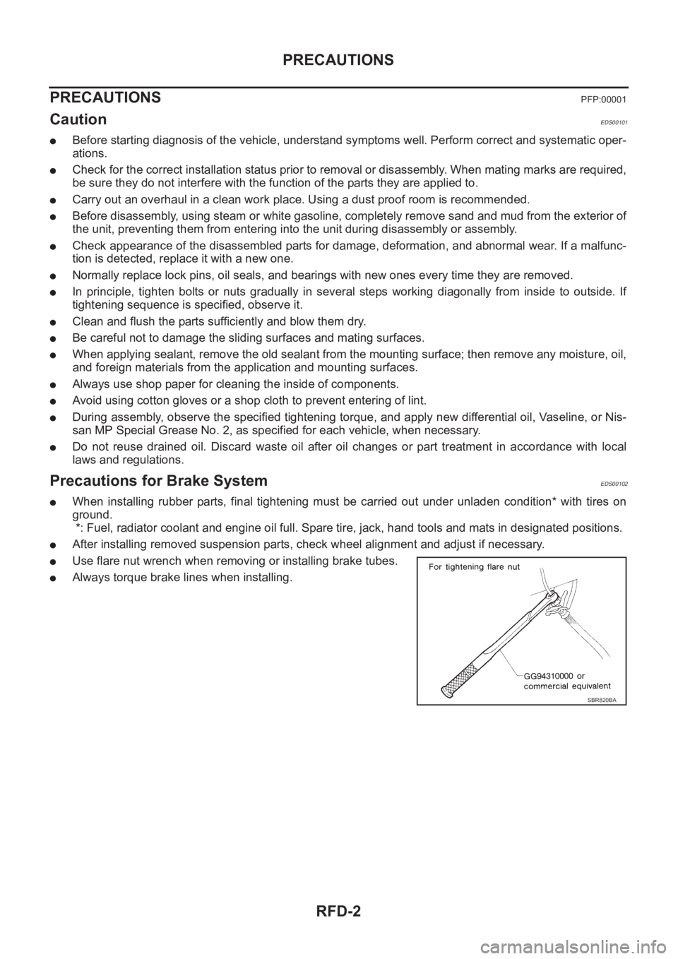
●Use flare nut wrench when removing or installing brake tubes.
●Always torque brake lines when installing.
SBR820BA
Page 2718 of 3833
FSU-12
FRONT SUSPENSION MEMBER
FRONT SUSPENSION MEMBER
PFP:54401
Removal and InstallationEES00078
REMOVAL
1. Remove tires. Raise vehicle.
2. Remove mounting nuts on lower portion of stabilizer connecting rod from transverse link.
3. Remove transverse link from suspension member, and move the transverse link outward.
4. Remove front exhaust tube mounting rubber from suspension member.
5. Support engine or transmission with a transmission jack.
6. Remove center member from vehicle. Refer to TF-11, "
TRANSFER ASSEMBLY"
7. Remove steering gear mounting bolts. Remove steering gear and power steering tube bracket from sus-
pension member.
8. Hang steering gear.
9. Remove rear engine mount insulator from suspension member.
10. Remove body-side mounting bolts from member pin stay.
11. Set a transmission jack under suspension member, and remove suspension member mounting nuts.
12. Slowly lower transmission jack to remove suspension member from vehicle.
INSTALLATION
●Refer to FSU-5, "Components" for tightening torque in the reverse order of removal.
●After installation, perform final tightening of each part under unladen conditions with tires on ground.
Check wheel alignment. Refer to FSU-6, "
Wheel Alignment" .
Page 2746 of 3833
BR-6
BRAKE PEDAL
BRAKE PEDAL
PFP:46501
On-Vehicle Inspection and AdjustmentEFS000C1
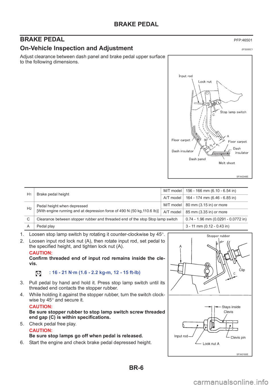
Adjust clearance between dash panel and brake pedal upper surface
to the following dimensions.
1. Loosen stop lamp switch by rotating it counter-clockwise by 45°.
2. Loosen input rod lock nut (A), then rotate input rod, set pedal to
the specified height, and tighten lock nut (A).
CAUTION:
Confirm threaded end of input rod remains inside the cle-
vis.
3. Pull pedal by hand and hold it. Press stop lamp switch until its
threaded end contacts the stopper rubber.
4. While holding it against the stopper rubber, turn the switch clock-
wise by 45° and secure it.
CAUTION:
Be sure stopper rubber to stop lamp switch screw threaded
end gap (C) is within specifications.
5. Check pedal free play.
CAUTION:
Be sure stop lamps go off when pedal is released.
6. Start the engine and check brake pedal depressed height.
SFIA0348E
H1Brake pedal heightM/T model 156 - 166 mm (6.10 - 6.54 in)
A/T model 164 - 174 mm (6.46 - 6.85 in)
H
2Pedal height when depressed
[With engine running and at depression force of 490 N (50 kg,110.6 lb)]M/T model 80 mm (3.15 in) or more
A/T model 85 mm (3.35 in) or more
C Clearance between stopper rubber and threaded end of the stop Stop lamp switch 0.74 - 1.96 mm (0.0291 - 0.0772 in)
A Pedal play3 - 11 mm (0.12 - 0.43 in)
: 16 - 21 N·m (1.6 - 2.2 kg-m, 12 - 15 ft-lb)
SFIA0160E
Page 2747 of 3833
BRAKE PEDAL
BR-7
C
D
E
G
H
I
J
K
L
MA
B
BR
ComponentsEFS001CI
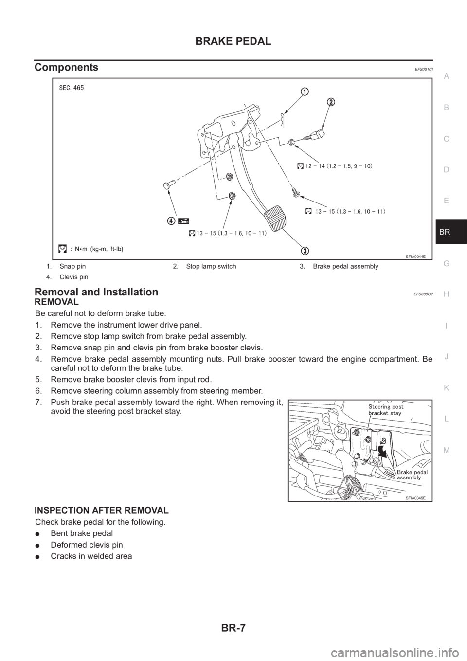
Removal and InstallationEFS000C2
REMOVAL
Be careful not to deform brake tube.
1. Remove the instrument lower drive panel.
2. Remove stop lamp switch from brake pedal assembly.
3. Remove snap pin and clevis pin from brake booster clevis.
4. Remove brake pedal assembly mounting nuts. Pull brake booster toward the engine compartment. Be
careful not to deform the brake tube.
5. Remove brake booster clevis from input rod.
6. Remove steering column assembly from steering member.
7. Push brake pedal assembly toward the right. When removing it,
avoid the steering post bracket stay.
INSPECTION AFTER REMOVAL
Check brake pedal for the following.
●Bent brake pedal
●Deformed clevis pin
●Cracks in welded area
1. Snap pin 2. Stop lamp switch 3. Brake pedal assembly
4. Clevis pin
SFIA0044E
SFIA0349E