2001 NISSAN X-TRAIL check engine
[x] Cancel search: check enginePage 2079 of 3833

AT-1
AUTOMATIC TRANSAXLE
C TRANSMISSION/TRANSAXLE
CONTENTS
D
E
F
G
H
I
J
K
L
M
SECTION
A
B
AT
AUTOMATIC TRANSAXLE
PRECAUTIONS .......................................................... 5
Precautions for Supplemental Restraint System
(SRS) “AIR BAG” and “SEAT BELT PRE-TEN-
SIONER” .................................................................. 5
Precautions for On Board Diagnostic (EURO-OBD)
System of A/T and Engine — Euro-OBD — ............. 5
Precautions for Trouble Diagnosis ........................... 5
Precautions for Harness Repair ............................... 5
Precautions .............................................................. 6
Service Notice or Precautions .................................. 7
Wiring Diagrams and Trouble Diagnosis .................. 8
PREPARATION ........................................................... 9
Special Service Tools ............................................... 9
Commercial Service Tools ...................................... 12
A/T FLUID ................................................................. 13
Checking A/T Fluid ................................................. 13
Changing A/T Fluid ............................................. ... 13
OVERALL SYSTEM ................................................. 14
A/T Electrical Parts Location .................................. 14
Circuit Diagram ...................................................... 15
Cross-Sectional View ............................................. 16
Hydraulic Control Circuit ........................................ 17
Shift Mechanism ..................................................... 18
Control System ....................................................... 28
Control Mechanism ................................................ 29
Control Valve .......................................................... 34
EURO-OBD
TROUBLE DIAGNOSIS — INDEX ........................... 35
Alphabetical & P No. Index for DTC ....................... 35
ON BOARD DIAGNOSTIC SYSTEM DESCRIP-
TION .......................................................................... 37
Introduction ............................................................ 37
EURO-OBD Function for A/T System .................... 37
One or Two Trip Detection Logic of EURO-OBD ... 37
EURO-OBD Diagnostic Trouble Code (DTC) ......... 37
Malfunction Indicator lamp (MIL) ............................ 41
CONSULT-II ........................................................... 41
Diagnostic Procedure Without CONSULT-II ........... 50TROUBLE DIAGNOSIS — INTRODUCTION ........... 56
Introduction ............................................................. 56
Work Flow ............................................................... 60
TROUBLE DIAGNOSIS — BASIC INSPECTION .... 63
A/T Fluid Check ...................................................... 63
Stall Test ................................................................. 64
Line Pressure Test .................................................. 67
Road Test ............................................................... 68
TROUBLE DIAGNOSIS — GENERAL DESCRIP-
TION .......................................................................... 86
Symptom Chart ....................................................... 86
TCM Terminals and Reference Value ...................106
CAN COMMUNICATION .........................................109
System Description ...............................................109
DTC P0705 PARK/NEUTRAL POSITION (PNP)
SWITCH ..................................................................110
Description ............................................................110
Wiring Diagram — AT — PNP/SW .......................112
Diagnostic Procedure ...........................................113
Component Inspection ..........................................115
DTC P0710 A/T FLUID TEMPERATURE SENSOR
CIRCUIT ..................................................................116
Description ............................................................116
Wiring Diagram — AT — FTS ..............................118
Diagnostic Procedure ...........................................119
Component Inspection ..........................................121
DTC P0720 VEHICLE SPEED SENSOR·A/T (REV-
OLUTION SENSOR) ...............................................122
Description ............................................................122
Wiring Diagram — AT — VSSA/T ........................124
Diagnostic Procedure ...........................................125
DTC P0725 ENGINE SPEED SIGNAL ...................127
Description ............................................................127
Wiring Diagram — AT — ENGSS .........................128
Diagnostic Procedure ...........................................129
DTC P0731 A/T 1ST GEAR FUNCTION ...............
.131
Description ............................................................131
Wiring Diagram — AT — 1ST ...............................134
Diagnostic Procedure ...........................................135
Component Inspection ..........................................136
Page 2080 of 3833

AT-2
DTC P0732 A/T 2ND GEAR FUNCTION ................137
Description ............................................................137
Wiring Diagram — AT — 2ND ..............................140
Diagnostic Procedure ...........................................141
Component Inspection ..........................................142
DTC P0733 A/T 3RD GEAR FUNCTION ................143
Description ............................................................143
Wiring Diagram — AT — 3RD ..............................146
Diagnostic Procedure ...........................................147
Component Inspection ..........................................148
DTC P0734 A/T 4TH GEAR FUNCTION ................149
Description ............................................................149
Wiring Diagram — AT — 4TH ...............................152
Diagnostic Procedure ...........................................153
Component Inspection ..........................................156
DTC P0740 TORQUE CONVERTER CLUTCH
SOLENOID VALVE .................................................158
Description ............................................................158
Wiring Diagram — AT — TCV ..............................160
Diagnostic Procedure ...........................................161
Component Inspection ..........................................162
DTC P0745 LINE PRESSURE SOLENOID VALVE .163
Description ............................................................163
Wiring Diagram — AT — LPSV ............................165
Diagnostic Procedure ...........................................166
Component Inspection ..........................................168
DTC P0750 SHIFT SOLENOID VALVE A ...............170
Description ............................................................170
Wiring Diagram — AT — SSV/A ...........................172
Diagnostic Procedure ...........................................173
Component Inspection ..........................................174
DTC P0755 SHIFT SOLENOID VALVE B ...............175
Description ............................................................175
Wiring Diagram — AT — SSV/B ...........................177
Diagnostic Procedure ...........................................178
Component Inspection ..........................................179
DTC P1705 ACCELERATOR PEDAL POSITION
(APP) SENSOR .......................................................180
Description ............................................................180
Wiring Diagram — AT — TPS ..............................182
Diagnostic Procedure ...........................................183
DTC P1760 OVERRUN CLUTCH SOLENOID
VALVE .....................................................................185
Description ............................................................185
Wiring Diagram — AT — OVRCSV ......................187
Diagnostic Procedure ...........................................188
Component Inspection ..........................................189
DTC U1000 CAN COMMUNICATION LINE ...........
.190
Description ............................................................190
On Board Diagnosis Logic ....................................190
DTC Confirmation Procedure ...............................190
Wiring Diagram — AT — CAN ..............................191
Diagnostic Procedure ...........................................192
DTC BATT/FLUID TEMP SEN (A/T FLUID TEMP
SENSOR CIRCUIT AND TCM POWER SOURCE) .193
Description ............................................................193
Wiring Diagram — AT — BA/FTS .........................195
Diagnostic Procedure ...........................................196
Component Inspection ..........................................198DTC VEHICLE SPEED SENSOR MTR ...................199
Description ............................................................199
Wiring Diagram — AT — VSSMTR .......................201
Diagnostic Procedure ............................................202
DTC CONTROL UNIT (RAM), CONTROL UNIT
(ROM) ......................................................................203
Description ............................................................203
Diagnostic Procedure ............................................203
DTC CONTROL UNIT(EEPROM) ...........................205
Description ............................................................205
Diagnostic Procedure ............................................206
TROUBLE DIAGNOSES FOR SYMPTOMS ...........207
Wiring Diagram — AT — NONDTC ......................207
O/D OFF Indicator Lamp Does Not Come On ......209
Engine Cannot Be Started In “P” and “N” Position .211
In “P” Position, Vehicle Moves Forward Or Back-
ward When Pushed ...............................................212
In “N” Position, Vehicle Moves ..............................213
Large Shock. “N” → “R” Position ..........................214
Vehicle Does Not Creep Backward In “R” Position .215
Vehicle Does Not Creep Forward In “D”, “2” Or “1”
Position .................................................................218
Vehicle Cannot Be Started From D
1 .....................220
A/T Does Not Shift: D
1→ D2 Or Does Not Kickdown:
D
4→ D2 ...............................................................
.223
A/T Does Not Shift: D
2→ D3 ................................225
A/T Does Not Shift: D
3→ D4 ................................227
A/T Does Not Perform Lock-up .............................229
A/T Does Not Hold Lock-up Condition ..................230
Lock-up Is Not Released .......................................232
Engine Speed Does Not Return To Idle (Light Brak-
ing D
4→ D3 ) ........................................................233
Vehicle Does Not Start From D
1 ...........................234
A / T D o e s N o t S h i f t : D
4→ D3 , W h e n O v e r d r i v e C o n -
trol Switch “ON” → “OFF” .....................................236
A/T Does Not Shift: D
3→ 22 , W h e n S e l e c t o r L e v e r
“D” → “2” Position .................................................237
A/T Does Not Shift: 2
2→ 11 , When Selector Lever
“2” → “1” Position ..................................................238
Vehicle Does Not Decelerate By Engine Brake ....240
TCM Self-diagnosis Does Not Activate .................241
EXC.F/EURO-OBD
ON BOARD DIAGNOSTIC SYSTEM DESCRIP-
TION ........................................................................247
CONSULT-II ..........................................................247
Diagnostic Procedure Without CONSULT-II .........253
TROUBLE DIAGNOSIS — INTRODUCTION .........258
Introduction ...........................................................258
Work Flow .............................................................262
TROUBLE DIAGNOSIS — BASIC INSPECTION ...264
A/T Fluid Check ....................................................264
Stall Test ................................................................265
Line Pressure Test ................................................268
Road Test ..............................................................269
TROUBLE DIAGNOSIS — GENERAL DESCRIP-
Page 2091 of 3833

A/T FLUID
AT-13
D
E
F
G
H
I
J
K
L
MA
B
AT
A/T FLUIDPFP:KLE40
Checking A/T FluidECS004Q7
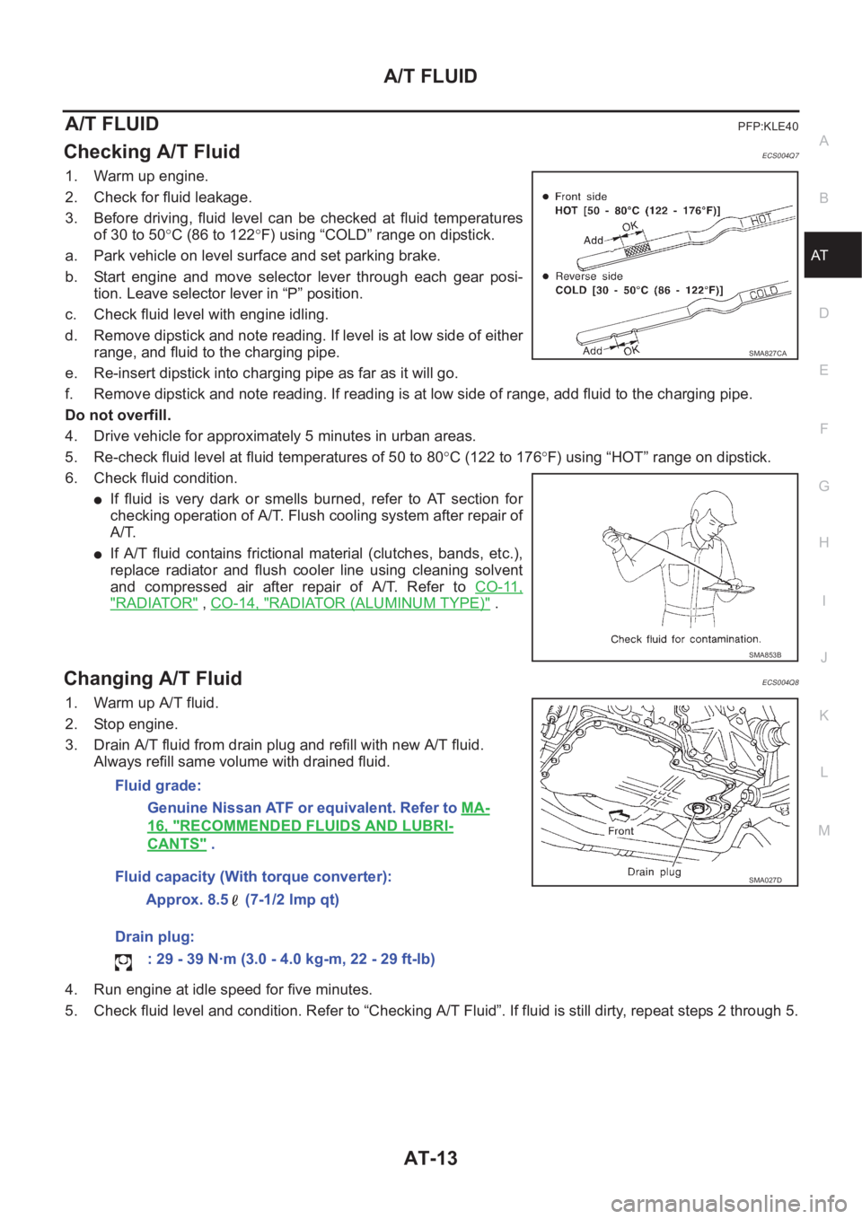
1. Warm up engine.
2. Check for fluid leakage.
3. Before driving, fluid level can be checked at fluid temperatures
of 30 to 50°C (86 to 122°F) using “COLD” range on dipstick.
a. Park vehicle on level surface and set parking brake.
b. Start engine and move selector lever through each gear posi-
tion. Leave selector lever in “P” position.
c. Check fluid level with engine idling.
d. Remove dipstick and note reading. If level is at low side of either
range, and fluid to the charging pipe.
e. Re-insert dipstick into charging pipe as far as it will go.
f. Remove dipstick and note reading. If reading is at low side of range, add fluid to the charging pipe.
Do not overfill.
4. Drive vehicle for approximately 5 minutes in urban areas.
5. Re-check fluid level at fluid temperatures of 50 to 80°C (122 to 176°F) using “HOT” range on dipstick.
6. Check fluid condition.
●If fluid is very dark or smells burned, refer to AT section for
checking operation of A/T. Flush cooling system after repair of
A/T.
●If A/T fluid contains frictional material (clutches, bands, etc.),
replace radiator and flush cooler line using cleaning solvent
and compressed air after repair of A/T. Refer to CO-11,
"RADIATOR" , CO-14, "RADIATOR (ALUMINUM TYPE)" .
Changing A/T FluidECS004Q8
1. Warm up A/T fluid.
2. Stop engine.
3. Drain A/T fluid from drain plug and refill with new A/T fluid.
Always refill same volume with drained fluid.
4. Run engine at idle speed for five minutes.
5. Check fluid level and condition. Refer to “Checking A/T Fluid”. If fluid is still dirty, repeat steps 2 through 5.
SMA827CA
SMA853B
Fluid grade:
Genuine Nissan ATF or equivalent. Refer to MA-
16, "RECOMMENDED FLUIDS AND LUBRI-
CANTS" .
Fluid capacity (With torque converter):
Approx. 8.5 (7-1/2 lmp qt)
Drain plug:
: 29 - 39 N·m (3.0 - 4.0 kg-m, 22 - 29 ft-lb)
SMA027D
Page 2112 of 3833

AT-34
OVERALL SYSTEM
Control Valve
ECS004QG
FUNCTION OF CONTROL VALVES
Valve name Function
Pressure regulator valve, plug
and sleeveRegulates oil discharged from the oil pump to provide optimum line pressure for all driving condi-
tions.
Pressure modifier valve and
sleeveUsed as a signal supplementary valve to the pressure regulator valve. Regulates pressure-modi-
fier pressure (signal pressure) which controls optimum line pressure for all driving conditions.
Pilot valve Regulates line pressure to maintain a constant pilot pressure level which controls lock-up mecha-
nism, overrun clutch, shift timing.
Accumulator control valve Regulates accumulator back-pressure to pressure suited to driving conditions.
Manual valve Directs line pressure to oil circuits corresponding to select positions.
Hydraulic pressure drains when the shift lever is in Neutral.
Shift valve A Simultaneously switches four oil circuits using output pressure of shift solenoid valve A to meet
driving conditions (vehicle speed, throttle opening, etc.).
Provides automatic downshifting and up-shifting (1st → 2nd → 3rd → 4th gears/4th → 3rd → 2nd
→ 1st gears) in combination with shift valve B.
Shift valve B Simultaneously switches three oil circuits using output pressure of shift solenoid valve B in rela-
tion to driving conditions (vehicle speed, throttle opening, etc.).
Provides automatic downshifting and up-shifting (1st → 2nd → 3rd → 4th gears/4th → 3rd → 2nd
→ 1st gears) in combination with shift valve A.
Overrun clutch control valve Switches hydraulic circuits to prevent engagement of the overrun clutch simultaneously with appli-
cation of the brake band in D
4 . (Interlocking occurs if the overrun clutch engages during D4 .)
1st reducing valve Reduces low & reverse brake pressure to dampen engine-brake shock when down-shifting from
the “1” position 1
2 to 11 .
Overrun clutch reducing valve Reduces oil pressure directed to the overrun clutch and prevents engine-brake shock.
In “1” and “2” positions, line pressure acts on the overrun clutch reducing valve to increase the
pressure-regulating point, with resultant engine brake capability.
Torque converter relief valve Prevents an excessive rise in torque converter pressure.
Torque converter clutch control
valve, plug and sleeveActivates or inactivates the lock-up function.
Also provides smooth lock-up through transient application and release of the lock-up system.
1-2 accumulator valve and piston Dampens the shock encountered when 2nd gear band servo contracts, and provides smooth
shifting.
3-2 timing valve Switches oil pressure with 3-2 timing valve according to throttle opening.
Shuttle control valve Reduces shock when down-shifting from 3rd to 2nd and regulates overrun clutch.
Cooler check valve Regulates oil pressure which causes lock-up when driving at low speeds.
Page 2113 of 3833
![NISSAN X-TRAIL 2001 Service Repair Manual TROUBLE DIAGNOSIS — INDEX
AT-35
[EURO-OBD]
D
E
F
G
H
I
J
K
L
MA
B
AT
[EURO-OBD]TROUBLE DIAGNOSIS — INDEXPFP:00000
Alphabetical & P No. Index for DTCECS003VK
ALPHABETICAL INDEX FOR DTC
Check if the NISSAN X-TRAIL 2001 Service Repair Manual TROUBLE DIAGNOSIS — INDEX
AT-35
[EURO-OBD]
D
E
F
G
H
I
J
K
L
MA
B
AT
[EURO-OBD]TROUBLE DIAGNOSIS — INDEXPFP:00000
Alphabetical & P No. Index for DTCECS003VK
ALPHABETICAL INDEX FOR DTC
Check if the](/manual-img/5/57405/w960_57405-2112.png)
TROUBLE DIAGNOSIS — INDEX
AT-35
[EURO-OBD]
D
E
F
G
H
I
J
K
L
MA
B
AT
[EURO-OBD]TROUBLE DIAGNOSIS — INDEXPFP:00000
Alphabetical & P No. Index for DTCECS003VK
ALPHABETICAL INDEX FOR DTC
Check if the vehicle is a model with Euro-OBD system or not by the “Type approval number” on the identifica-
tion plate. Refer toGI-43, "
IDENTIFICATION PLATE" .
●*1: These numbers are prescribed by SAE J2012.
●*2: When the fail-safe operation occurs, the MIL illuminates.
●*3: The MIL illuminates when both the “Revolution sensor signal” and the “Vehicle speed sensor signal” meet the fail-safe condition at
the same time.Type approval number Model
Available With Euro-OBD system
Not available (blank) Without Euro-OBD system
Items
(CONSULT-II screen terms)DTC
Reference page
CONSULT-II
GST*1
A/T 1ST GR FNCTN P0731AT-131, "
DTC P0731 A/T 1ST
GEAR FUNCTION"
A/T 2ND GR FNCTN P0732AT-137, "DTC P0732 A/T 2ND
GEAR FUNCTION"
A/T 3RD GR FNCTN P0733AT-143, "DTC P0733 A/T 3RD
GEAR FUNCTION"
A/T 4TH GR FNCTN P0734AT-149, "DTC P0734 A/T 4TH
GEAR FUNCTION"
ATF TEMP SEN/CIRC P0710AT- 11 6 , "
DTC P0710 A/T FLUID
TEMPERATURE SENSOR
CIRCUIT"
CAN COMM CIRCUIT U1000AT-190, "DTC U1000 CAN
COMMUNICATION LINE"
ENGINE SPEED SIG P0725AT-127, "DTC P0725 ENGINE
SPEED SIGNAL"
L/PRESS SOL/CIRC P0745AT-163, "
DTC P0745 LINE
PRESSURE SOLENOID
VA LV E"
O/R CLTCH SOL/CIRC P1760AT-185, "
DTC P1760 OVER-
RUN CLUTCH SOLENOID
VA LV E"
PNP SW/CIRC P0705AT- 11 0 , "
DTC P0705 PARK/
NEUTRAL POSITION (PNP)
SWITCH"
SFT SOL A/CIRC*2 P0750AT- 1 7 0 , "DTC P0750 SHIFT
SOLENOID VALVE A"
SFT SOL B/CIRC*2 P0755AT- 1 7 5 , "DTC P0755 SHIFT
SOLENOID VALVE B"
TCC SOLENOID/CIRC P0740AT-158, "
DTC P0740 TORQUE
CONVERTER CLUTCH SOLE-
NOID VALVE"
TP SEN/CIRC A/T*2 P1705AT-180, "
DTC P1705 ACCEL-
ERATOR PEDAL POSITION
(APP) SENSOR"
VEH SPD SEN/CIR AT*3 P0720AT- 1 2 2 , "
DTC P0720 VEHICLE
SPEED SENSOR·A/T (REVO-
LUTION SENSOR)"
Page 2114 of 3833
![NISSAN X-TRAIL 2001 Service Repair Manual AT-36
[EURO-OBD]
TROUBLE DIAGNOSIS — INDEX
P NO. INDEX FOR DTC
Check if the vehicle is a model with Euro-OBD system or not by the “Type approval number” on the identifica-
tion plate. Refer to NISSAN X-TRAIL 2001 Service Repair Manual AT-36
[EURO-OBD]
TROUBLE DIAGNOSIS — INDEX
P NO. INDEX FOR DTC
Check if the vehicle is a model with Euro-OBD system or not by the “Type approval number” on the identifica-
tion plate. Refer to](/manual-img/5/57405/w960_57405-2113.png)
AT-36
[EURO-OBD]
TROUBLE DIAGNOSIS — INDEX
P NO. INDEX FOR DTC
Check if the vehicle is a model with Euro-OBD system or not by the “Type approval number” on the identifica-
tion plate. Refer to GI-43, "
IDENTIFICATION PLATE" .
●*1: These numbers are prescribed by SAE J2012.
●*2: When the fail-safe operation occurs, the MIL illuminates.
●*3: The MIL illuminates when both the “Revolution sensor signal” and the “Vehicle speed sensor signal” meet the fail-safe condition at
the same time.Type approval number Model
Available With Euro-OBD system
Not available (blank) Without Euro-OBD system
DTC
Items
(CONSULT-II screen terms)Reference page
CONSULT-II
GST*1
P0705 PNP SW/CIRCAT-110, "
DTC P0705 PARK/
NEUTRAL POSITION (PNP)
SWITCH"
P0710 ATF TEMP SEN/CIRCAT- 11 6 , "
DTC P0710 A/T FLUID
TEMPERATURE SENSOR
CIRCUIT"
P0720 VEH SPD SEN/CIR AT*3AT-122, "
DTC P0720 VEHICLE
SPEED SENSOR·A/T (REVO-
LUTION SENSOR)"
P0725 ENGINE SPEED SIGAT-127, "DTC P0725 ENGINE
SPEED SIGNAL"
P0731 A/T 1ST GR FNCTNAT- 1 3 1 , "DTC P0731 A/T 1ST
GEAR FUNCTION"
P0732 A/T 2ND GR FNCTNAT-137, "DTC P0732 A/T 2ND
GEAR FUNCTION"
P0733 A/T 3RD GR FNCTNAT-143, "DTC P0733 A/T 3RD
GEAR FUNCTION"
P0734 A/T 4TH GR FNCTNAT-149, "DTC P0734 A/T 4TH
GEAR FUNCTION"
P0740 TCC SOLENOID/CIRCAT-158, "
DTC P0740 TORQUE
CONVERTER CLUTCH SOLE-
NOID VALVE"
P0745 L/PRESS SOL/CIRCAT- 1 6 3 , "
DTC P0745 LINE
PRESSURE SOLENOID
VA LV E"
P0750 SFT SOL A/CIRC*2AT-170, "DTC P0750 SHIFT
SOLENOID VALVE A"
P0755 SFT SOL B/CIRC*2AT-175, "DTC P0755 SHIFT
SOLENOID VALVE B"
P1705 TP SEN/CIRC A/T*2AT- 1 8 0 , "
DTC P1705 ACCEL-
ERATOR PEDAL POSITION
(APP) SENSOR"
P1760 O/R CLTCH SOL/CIRCAT-185, "
DTC P1760 OVER-
RUN CLUTCH SOLENOID
VA LV E"
U1000 CAN COMM CIRCUITAT- 1 9 0 , "DTC U1000 CAN
COMMUNICATION LINE"
Page 2119 of 3833
![NISSAN X-TRAIL 2001 Service Repair Manual ON BOARD DIAGNOSTIC SYSTEM DESCRIPTION
AT-41
[EURO-OBD]
D
E
F
G
H
I
J
K
L
MA
B
AT
Malfunction Indicator lamp (MIL)ECS004QL
1. The malfunction indicator lamp will light up when the ignition
sw NISSAN X-TRAIL 2001 Service Repair Manual ON BOARD DIAGNOSTIC SYSTEM DESCRIPTION
AT-41
[EURO-OBD]
D
E
F
G
H
I
J
K
L
MA
B
AT
Malfunction Indicator lamp (MIL)ECS004QL
1. The malfunction indicator lamp will light up when the ignition
sw](/manual-img/5/57405/w960_57405-2118.png)
ON BOARD DIAGNOSTIC SYSTEM DESCRIPTION
AT-41
[EURO-OBD]
D
E
F
G
H
I
J
K
L
MA
B
AT
Malfunction Indicator lamp (MIL)ECS004QL
1. The malfunction indicator lamp will light up when the ignition
switch is turned ON without the engine running. This is for
checking the lamp.
●If the malfunction indicator does not light up, refer to DI-43,
"Schematic" .
(Or see MIL & CONSULT-II in EC section. Refer to EC-58,
"Malfunction Indicator (MI)" (QR25DE) or EC-790, "Malfunc-
tion Indicator (MI)" (QR20DE), EC-94, "CONSULT-II Func-
tion" (QR25DE) or EC-826, "CONSULT-II Function"
(QR20DE).
2. When the engine is started, the malfunction indicator should go
off.
If the lamp remains on, the on board diagnostic system has detected an emission-related (EURO-OBD)
malfunction. For detail, refer to EC-44, "
ON BOARD DIAGNOSTIC (OBD) SYSTEM" (QR25DE) or EC-
777, "ON BOARD DIAGNOSTIC (OBD) SYSTEM" (QR20DE).
CONSULT-IIECS004QM
After performing “SELF-DIAGNOSTIC PROCEDURE (WITH CONSULT-II)” AT- 4 1 , place check marks for
results on the “DIAGNOSTIC WORKSHEET”, AT- 5 7
. Reference pages are provided following the items.
NOTICE:
1. The CONSULT-II electrically displays shift timing and lock-up timing (that is, operation timing of each sole-
noid).
Check for time difference between actual shift timing and the CONSULT-II display. If the difference is
noticeable, mechanical parts (except solenoids, sensors, etc.) may be malfunctioning. Check mechanical
parts using applicable diagnostic procedures.
2. Shift schedule (which implies gear position) displayed on CONSULT-II and that indicated in Service Man-
ual may differ slightly. This occurs because of the following reasons:
–Actual shift schedule has more or less tolerance or allowance,
–Shift schedule indicated in Service Manual refers to the point where shifts start, and
–Gear position displayed on CONSULT-II indicates the point where shifts are completed.
3. Shift solenoid valve “A” or “B” is displayed on CONSULT-II at the start of shifting. Gear position is dis-
played upon completion of shifting (which is computed by TCM).
4. Additional CONSULT-II information can be found in the Operation Manual supplied with the CONSULT-II
unit.
SELF-DIAGNOSTIC PROCEDURE (WITH CONSULT-II)
1. Turn on CONSULT-II and touch “ENGINE” for EURO-OBD
detected items or touch “A/T” for TCM self-diagnosis.
If A/T is not displayed, check TCM power supply and ground cir-
cuit. Refer to AT- 1 0 6 , "
TCM Terminals and Reference Value" . If
result is NG, refer to PG-2, "
POWER SUPPLY ROUTING" .
SAT652J
SAT014K
Page 2129 of 3833
![NISSAN X-TRAIL 2001 Service Repair Manual ON BOARD DIAGNOSTIC SYSTEM DESCRIPTION
AT-51
[EURO-OBD]
D
E
F
G
H
I
J
K
L
MA
B
AT
TCM SELF-DIAGNOSTIC PROCEDURE (NO TOOLS)
1.CHECK O/D OFF INDICATOR LAMP
1. Start engine and warm it up to normal oper NISSAN X-TRAIL 2001 Service Repair Manual ON BOARD DIAGNOSTIC SYSTEM DESCRIPTION
AT-51
[EURO-OBD]
D
E
F
G
H
I
J
K
L
MA
B
AT
TCM SELF-DIAGNOSTIC PROCEDURE (NO TOOLS)
1.CHECK O/D OFF INDICATOR LAMP
1. Start engine and warm it up to normal oper](/manual-img/5/57405/w960_57405-2128.png)
ON BOARD DIAGNOSTIC SYSTEM DESCRIPTION
AT-51
[EURO-OBD]
D
E
F
G
H
I
J
K
L
MA
B
AT
TCM SELF-DIAGNOSTIC PROCEDURE (NO TOOLS)
1.CHECK O/D OFF INDICATOR LAMP
1. Start engine and warm it up to normal operating temperature.
2. Turn ignition switch to “OFF” position.
Wait 5 seconds.
3. Turn ignition switch to “ACC” position.
4. Set overdrive control switch to “ON” position.
5. Move selector lever to “P” position.
6. Turn ignition switch to “ON” position. (Do not start engine.)
7. Does O/D OFF indicator lamp come on for about 2 seconds?
Ye s o r N o
Ye s > > G O T O 2 .
No >> Go to AT- 2 0 9 , "
O/D OFF Indicator Lamp Does Not
Come On" .
2.JUDGEMENT PROCEDURE STEP 1
1. Turn ignition switch to “OFF” position.
2. Turn ignition switch to “ACC” position.
3. Move selector lever to “D” position.
4. Set overdrive control switch to “OFF” position.
5. Turn ignition switch to “ON” position. (Do not start engine.)
–Wait more than 2 seconds after turning ignition switch “ON”.
>> GO TO 3.
SAT774B
SCIA0693E
SAT653E