Page 1947 of 3833
FUEL TANK
FL-23
[YD22DDTi]
C
D
E
F
G
H
I
J
K
L
MA
FL
1. Apply fuel pressure to fuel lines with turning ignition switch “ON” (with engine stopped). Then check for
fuel leaks at connections.
2. Start the engine and rev it up and check for fuel leaks at connections.
Page 1949 of 3833
EX-1
EXHAUST SYSTEM
B ENGINE
CONTENTS
C
D
E
F
G
H
I
J
K
L
M
SECTION
A
EX
EXHAUST SYSTEM
EXHAUST SYSTEM ................................................... 2
Checking Exhaust System ....................................... 2
Removal and Installation .......................................... 2
QR20DE AND QR25DE ........................................ 2
YD22DDTI ............................................................. 3
REMOVAL ............................................................. 3
INSTALLATION ..................................................... 3
INSPECTION AFTER INSTALLATION ................. 4SERVICE DATA AND SPECIFICATIONS (SDS) ........ 5
Tightening Torque ..................................................... 5
QR20DE AND QR25DE ........................................ 5
YD22DDTI ............................................................. 5
Page 1950 of 3833
EX-2
EXHAUST SYSTEM
EXHAUST SYSTEM
PFP:20100
Checking Exhaust SystemEBS00AZ6
Check exhaust pipes, muffler and mounting for improper attachment,
leaks, cracks, damage or deterioration.
Removal and InstallationEBS003DN
CAUTION:
●Be sure to use genuine exhaust system parts or equivalents which are specially designed for heat
resistance, corrosion resistance and shape.
●Perform the operation with the exhaust system fully cooled down because the system will be hot
just after the engine stops.
●Be careful not to cut your hand on the insulator edge.
QR20DE AND QR25DE
SMA211A
SBIA0434E
1. Main muffler 2. Mounting rubber 3. Spring
4. Gasket 5. Three way catalyst 6. Exhaust front tube
7. Seal bearing 8. Mounting rubber bracket 9. Mounting bracket
10. Exhaust center tube
Page 1952 of 3833
EX-4
EXHAUST SYSTEM
Front Exhaust Side (QR20DE and QR25DE)
Insert the seal bearing in the direction shown in the figure.
CAUTION:
Tighten the mounting bolt without causing interference with the
flange.
Main Muffler Side (QR20DE, QR25DE and YD22DDTi)
1. Insert the seal bearing in the direction shown in the figure.
2. Tighten the mounting bolt with the big end of the spring facing
the flange.
CAUTION:
Tighten the mounting bolt without causing interference with
the flange.
INSPECTION AFTER INSTALLATION
●With the engine running, check exhaust tube joints for gas leakage and unusual noises.
●Check to ensure that mounting brackets and mounting insulators are installed properly and free from
undue stress. Improper installation could result in excessive noise and vibration.
PBIC1243E
SBIA0147E
Page 1964 of 3833

CL-6
CLUTCH PEDAL
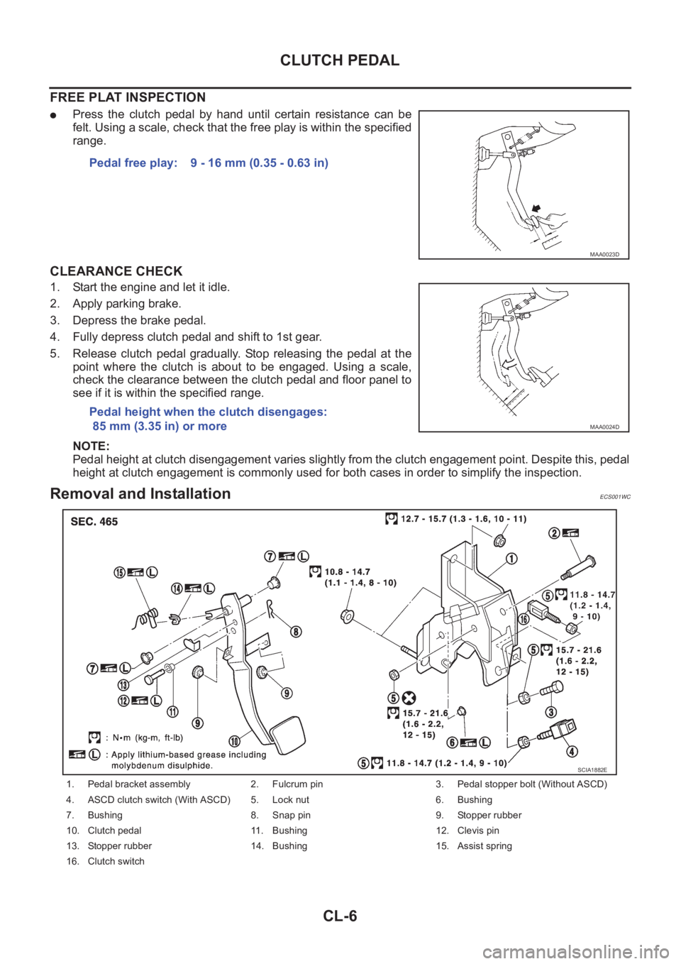
FREE PLAT INSPECTION
●Press the clutch pedal by hand until certain resistance can be
felt. Using a scale, check that the free play is within the specified
range.
CLEARANCE CHECK
1. Start the engine and let it idle.
2. Apply parking brake.
3. Depress the brake pedal.
4. Fully depress clutch pedal and shift to 1st gear.
5. Release clutch pedal gradually. Stop releasing the pedal at the
point where the clutch is about to be engaged. Using a scale,
check the clearance between the clutch pedal and floor panel to
see if it is within the specified range.
NOTE:
Pedal height at clutch disengagement varies slightly from the clutch engagement point. Despite this, pedal
height at clutch engagement is commonly used for both cases in order to simplify the inspection.
Removal and InstallationECS001WC
Pedal free play: 9 - 16 mm (0.35 - 0.63 in)
MAA0023D
Pedal height when the clutch disengages:
85 mm (3.35 in) or more
MAA0024D
1. Pedal bracket assembly 2. Fulcrum pin 3. Pedal stopper bolt (Without ASCD)
4. ASCD clutch switch (With ASCD) 5. Lock nut 6. Bushing
7. Bushing 8. Snap pin 9. Stopper rubber
10. Clutch pedal 11. Bushing 12. Clevis pin
13. Stopper rubber 14. Bushing 15. Assist spring
16. Clutch switch
SCIA1882E
Page 1974 of 3833

CL-16
CLUTCH DISC, CLUTCH COVER AND FLYWHEEL
INSPECTION AND ADJUSTMENT AFTER REMOVAL
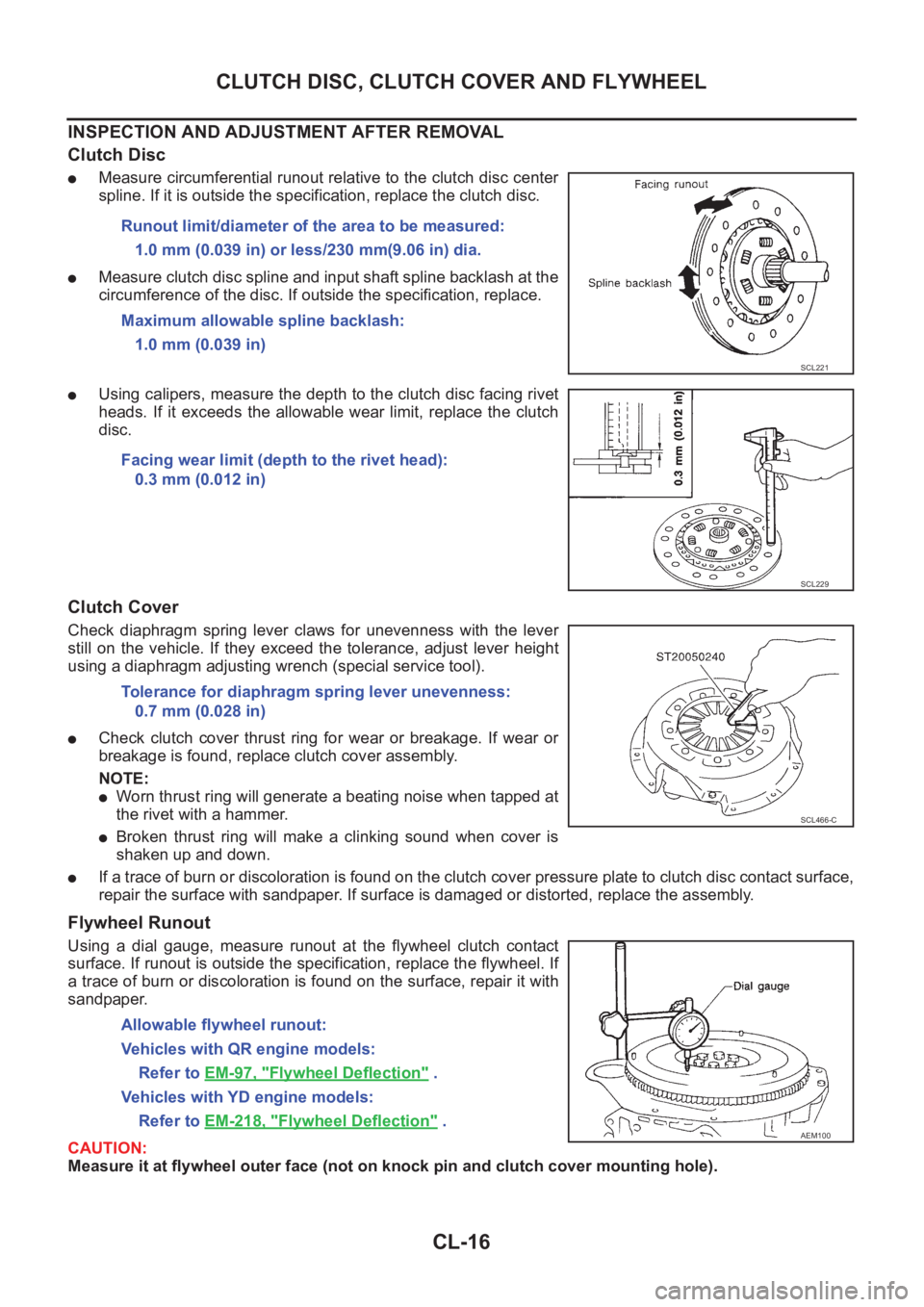
Clutch Disc
●Measure circumferential runout relative to the clutch disc center
spline. If it is outside the specification, replace the clutch disc.
●Measure clutch disc spline and input shaft spline backlash at the
circumference of the disc. If outside the specification, replace.
●Using calipers, measure the depth to the clutch disc facing rivet
heads. If it exceeds the allowable wear limit, replace the clutch
disc.
Clutch Cover
Check diaphragm spring lever claws for unevenness with the lever
still on the vehicle. If they exceed the tolerance, adjust lever height
using a diaphragm adjusting wrench (special service tool).
●Check clutch cover thrust ring for wear or breakage. If wear or
breakage is found, replace clutch cover assembly.
NOTE:
●Worn thrust ring will generate a beating noise when tapped at
the rivet with a hammer.
●Broken thrust ring will make a clinking sound when cover is
shaken up and down.
●If a trace of burn or discoloration is found on the clutch cover pressure plate to clutch disc contact surface,
repair the surface with sandpaper. If surface is damaged or distorted, replace the assembly.
Flywheel Runout
Using a dial gauge, measure runout at the flywheel clutch contact
surface. If runout is outside the specification, replace the flywheel. If
a trace of burn or discoloration is found on the surface, repair it with
sandpaper.
CAUTION:
Measure it at flywheel outer face (not on knock pin and clutch cover mounting hole). Runout limit/diameter of the area to be measured:
1.0 mm (0.039 in) or less/230 mm(9.06 in) dia.
Maximum allowable spline backlash:
1.0 mm (0.039 in)
SCL221
Facing wear limit (depth to the rivet head):
0.3 mm (0.012 in)
SCL229
Tolerance for diaphragm spring lever unevenness:
0.7 mm (0.028 in)
SCL466-C
Allowable flywheel runout:
Vehicles with QR engine models:
Refer to EM-97, "
Flywheel Deflection" .
Vehicles with YD engine models:
Refer to EM-218, "
Flywheel Deflection" .AEM100
Page 1986 of 3833

MT-10
M/T OIL
M/T OIL
PFP:KLD20
Changing M/T OilECS008BR
DRAINING
1. Start the engine and let it run to warm up the transaxle.
2. Stop the engine. Remove drain plug and drain oil.
3. Set a gasket on the drain plug and install it to the transaxle.
CAUTION:
Do not reuse gasket.
FILLING
1. Remove filler plug. Fill with new oil until oil level reaches the specified limit near filler plug mounting hole.
2. After refilling oil, check oil level. Assemble gasket to filler plug, then install it to transaxle body.
CAUTION:
Do not reuse gasket.
Checking M/T OilECS008BS
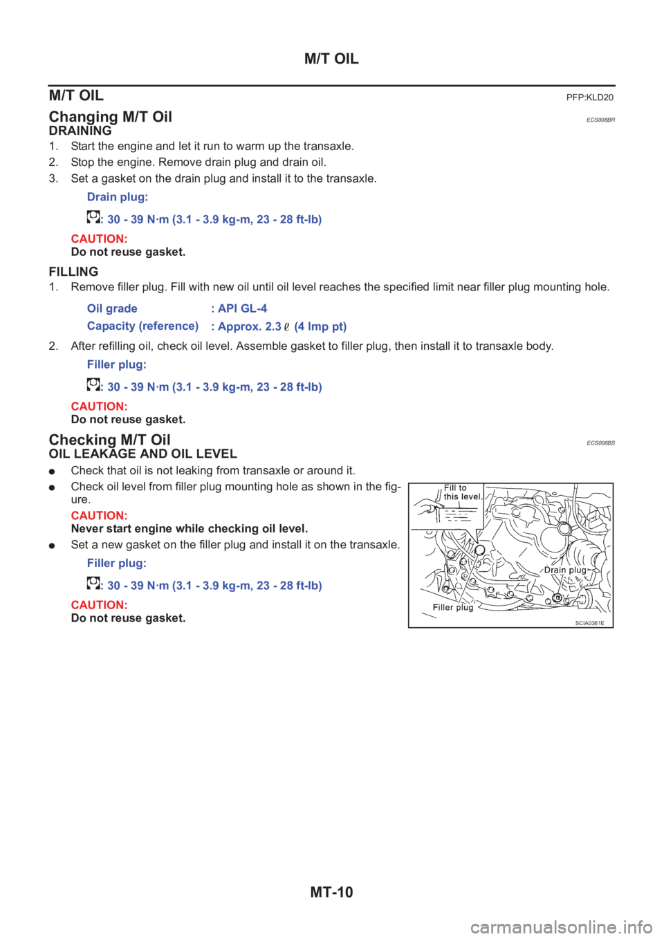
OIL LEAKAGE AND OIL LEVEL
●Check that oil is not leaking from transaxle or around it.
●Check oil level from filler plug mounting hole as shown in the fig-
ure.
CAUTION:
Never start engine while checking oil level.
●Set a new gasket on the filler plug and install it on the transaxle.
CAUTION:
Do not reuse gasket.Drain plug:
: 30 - 39 N·m (3.1 - 3.9 kg-m, 23 - 28 ft-lb)
Oil grade : API GL-4
Capacity (reference)
: Approx. 2.3 (4 lmp pt)
Filler plug:
: 30 - 39 N·m (3.1 - 3.9 kg-m, 23 - 28 ft-lb)
Filler plug:
: 30 - 39 N·m (3.1 - 3.9 kg-m, 23 - 28 ft-lb)
SCIA0361E
Page 1992 of 3833
MT-16
TRANSAXLE ASSEMBLY
15. Remove transaxle from vehicle.
INSTALLATION
Paying attention to the following items, install in the reverse order of removal.
●When installing the transaxle to the engine, tighten to the specified torque.
CAUTION:
When installing transaxle, be careful not to bring transaxle input shaft into contact with the clutch
cover.
QR engine models:
*: Tightening the bolt for 4WD models.
YD engine models:
●After installation, check oil level, and look for leaks and loose
mechanisms.
MTD0062D
Bolt No. 1 2 3* 4 5 6
Quantity 2 1 1 2 2 2
“ ” mm (in)40
(1.57)75
(2.95)45
(1.77)40
(1.57)30
(1.18)40
(1.57)
Tightening torque
N·m (kg - m, ft- lb)69.6 - 79.4
(7.1 - 8.1, 52 - 58)39.2 - 46.1
(4.0 - 4.7, 29 - 34)30.4 - 40.2
(3.1 - 4.1,
23 - 29)
Bolt No. 1 2 3 4 5 6
Quantity 2 2 1 1 3 1
“ ” mm (in)55
(2.17)70
(2.76)120
(4.72)45
(1.77)40
(1.57)35
(1.38)
Tightening torque
N·m (kg - m, ft- lb)40 - 49
(4.0 - 5.0, 29 - 36)31 - 36
(3.1 - 3.7, 23 - 26)
SCIA0353E
SCIA0748E