2001 NISSAN X-TRAIL oil
[x] Cancel search: oilPage 2768 of 3833
BR-28
REAR DISC BRAKE
Caliper Removal and Installation
EFS00180
REMOVAL
1. Connect a vinyl tube to the air bleeder.
2. Drain brake fluid gradually from air bleeder while depressing
brake pedal.
3. Remove brake hose connected to caliper assembly and union
bolts. Remove brake hose from caliper assembly.
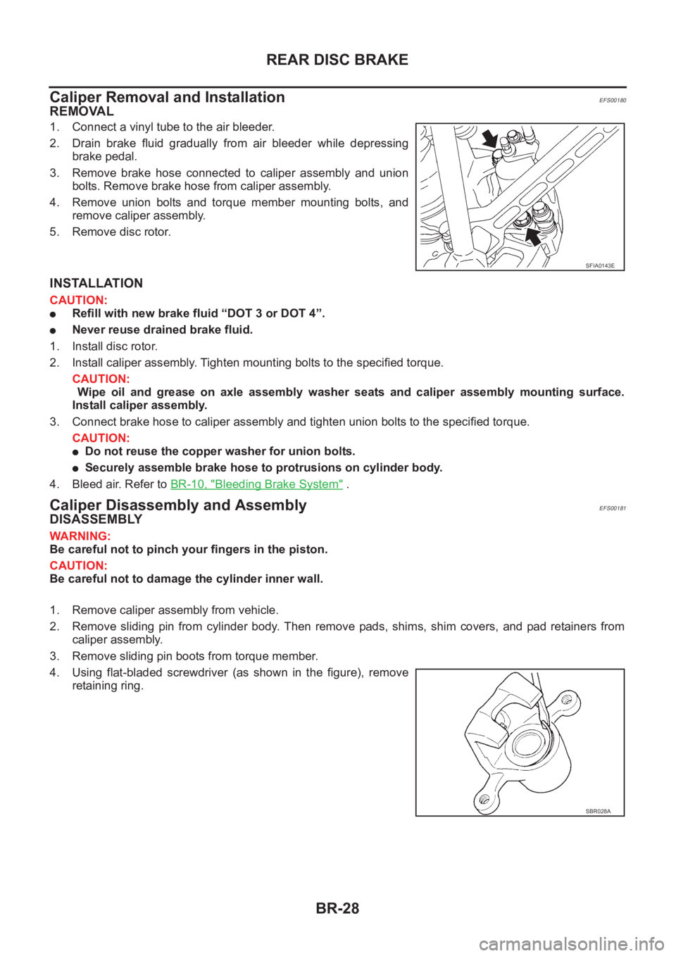
4. Remove union bolts and torque member mounting bolts, and
remove caliper assembly.
5. Remove disc rotor.
INSTALLATION
CAUTION:
●Refill with new brake fluid “DOT 3 or DOT 4”.
●Never reuse drained brake fluid.
1. Install disc rotor.
2. Install caliper assembly. Tighten mounting bolts to the specified torque.
CAUTION:
Wipe oil and grease on axle assembly washer seats and caliper assembly mounting surface.
Install caliper assembly.
3. Connect brake hose to caliper assembly and tighten union bolts to the specified torque.
CAUTION:
●Do not reuse the copper washer for union bolts.
●Securely assemble brake hose to protrusions on cylinder body.
4. Bleed air. Refer to BR-10, "
Bleeding Brake System" .
Caliper Disassembly and AssemblyEFS00181
DISASSEMBLY
WARNING:
Be careful not to pinch your fingers in the piston.
CAUTION:
Be careful not to damage the cylinder inner wall.
1. Remove caliper assembly from vehicle.
2. Remove sliding pin from cylinder body. Then remove pads, shims, shim covers, and pad retainers from
caliper assembly.
3. Remove sliding pin boots from torque member.
4. Using flat-bladed screwdriver (as shown in the figure), remove
retaining ring.
SFIA0143E
SBR028A
Page 2769 of 3833
REAR DISC BRAKE
BR-29
C
D
E
G
H
I
J
K
L
MA
B
BR
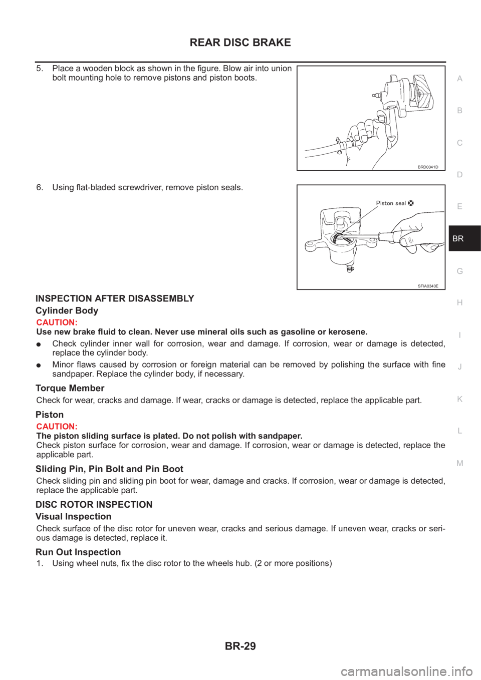
5. Place a wooden block as shown in the figure. Blow air into union
bolt mounting hole to remove pistons and piston boots.
6. Using flat-bladed screwdriver, remove piston seals.
INSPECTION AFTER DISASSEMBLY
Cylinder Body
CAUTION:
Use new brake fluid to clean. Never use mineral oils such as gasoline or kerosene.
●Check cylinder inner wall for corrosion, wear and damage. If corrosion, wear or damage is detected,
replace the cylinder body.
●Minor flaws caused by corrosion or foreign material can be removed by polishing the surface with fine
sandpaper. Replace the cylinder body, if necessary.
Torque Member
Check for wear, cracks and damage. If wear, cracks or damage is detected, replace the applicable part.
Piston
CAUTION:
The piston sliding surface is plated. Do not polish with sandpaper.
Check piston surface for corrosion, wear and damage. If corrosion, wear or damage is detected, replace the
applicable part.
Sliding Pin, Pin Bolt and Pin Boot
Check sliding pin and sliding pin boot for wear, damage and cracks. If corrosion, wear or damage is detected,
replace the applicable part.
DISC ROTOR INSPECTION
Visual Inspection
Check surface of the disc rotor for uneven wear, cracks and serious damage. If uneven wear, cracks or seri-
ous damage is detected, replace it.
Run Out Inspection
1. Using wheel nuts, fix the disc rotor to the wheels hub. (2 or more positions)
BRD0041D
SFIA0340E
Page 2771 of 3833
REAR DISC BRAKE
BR-31
C
D
E
G
H
I
J
K
L
MA
B
BR
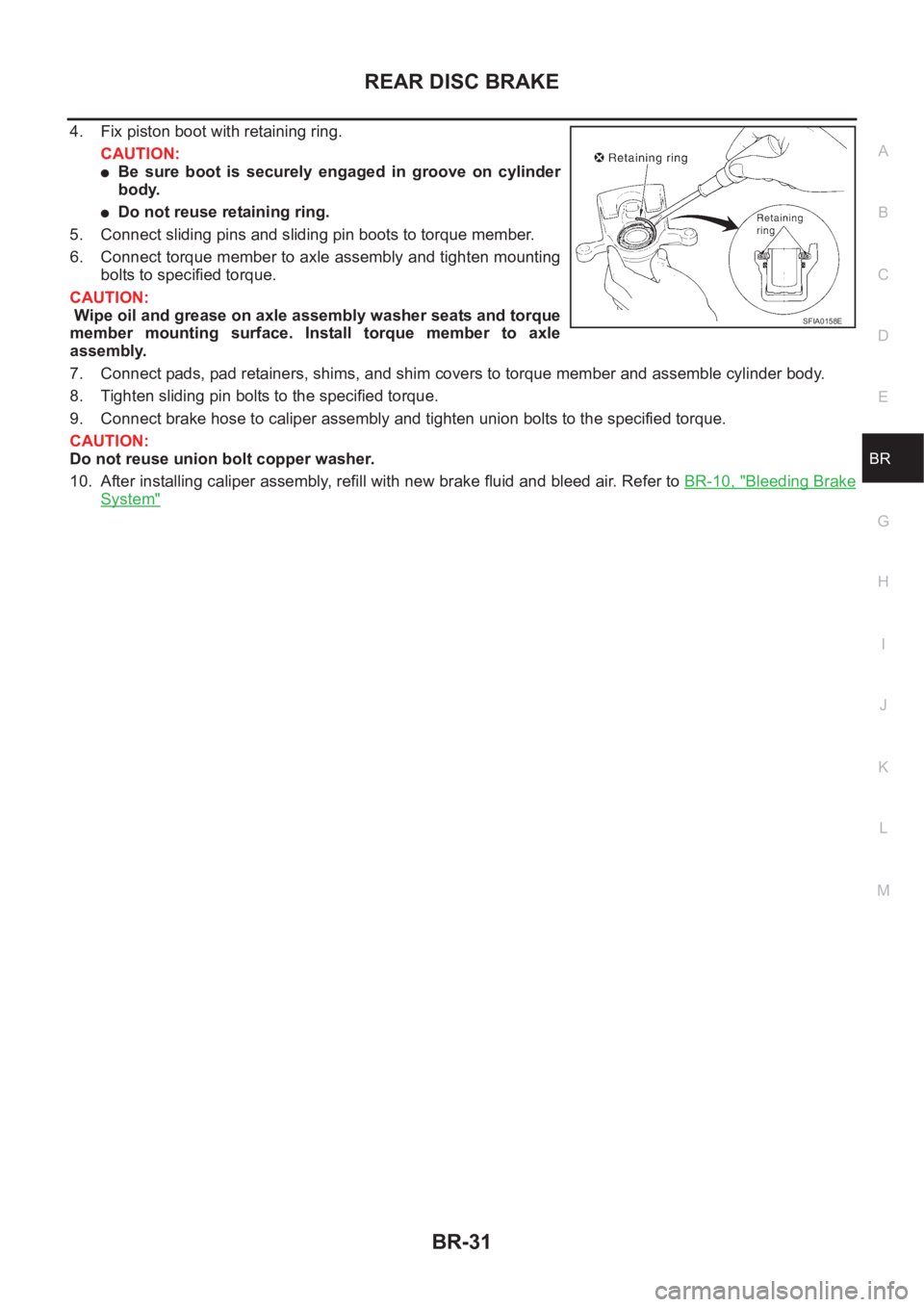
4. Fix piston boot with retaining ring.
CAUTION:
●Be sure boot is securely engaged in groove on cylinder
body.
●Do not reuse retaining ring.
5. Connect sliding pins and sliding pin boots to torque member.
6. Connect torque member to axle assembly and tighten mounting
bolts to specified torque.
CAUTION:
Wipe oil and grease on axle assembly washer seats and torque
member mounting surface. Install torque member to axle
assembly.
7. Connect pads, pad retainers, shims, and shim covers to torque member and assemble cylinder body.
8. Tighten sliding pin bolts to the specified torque.
9. Connect brake hose to caliper assembly and tighten union bolts to the specified torque.
CAUTION:
Do not reuse union bolt copper washer.
10. After installing caliper assembly, refill with new brake fluid and bleed air. Refer to BR-10, "
Bleeding Brake
System"
SFIA0158E
Page 2788 of 3833
![NISSAN X-TRAIL 2001 Service Repair Manual BRC-4
[4WD/ABS]
PRECAUTIONS
[4WD/ABS]PRECAUTIONSPFP:00001
Precautions for brake systemEFS001B6
●Recommended fluid is brake fluid “DOT 3 ”or “DOT 4”.
●Never reuse drained brake fluid.
●Be NISSAN X-TRAIL 2001 Service Repair Manual BRC-4
[4WD/ABS]
PRECAUTIONS
[4WD/ABS]PRECAUTIONSPFP:00001
Precautions for brake systemEFS001B6
●Recommended fluid is brake fluid “DOT 3 ”or “DOT 4”.
●Never reuse drained brake fluid.
●Be](/manual-img/5/57405/w960_57405-2787.png)
BRC-4
[4WD/ABS]
PRECAUTIONS
[4WD/ABS]PRECAUTIONSPFP:00001
Precautions for brake systemEFS001B6
●Recommended fluid is brake fluid “DOT 3 ”or “DOT 4”.
●Never reuse drained brake fluid.
●Be careful not to splash brake fluid on painted areas.
●To clean or wash all parts of master cylinder, disc brake caliper and wheel cylinder, use clean brake fluid.
●Never use mineral oils such as gasoline or kerosene. They will ruin rubber parts of the hydraulic system.
●Use flare nut wrench when removing and installing brake tube.
●Always torque brake lines when installing.
●Burnish the brake contact surfaces after refinishing or replacing
drums or rotors, after replacing pads or linings, or if a soft pedal
occurs at very low mileage. Refer to BR-10, "
Brake Burnishing
Procedure" .
●Before working, turn OFF ignition switch. Disconnect connectors
for ABS actuator and control module or battery terminals.
WARNING:
●Clean brake pads and shoes with a waste cloth, then wipe
with a dust collector.
Precautions for brake controlEFS001B7
●If malfunction is indicated by 4WD warning lamp and/or ABS warning lamp, collect necessary information
from customer (what symptoms are present under what conditions). Find out possible causes before start-
ing service. Besides electrical system inspection, check operation of ABS actuator.
●If malfunction is detected, proceed to trouble diagnosis after checking tire pressure and tire wear.
●Stopping distance or steering stability may be deteriorated by the following conditions. Tire size and type
are in improper combination. Brake pads are not Nissan genuine parts.
●Fitting tires of different size on vehicle can be cause of longitudinal vibration. Always use tires of the same
size and brand. Exchange front and rear tires on the following conditions: Longitudinal vibration occurs in
vehicle with tires of the same size and brand. After replacement, perform trouble diagnosis. 1580|None
●4WD/ABS function may have a failure or error under following condition: There is radio, antenna, or
antenna lead-in wire (including wiring) near control module.
●If aftermarket parts (e.g. Car stereo equipment, CD player) have been installed, check electrical har-
nesses for pinches, open, and improper wiring.
SBR820BA
Page 2838 of 3833
![NISSAN X-TRAIL 2001 Service Repair Manual BRC-54
[ESP/TCS/ABS]
PRECAUTIONS
[ESP/TCS/ABS]PRECAUTIONSPFP:00001
Precautions for Brake SystemEFS0019O
●Recommended fluid is brake fluid “DOT 3” or “DOT 4”.
●Never reuse drained brake flu NISSAN X-TRAIL 2001 Service Repair Manual BRC-54
[ESP/TCS/ABS]
PRECAUTIONS
[ESP/TCS/ABS]PRECAUTIONSPFP:00001
Precautions for Brake SystemEFS0019O
●Recommended fluid is brake fluid “DOT 3” or “DOT 4”.
●Never reuse drained brake flu](/manual-img/5/57405/w960_57405-2837.png)
BRC-54
[ESP/TCS/ABS]
PRECAUTIONS
[ESP/TCS/ABS]PRECAUTIONSPFP:00001
Precautions for Brake SystemEFS0019O
●Recommended fluid is brake fluid “DOT 3” or “DOT 4”.
●Never reuse drained brake fluid.
●Be careful not to splash brake fluid on painted areas; it may cause paint damage. If brake fluid is splashed
on painted areas, wash it away with water immediately.
●Never use mineral oils such as gasoline or kerosene. They will ruin rubber parts of hydraulic system.
●Use flare nut wrench when removing and installing brake tubes.
●Always torque brake lines when installing.
●Before working, turn the ignition switch OFF and disconnect the
connectors for the ESP/TCS/ABS actuator and control unit or
the battery terminals.
●Burnish the brake contact surfaces after refinishing or replacing
drums or rotors, after replacing pads or linings, or if a soft pedal
occurs at very low mileage. Refer to BR-10, "
Brake Burnishing
Procedure" .
WARNING:
Clean brakes with a vacuum dust collector to minimize risk
of health hazard from powder caused by friction.
Precautions for Brake ControlEFS0019P
●During the ESP/TCS/ABS operation, the brake pedal vibrates lightly and its mechanical noise may be
heard. This is a normal condition.
●Just after starting the vehicle after ignition switch ON, the brake pedal may vibrate or the motor operating
noise may be heard from the engine compartment. This is a normal status of the operation check.
●The stopping distance may be longer than that of vehicles without ABS when the vehicle drives on rough,
gravel, or snowy (fresh deep snow) road.
●If a malfunction is indicated by the ABS warning lamp, or other warning lamps, collect the necessary infor-
mation from the customer (what symptoms are present under what conditions) and find out the possible
causes before starting the service. Besides the electrical system inspection, check the booster operation,
brake fluid level, and oil leaks.
●If the tire size and type are used in a improper combination, or the brake pads are not NISSAN genuine
parts, the stopping distance or steering stability may deteriorate.
●If there is a radio, antenna, or antenna lead-in wire (including wiring) near the control unit, the ESP/TCS/
ABS function may have a malfunction or error.
●If aftermarket parts (e.g. Car stereo equipment, CD player) have been installed, check the electrical har-
nesses for pinches, open, and improper wiring.
Precautions for CAN SystemEFS001CP
FOR INSPECTION
●Do not apply voltage of 7.0V or higher to the measurement terminals.
●Use the tester with its open terminal voltage being 7.0V or less.
●Before harness inspection, turn the ignition switch off, disconnect the negative battery terminal.
SBR820BA
Page 2911 of 3833
PS-1
POWER STEERING SYSTEM
G STEERING
CONTENTS
C
D
E
F
H
I
J
K
L
M
SECTION
A
B
PS
POWER STEERING SYSTEM
PRECAUTIONS .......................................................... 2
Precautions for Supplemental Restraint System
(SRS) “AIR BAG” and “SEAT BELT PRE-TEN-
SIONER” .................................................................. 2
Caution ..................................................................... 2
PREPARATION ........................................................... 3
Special Service Tools ............................................... 3
NOISE, VIBRATION, AND HARSHNESS (NVH)
TROUBLESHOOTING ................................................ 4
NVH Trouble shooting Chart .................................... 4
POWER STEERING FLUID ........................................ 5
Checking Fluid Level ........................................... ..... 5
Checking Fluid Leak ............................................ ..... 5
Bleeding Hydraulic System ...................................... 5
STEERING WHEEL .................................................... 6
On-Vehicle Inspection and Service .......................... 6
PLAY INSPECTION .............................................. 6
NEUTRAL POSITION INSPECTION .................... 6
STEERING TORQUE CHECK .............................. 6
STEERING ANGLE INSPECTION ........................ 6
Removal and Installation .......................................... 7
REMOVAL ............................................................. 7
INSTALLATION ..................................................... 7
STEERING COLUMN ................................................. 9
Removal and Installation .......................................... 9
REMOVAL OF LOWER JOINT AND HOLE
COVER ................................................................. 9
INSTALLATION OF LOWER JOINT AND HOLE
COVER ................................................................. 9
REMOVAL OF STEERING COLUMN ASSEM-
BLY ...................................................................... 10
INSTALLING STEERING COLUMN ASSEMBLY ... 10
Disassembly and Assembly .................................... 11
DISASSEMBLY .................................................... 11
INSPECTION AFTER DISASSEMBLY. ............... 11
ASSEMBLY .......................................................... 11
POWER STEERING GEAR AND LINKAGE ............ 12
Removal and Installation ........................................ 12
REMOVAL ........................................................... 12INSTALLATION ................................................... 12
Components ........................................................... 14
MODEL PR24AD ................................................. 14
Disassembly and Assembly .................................... 15
DISASSEMBLY ................................................... 15
INSPECTION AFTER DISASSEMBLY ................ 16
ASSEMBLY ......................................................... 17
POWER STEERING OIL PUMP ............................... 24
On-Vehicle Inspection and Service ......................... 24
OIL PUMP PULLEY HYDRAULIC PRESSURE
INSPECTION ...................................................... 24
Removal and Installation (QR20DE and QR25DE
engine models) ....................................................... 24
REMOVAL ........................................................... 24
INSTALLATION ................................................... 24
Disassembly and Assembly(QR20DE and
QR25DE engine models) ........................................ 25
INSPECTION BEFORE DISASSEMBLY ............. 25
DISASSEMBLY ................................................... 25
INSPECTION AFTER DISASSEMBLY ................ 26
ASSEMBLY ......................................................... 26
Removal and Installation (YD22DDTi engine
model) ..................................................................... 29
Disassembly and Assembly (YD22DDTi engine
model) ..................................................................... 30
INSPECTION BEFORE DISASSEMBLY ............. 30
DISASSEMBLY ................................................... 31
INSPECTION AFTER DISASSEMBLY ................ 32
ASSEMBLY ......................................................... 32
HYDRAULIC LINE .................................................
... 34
Removal and Installation ........................................ 34
SERVICE DATA AND SPECIFICATIONS (SDS) ...... 36
Wheel ..................................................................... 36
Steering Angle ........................................................ 36
Steering Column ..................................................... 36
Steering Linkage ..................................................... 36
Steering Gear ......................................................... 37
Oil Pump ................................................................. 37
Steering Fluid .......................................................... 37
Page 2912 of 3833
PS-2
PRECAUTIONS
PRECAUTIONS
PFP:00001
Precautions for Supplemental Restraint System (SRS) “AIR BAG” and “SEAT
BELT PRE-TENSIONER”
EGS000IZ
The Supplemental Restraint System such as “AIR BAG” and “SEAT BELT PRE-TENSIONER”, used along
with a front seat belt, helps to reduce the risk or severity of injury to the driver and front passenger for certain
types of collision. Information necessary to service the system safely is included in the SRS and SB section of
this Service Manual.
WARNING:
●To avoid rendering the SRS inoperative, which could increase the risk of personal injury or death
in the event of a collision which would result in air bag inflation, all maintenance must be per-
formed by an authorized NISSAN/INFINITI dealer.
●Improper maintenance, including incorrect removal and installation of the SRS, can lead to per-
sonal injury caused by unintentional activation of the system. For removal of Spiral Cable and Air
Bag Module, see the SRS section.
●Do not use electrical test equipment on any circuit related to the SRS unless instructed to in this
Service Manual. SRS wiring harnesses can be identified by yellow and/or orange harness connec-
tors.
CautionEGS00049
●Always follow the warnings and the cautions below in disassembly procedures:
–Work in a clean, dust-free place. No dust proof device is necessary.
–Clean outside of unit before disassembly.
–Clean parts to be disassembled. Be careful not to allow any dirt or other foreign materials to enter or con-
tact with parts.
–Assemble disassembled parts properly, following order shown in manual. If work has been suspended in
the middle of assembly, place a clean cover over parts. This will prevent them from being contaminated.
–Use paper towels when removing dirt and other foreign materials. Cloth shop towels can leave lint on
cleaned parts that might affect operation of parts.
–Clean disassembled parts (except rubber parts) with kerosene. Drain oil by blowing with air or absorbing
with shop papers.
–Before assembling, apply Nissan power steering fluid to O-rings and seals.
–Replace gaskets and O-rings with new ones. Be careful not to damage any O-rings, oil seals, and gaskets
during assembly.
●If following part is scratched after disassembly of steering pump, replace applicable part: case, rear body,
side plate, pulley, rotor, vane, or flow control valve
●Mark source of fluid leak with a white marker for identification.
● Seals and copper washers must not be reused.
Page 2913 of 3833
PREPARATION
PS-3
C
D
E
F
H
I
J
K
L
MA
B
PS
PREPARATIONPFP:00002
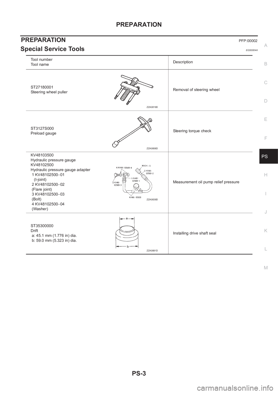
Special Service ToolsEGS0004A
Tool number
Tool nameDescription
ST27180001
Steering wheel pullerRemoval of steering wheel
ST3127S000
Preload gaugeSteering torque check
KV48103500
Hydraulic pressure gauge
KV48102500
Hydraulic pressure gauge adapter
1 KV48102500−01
(I-joint)
2 KV48102500−02
(Flare joint)
3 KV48102500−03
(Bolt)
4 KV48102500−04
(Washer)Measurement oil pump relief pressure
ST35300000
Drift
a: 45.1 mm (1.776 in) dia.
b: 59.0 mm (5.323 in) dia.Installing drive shaft seal
ZZA0819D
ZZA0806D
ZZA0839D
ZZA0881D