Page 2943 of 3833
POWER STEERING OIL PUMP
PS-33
C
D
E
F
H
I
J
K
L
MA
B
PS
4. Insert pin 2 into pin groove 1 of front housing and front side
plate. Then install cam ring 3 as shown at left.
Cam ring : D
1 is less than D2
SST472C
Page 2947 of 3833
SERVICE DATA AND SPECIFICATIONS (SDS)
PS-37
C
D
E
F
H
I
J
K
L
MA
B
PS
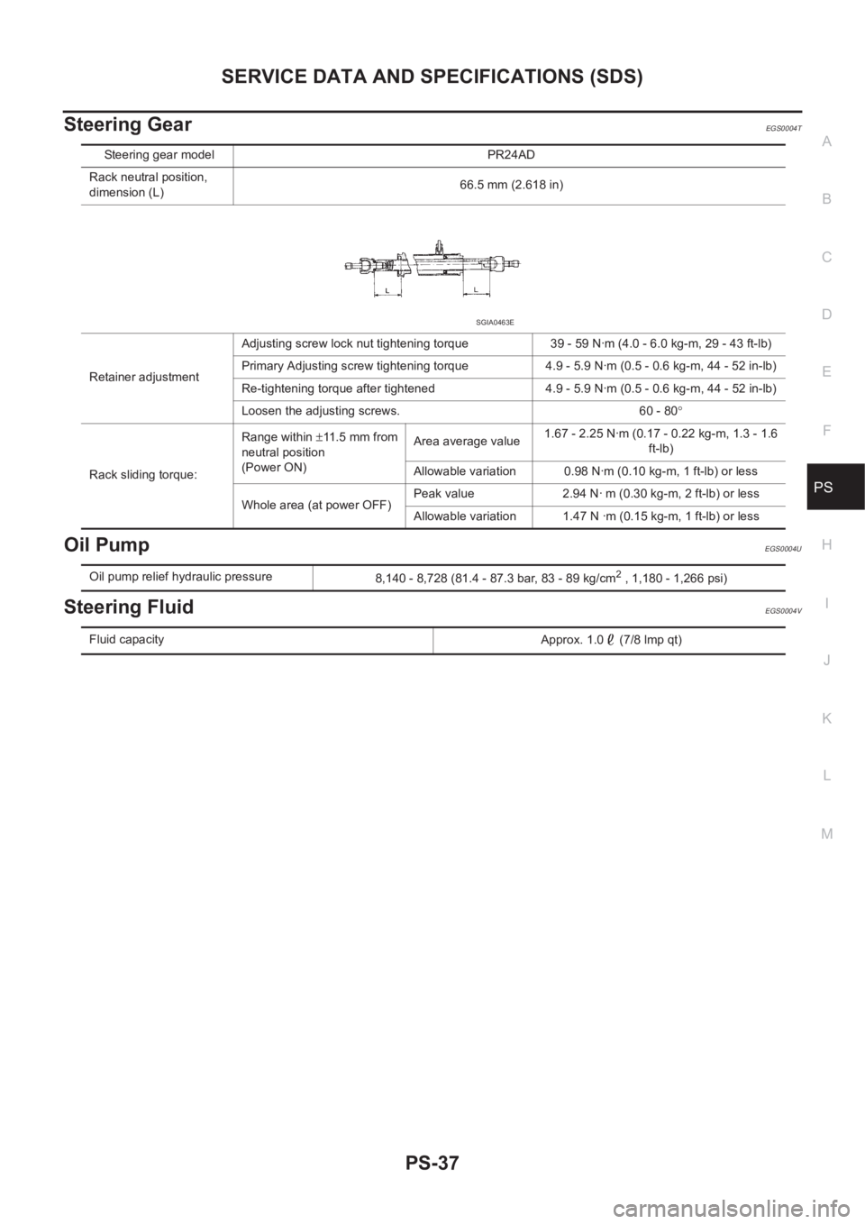
Steering GearEGS0004T
Oil PumpEGS0004U
Steering FluidEGS0004V
Steering gear model PR24AD
Rack neutral position,
dimension (L)66.5 mm (2.618 in)
Retainer adjustmentAdjusting screw lock nut tightening torque 39 - 59 N·m (4.0 - 6.0 kg-m, 29 - 43 ft-lb)
Primary Adjusting screw tightening torque 4.9 - 5.9 N·m (0.5 - 0.6 kg-m, 44 - 52 in-lb)
Re-tightening torque after tightened 4.9 - 5.9 N·m (0.5 - 0.6 kg-m, 44 - 52 in-lb)
Loosen the adjusting screws. 60 - 80°
Rack sliding torque:Range within ±11.5 mm from
neutral position
(Power ON)Area average value1.67 - 2.25 N·m (0.17 - 0.22 kg-m, 1.3 - 1.6
ft-lb)
Allowable variation 0.98 N·m (0.10 kg-m, 1 ft-lb) or less
Whole area (at power OFF)Peak value 2.94 N· m (0.30 kg-m, 2 ft-lb) or less
Allowable variation 1.47 N ·m (0.15 kg-m, 1 ft-lb) or less
SGIA0463E
Oil pump relief hydraulic pressure
8,140 - 8,728 (81.4 - 87.3 bar, 83 - 89 kg/cm2 , 1,180 - 1,266 psi)
Fluid capacity
Approx. 1.0 (7/8 lmp qt)
Page 2950 of 3833
FAX-2
PRECAUTIONS
PRECAUTIONS
PFP:00001
CautionEDS0005P
●When installing rubber parts, final tightening must be carried out under unladen condition* with tires on
ground.
●Oil will shorten the life of rubber bushes. Be sure to wipe off any spilled oil.
*: Fuel, radiator coolant and engine oil full. Spare tire, jack, hand tools and mats in designated positions.
●After installing removed suspension parts, check wheel alignment and adjust if necessary.
Observe the following precautions when disassembling and servicing drive shaft.
●Perform work in a location which is as dust-free and dirt-free as possible.
●Before disassembling and servicing, clean the outside of parts.
●Disassembly and service location must be taken to prevent the entry of foreign objects.
●Disassembled parts must be carefully reassembled in the correct order. If work is interrupted, a clean
cover must be placed over parts.
●Paper shop cloths must be used. Fabric shop cloths must not be used because of the danger of lint adher-
ing to parts.
●Disassembled parts (except for rubber parts) should be cleaned with kerosene which shall be removed by
blowing with air or wiping with paper shop cloths.
Page 2960 of 3833
FAX-12
FRONT DRIVE SHAFT
●When the drive shafts listed below have been removed, check that a circular clip is attached to the end.
×: Applicable
–: Not applicable
●Remove installation bolt from right-side drive shaft support bearing bracket. Then remove bracket from
engine.
●Remove installation bolt from right-side drive shaft and remove drive shaft from side shaft.
INSPECTION AFTER REMOVAL
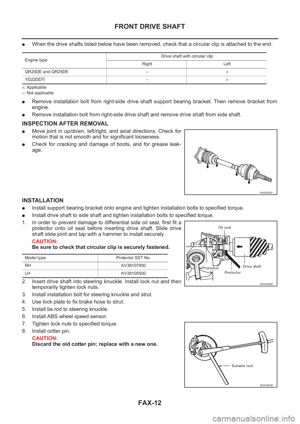
●Move joint in up/down, left/right, and axial directions. Check for
motion that is not smooth and for significant looseness.
●Check for cracking and damage of boots, and for grease leak-
age.
INSTALLATION
●Install support bearing bracket onto engine and tighten installation bolts to specified torque.
●Install drive shaft to side shaft and tighten installation bolts to specified torque.
1. In order to prevent damage to differential side oil seal, first fit a
protector onto oil seal before inserting drive shaft. Slide drive
shaft slide joint and tap with a hammer to install securely.
CAUTION:
Be sure to check that circular clip is securely fastened.
2. Insert drive shaft into steering knuckle. Install lock nut and then
temporarily tighten lock nuts.
3. Install installation bolt for steering knuckle and strut.
4. Use lock plate to fix brake hose to strut.
5. Install tie rod to steering knuckle.
6. Install ABS wheel speed sensor.
7. Tighten lock nuts to specified torque.
8. Install cotter pin.
CAUTION:
Discard the old cotter pin; replace with a new one.
Engine typeDrive shaft with circular clip
Right Left
QR20DE and QR25DE –×
YD22DDTi –×
RAA0030D
Model type Protector SST No.
RH KV38107800
LH KV38105500
SDIA0593E
SDIA0603E
Page 2968 of 3833
RAX-2
PRECAUTIONS
PRECAUTIONS
PFP:00001
CautionEDS00060
●When installing rubber parts, final tightening must be carried out under unladen condition* with tires on
ground.
*: Fuel, radiator coolant and engine oil full. Spare tire, jack, hand tools and mats in designated positions.
●After installing removed suspension parts, check wheel alignment and adjust if necessary.
Observe the following precautions when disassembling and servicing drive shaft.
●Perform work in a location which is as dust-free and dirt-free as possible.
●Before disassembling and servicing, clean the outside of parts.
●The disassembly and service location must be clean. Care must be taken to prevent parts from becoming
dirty and to prevent the entry of foreign objects.
●Disassembled parts must be carefully reassembled in the correct order. If work is interrupted, a clean
cover must be placed over parts.
●Paper shop cloths must be used. Fabric shop cloths must not be used because of the danger of lint adher-
ing to parts.
●Disassembled parts (except for rubber parts) should be cleaned with kerosene which shall be removed by
blowing with air or wiping with paper shop cloths.
Page 2975 of 3833
REAR DRIVE SHAFT
RAX-9
C
E
F
G
H
I
J
K
L
MA
B
RAX
REAR DRIVE SHAFTPFP:39600
Removal and InstallationEDS000FL
REMOVAL
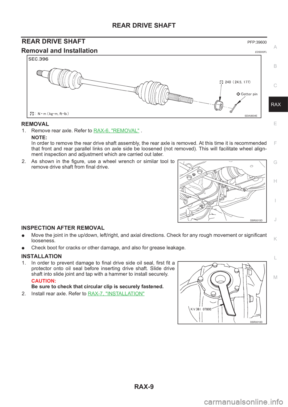
1. Remove rear axle. Refer to RAX-6, "REMOVAL" .
NOTE:
In order to remove the rear drive shaft assembly, the rear axle is removed. At this time it is recommended
that front and rear parallel links on axle side be loosened (not removed). This will facilitate wheel align-
ment inspection and adjustment which are carried out later.
2. As shown in the figure, use a wheel wrench or similar tool to
remove drive shaft from final drive.
INSPECTION AFTER REMOVAL
●Move the joint in the up/down, left/right, and axial directions. Check for any rough movement or significant
looseness.
●Check boot for cracks or other damage, and also for grease leakage.
INSTALLATION
1. In order to prevent damage to final drive side oil seal, first fit a
protector onto oil seal before inserting drive shaft. Slide drive
shaft into slide joint and tap with a hammer to install securely.
CAUTION:
Be sure to check that circular clip is securely fastened.
2. Install rear axle. Refer to RAX-7, "
INSTALLATION"
SDIA0604E
DSR0015D
DSR0010D
Page 2984 of 3833
SB-2
PRECAUTIONS
PRECAUTIONS
PFP:00001
Precautions for Supplemental Restraint System (SRS) “AIR BAG” and “SEAT
BELT PRE-TENSIONER”
EHS000MW
The Supplemental Restraint System such as “AIR BAG” and “SEAT BELT PRE-TENSIONER”, used along
with a front seat belt, helps to reduce the risk or severity of injury to the driver and front passenger for certain
types of collision. Information necessary to service the system safely is included in the SRS and SB section of
this Service Manual.
WARNING:
●To avoid rendering the SRS inoperative, which could increase the risk of personal injury or death
in the event of a collision which would result in air bag inflation, all maintenance must be per-
formed by an authorized NISSAN/INFINITI dealer.
●Improper maintenance, including incorrect removal and installation of the SRS, can lead to per-
sonal injury caused by unintentional activation of the system. For removal of Spiral Cable and Air
Bag Module, see the SRS section.
●Do not use electrical test equipment on any circuit related to the SRS unless instructed to in this
Service Manual. SRS wiring harnesses can be identified by yellow and/or orange harness connec-
tors.
Precaution for Seat Belt ServiceEHS000BE
CAUTION:
●Before removing the seat belt pre-tensioner assembly, turn the ignition switch off, disconnect
both battery cables and wait at least 3 minutes.
●Do not use electrical test equipment for seat belt pre-tensioner connector.
●After replacing or reinstalling seat belt pre-tensioner assembly, or reconnecting seat belt pre-ten-
sioner connector, check the system function. Refer to SRS-16, "
SRS Operation Check" .
●Do not use disassemble buckle or seat belt assembly.
●Replace anchor bolts if they are deformed or worn out.
●Never oil tongue and buckle.
●If any component of seat belt assembly is questionable, do not repair. Replace the whole seat belt
assembly.
●If webbing is cut, frayed, or damaged, replace seat belt assembly.
●When replacing seat belt assembly, use a genuine seat belt assembly.
AFTER A COLLISION
WARNING:
Inspect all seat belt assemblies including retractors and attaching hardware after any collision.
NISSAN recommends that all seat belt assemblies in use during a collision be replaced unless the col-
lision was minor and the belts show no damage and continue to operate properly. Failure to do so
could result in serious personal injury in an accident. Seat belt assemblies not in use during a colli-
sion should also be replaced if either damage or improper operation is noted. Seat belt pre-tensioner
should be replaced even if the seat belts are not in use during a frontal collision in which the air bags
are deployed.
Replace any seat belt assembly (including anchor bolts) if:
●The seat belt was in use at the time of a collision (except for minor collisions and the belts, retractors and
buckles show no damage and continue to operate properly).
●The seat belt was damaged in an accident. (i.e. torn webbing, bent retractor or guide, etc.)
●The seat belt attaching point was damaged in an accident. Inspect the seat belt attaching area for damage
or distortion and repair as necessary before installing a new seat belt assembly.
●Anchor bolts are deformed or worn out.
●The seat belt pre-tensioner should be replaced even if the seat belts are not in use during the collision in
which the air bags are deployed.
Page 3032 of 3833
SRS-30
DRIVER AIR BAG MODULE
CAUTION:
●Always work from the side of driver air bag module.
●Always place driver air bag module with pad side facing
upward.
●Do not insert any foreign objects (screwdriver, etc.) into
driver air bag module.
●Do not attempt to disassemble driver air bag module.
●Do not use old bolts after removal; replace with new bolts.
●Do not expose the driver air bag module to temperatures
exceeding 90°C(194°F).
●Replace air bag module if it has been dropped or sustained
an impact.
●Do not allow oil, grease or water to come in contact with the
front passenger air bag module.
INSTALLATION
To install, reverse the removal procedure sequence.
●After installing the air bag module, check that the contact clear-
ance of the horn switch is in the specified range in the right.
●For installing the air bag module, tighten the special bolts with
the center of the horn pad pressed to make the contacts (RH/
LH) ON.
SRS443
SBF814E
SHIA0185E
SHIA0184E