2001 NISSAN X-TRAIL oil
[x] Cancel search: oilPage 2715 of 3833
COIL SPRING AND SHOCK ABSORBER
FSU-9
C
D
F
G
H
I
J
K
L
MA
B
FSU
Insulator and Rubber Parts
Check strut mount insulator for cracks and rubber parts for wear. Replace them if necessary.
Coil Spring
Check for cracks, wear, and damage, and replace if necessary.
ASSEMBLY
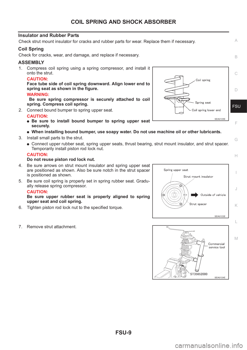
1. Compress coil spring using a spring compressor, and install it
onto the strut.
CAUTION:
Face tube side of coil spring downward. Align lower end to
spring seat as shown in the figure.
WARNING:
Be sure spring compressor is securely attached to coil
spring. Compress coil spring.
2. Connect bound bumper to spring upper seat.
CAUTION:
●Be sure to install bound bumper to spring upper seat
securely.
●When installing bound bumper, use soapy water. Do not use machine oil or other lubricants.
3. Install small parts to the strut.
●Connect upper rubber seat, spring upper seats, thrust bearing, strut mount insulator, and strut spacer.
Temporarily install piston rod lock nut.
CAUTION:
Do not reuse piston rod lock nut.
4. Be sure arrows on strut mount insulator and spring upper seat
are positioned as shown. Also be sure notch in the strut spacer
is positioned as shown.
5. Be sure coil spring is properly set in spring rubber seat. Gradu-
ally release spring compressor.
CAUTION:
Be sure upper rubber seat is properly aligned to spring
upper seat and coil spring.
6. Tighten piston rod lock nut to the specified torque.
7. Remove strut attachment.
SEIA0125E
SEIA0123E
SEIA0124E
Page 2719 of 3833
SERVICE DATA AND SPECIFICATIONS (SDS)
FSU-13
C
D
F
G
H
I
J
K
L
MA
B
FSU
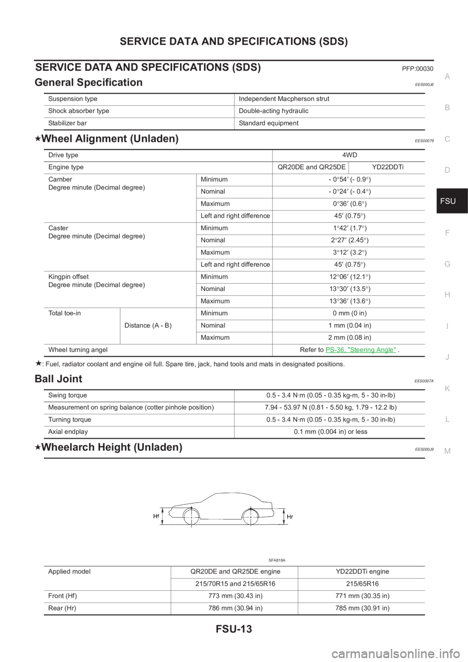
SERVICE DATA AND SPECIFICATIONS (SDS)PFP:00030
General SpecificationEES000J6
Wheel Alignment (Unladen)EES00079
: Fuel, radiator coolant and engine oil full. Spare tire, jack, hand tools and mats in designated positions.
Ball JointEES0007A
Wheelarch Height (Unladen)EES000J9
Suspension type Independent Macpherson strut
Shock absorber type Double-acting hydraulic
Stabilizer bar Standard equipment
Drive type4WD
Engine type QR20DE and QR25DE YD22DDTi
Camber
Degree minute (Decimal degree)Minimum - 0°54′ (- 0.9°)
Nominal - 0°24′ (- 0.4°)
Maximum 0°36′ (0.6°)
Left and right difference 45′ (0.75°)
Caster
Degree minute (Decimal degree)Minimum 1°42′ (1.7°)
Nominal 2°27′ (2.45°)
Maximum 3°12′ (3.2°)
Left and right difference 45′ (0.75°)
Kingpin offset
Degree minute (Decimal degree)Minimum 12°06′ (12.1°)
Nominal 13°30′ (13.5°)
Maximum 13°36′ (13.6°)
Total toe-in
Distance (A - B)Minimum 0 mm (0 in)
Nominal 1 mm (0.04 in)
Maximum 2 mm (0.08 in)
Wheel turning angel Refer to PS-36, "
Steering Angle" .
Swing torque 0.5 - 3.4 N·m (0.05 - 0.35 kg-m, 5 - 30 in-lb)
Measurement on spring balance (cotter pinhole position) 7.94 - 53.97 N (0.81 - 5.50 kg, 1.79 - 12.2 lb)
Turning torque 0.5 - 3.4 N·m (0.05 - 0.35 kg-m, 5 - 30 in-lb)
Axial endplay 0.1 mm (0.004 in) or less
Applied model QR20DE and QR25DE engine YD22DDTi engine
215/70R15 and 215/65R16 215/65R16
Front (Hf) 773 mm (30.43 in) 771 mm (30.35 in)
Rear (Hr) 786 mm (30.94 in) 785 mm (30.91 in)
SFA818A
Page 2720 of 3833
FSU-14
SERVICE DATA AND SPECIFICATIONS (SDS)
: Fuel, radiator coolant and engine oil full. Spare tire, jack, hand tools and mats in designated positions.
Page 2721 of 3833
RSU-1
REAR SUSPENSION
E SUSPENSION
CONTENTS
C
D
F
G
H
I
J
K
L
M
SECTION
A
B
RSU
REAR SUSPENSION
PRECAUTIONS .......................................................... 2
Caution ..................................................................... 2
PREPARATION ........................................................... 3
Special Service Tool ................................................. 3
Commercial Service Tools ........................................ 3
NOISE, VIBRATION, AND HARSHNESS (NVH)
TROUBLESHOOTING ................................................ 4
NVH Troubleshooting Chart ..................................... 4
REAR SUSPENSION ASSEMBLY ............................. 5
Components ............................................................. 5
On-Vehicle Inspection and Service .......................... 6
Wheel Alignment ...................................................... 6
DESCRIPTION ...................................................... 6
PRELIMINARY INSPECTION ............................... 6
CAMBER ............................................................... 6
TOE-IN .................................................................. 6
COIL SPRING AND STRUT ....................................... 8
Removal and Installation .......................................... 8
REMOVAL ............................................................. 8
INSTALLATION ..................................................... 8
Disassembly and Assembly ..................................... 8
DISASSEMBLY ..................................................... 8
INSPECTION AFTER DISASSEMBLY ................. 8
ASSEMBLY ........................................................... 9FRONT PARALLEL LINK ......................................... 10
Removal and Installation ........................................ 10
REMOVAL ........................................................... 10
INSPECTION AFTER REMOVAL ....................... 10
INSTALLATION ................................................... 10
REAR PARALLEL LINK ........................................... 11
Removal and Installation ........................................ 11
REMOVAL ........................................................... 11
INSPECTION AFTER REMOVAL ....................... 11
INSTALLATION ................................................... 11
RADIUS ROD ............................................................ 12
Removal and Installation ........................................ 12
REMOVAL ........................................................... 12
INSPECTION AFTER REMOVAL ....................... 12
INSTALLATION ................................................... 12
REAR SUSPENSION MEMBER ............................... 13
Removal and Installation ........................................ 13
REMOVAL ........................................................... 13
INSTALLATION ................................................... 13
SERVICE DATA AND SPECIFICATIONS (SDS) ...... 14
General Specification .........................................
.... 14
Wheel Alignment (Unladen) .................................... 14
Wheelarch Height (Unladen) .................................. 14
Page 2722 of 3833
RSU-2
PRECAUTIONS
PRECAUTIONS
PFP:00001
CautionEES0007C
● Final tightening of bushings must be carried out under unladen condition with tires on the ground. Oil will
shorten life of bushings. Be sure to wipe off any spilled oil.
●“Unladen condition” means that fuel, coolant and lubricant are full and ready for drive. However, spare tire,
jack, and hand tools should be unloaded.
●After installing the removed suspension parts, always check wheel alignment and adjust if necessary.
●Replace the caulking nut with a new one. Install a new nut without wiping the oil off before tightening.
Page 2723 of 3833
PREPARATION
RSU-3
C
D
F
G
H
I
J
K
L
MA
B
RSU
PREPARATIONPFP:00002
Special Service ToolEES0007D
Commercial Service ToolsEES000JD
Tool number
Tool nameDescription
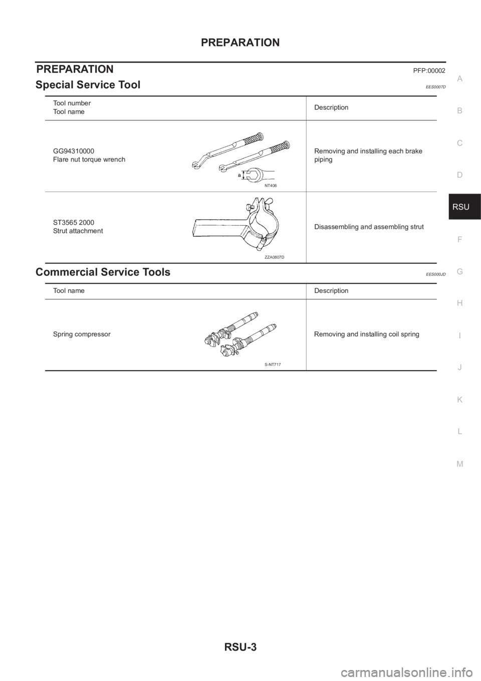
GG94310000
Flare nut torque wrenchRemoving and installing each brake
piping
ST3565 2000
Strut attachmentDisassembling and assembling strut
NT406
ZZA0807D
Tool nameDescription
Spring compressor Removing and installing coil spring
S-NT717
Page 2726 of 3833
RSU-6
REAR SUSPENSION ASSEMBLY
On-Vehicle Inspection and Service
EES0007F
Check axle and suspension parts for excessive play, wear, and damage.
●Move rear wheels (RH/LH) to check abnormal free play.
●Retighten all nuts and bolts to the specified torque.
●Check strut for oil leakage and damage.
Wheel AlignmentEES0007G
DESCRIPTION
●Measure wheel alignment under unladen conditions. “Unladen conditions” means that fuel, coolant, and
lubricant are full. However, spare tire, jack, and hand tools should be unloaded.
PRELIMINARY INSPECTION
1. Check the tires for improper air pressure and wear.
2. Check road wheels for runout.
3. Check wheel bearing axial endplay.
4. Check strut operation.
5. Check each mounting point of axle and suspension for looseness and deformation.
6. Check each link and arm for cracks, deformation, and other damage.
7. Check the vehicle posture.
CAMBER
Camber is preset at factory and cannot be adjusted.
●If the camber is not within specification, inspect and replace any damaged or worn rear suspension parts.
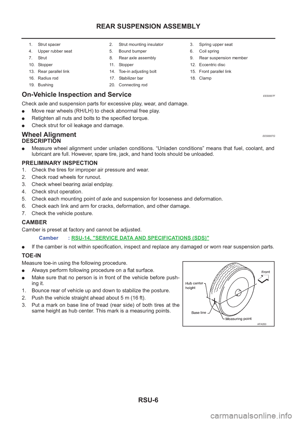
TOE-IN
Measure toe-in using the following procedure.
●Always perform following procedure on a flat surface.
●Make sure that no person is in front of the vehicle before push-
ing it.
1. Bounce rear of vehicle up and down to stabilize the posture.
2. Push the vehicle straight ahead about 5 m (16 ft).
3. Put a mark on base line of tread (rear side) of both tires at the
same height as hub center. This mark is a measuring points.
1. Strut spacer 2. Strut mounting insulator 3. Spring upper seat
4. Upper rubber seat 5. Bound bumper 6. Coil spring
7. Strut 8. Rear axle assembly 9. Rear suspension member
10. Stopper 11. Stopper 12. Eccentric disc
13. Rear parallel link 14. Toe-in adjusting bolt 15. Front parallel link
16. Radius rod 17. Stabilizer bar 18. Clamp
19. Bushing 20. Connecting rod
Camber : RSU-14, "SERVICE DATA AND SPECIFICATIONS (SDS)"
AFA050
Page 2728 of 3833
RSU-8
COIL SPRING AND STRUT
COIL SPRING AND STRUT
PFP:55302
Removal and InstallationEES0007H
REMOVAL
1. Remove tires.
2. Remove brake hose lock plate and remove brake hose from strut.
3. Remove mounting nuts and washers on upper portion of stabilizer connecting rod.
4. Remove strut-to-axle housing mounting bolts and nuts.
5. Remove luggage side lower finisher in luggage compartment. Remove mounting nuts on strut spacer.
Then remove strut from vehicle.
INSTALLATION
●Refer to RSU-5, "Components" for tightening torque. Install in the reverse order of removal.
Disassembly and AssemblyEES0007I
DISASSEMBLY
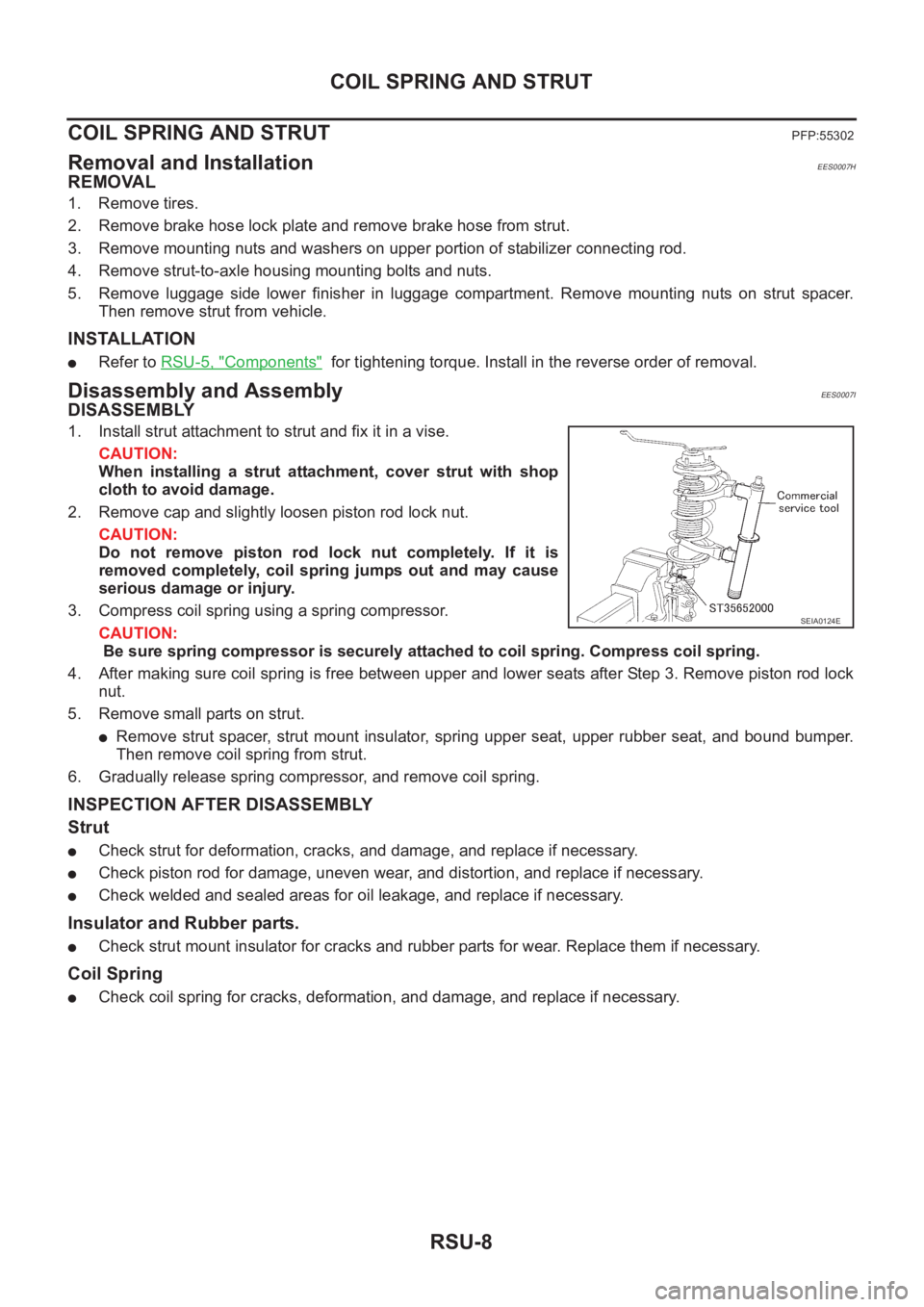
1. Install strut attachment to strut and fix it in a vise.
CAUTION:
When installing a strut attachment, cover strut with shop
cloth to avoid damage.
2. Remove cap and slightly loosen piston rod lock nut.
CAUTION:
Do not remove piston rod lock nut completely. If it is
removed completely, coil spring jumps out and may cause
serious damage or injury.
3. Compress coil spring using a spring compressor.
CAUTION:
Be sure spring compressor is securely attached to coil spring. Compress coil spring.
4. After making sure coil spring is free between upper and lower seats after Step 3. Remove piston rod lock
nut.
5. Remove small parts on strut.
●Remove strut spacer, strut mount insulator, spring upper seat, upper rubber seat, and bound bumper.
Then remove coil spring from strut.
6. Gradually release spring compressor, and remove coil spring.
INSPECTION AFTER DISASSEMBLY
Strut
●Check strut for deformation, cracks, and damage, and replace if necessary.
●Check piston rod for damage, uneven wear, and distortion, and replace if necessary.
●Check welded and sealed areas for oil leakage, and replace if necessary.
Insulator and Rubber parts.
●Check strut mount insulator for cracks and rubber parts for wear. Replace them if necessary.
Coil Spring
●Check coil spring for cracks, deformation, and damage, and replace if necessary.
SEIA0124E