Page 2678 of 3833

RFD-2
PRECAUTIONS
PRECAUTIONS
PFP:00001
CautionEDS00101
●Before starting diagnosis of the vehicle, understand symptoms well. Perform correct and systematic oper-
ations.
●Check for the correct installation status prior to removal or disassembly. When mating marks are required,
be sure they do not interfere with the function of the parts they are applied to.
●Carry out an overhaul in a clean work place. Using a dust proof room is recommended.
●Before disassembly, using steam or white gasoline, completely remove sand and mud from the exterior of
the unit, preventing them from entering into the unit during disassembly or assembly.
●Check appearance of the disassembled parts for damage, deformation, and abnormal wear. If a malfunc-
tion is detected, replace it with a new one.
●Normally replace lock pins, oil seals, and bearings with new ones every time they are removed.
●In principle, tighten bolts or nuts gradually in several steps working diagonally from inside to outside. If
tightening sequence is specified, observe it.
●Clean and flush the parts sufficiently and blow them dry.
●Be careful not to damage the sliding surfaces and mating surfaces.
●When applying sealant, remove the old sealant from the mounting surface; then remove any moisture, oil,
and foreign materials from the application and mounting surfaces.
●Always use shop paper for cleaning the inside of components.
●Avoid using cotton gloves or a shop cloth to prevent entering of lint.
●During assembly, observe the specified tightening torque, and apply new differential oil, Vaseline, or Nis-
san MP Special Grease No. 2, as specified for each vehicle, when necessary.
●Do not reuse drained oil. Discard waste oil after oil changes or part treatment in accordance with local
laws and regulations.
Precautions for Brake SystemEDS00102
●When installing rubber parts, final tightening must be carried out under unladen condition* with tires on
ground.
*: Fuel, radiator coolant and engine oil full. Spare tire, jack, hand tools and mats in designated positions.
●After installing removed suspension parts, check wheel alignment and adjust if necessary.
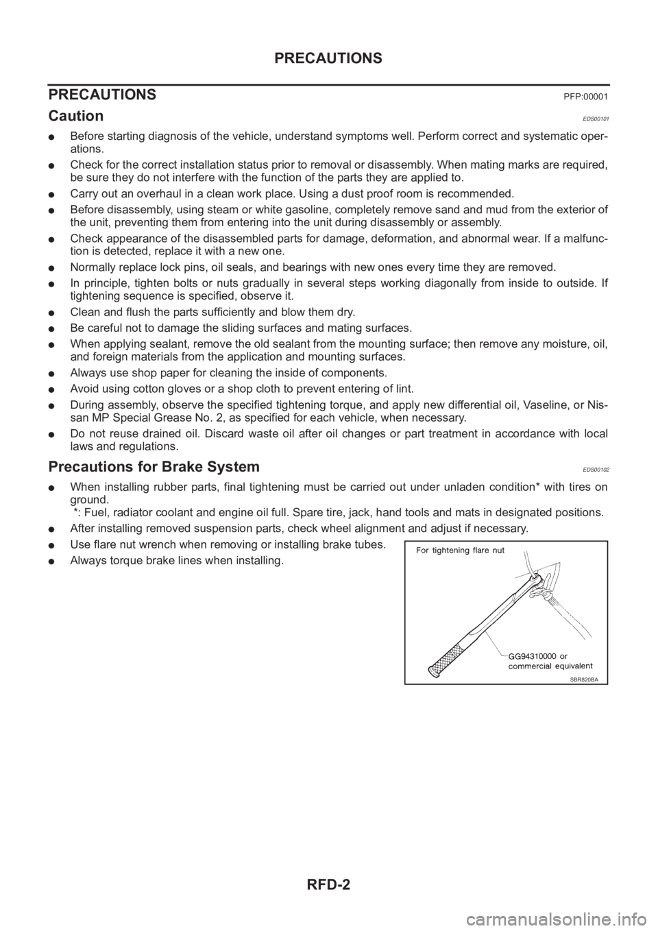
●Use flare nut wrench when removing or installing brake tubes.
●Always torque brake lines when installing.
SBR820BA
Page 2679 of 3833
PREPARATION
RFD-3
C
E
F
G
H
I
J
K
L
MA
B
RFD
PREPARATIONPFP:00002
Special Service ToolsEDS00103
Tool name
Tool numberDescription
Drift
ST27861000
a: 62 mm (2.44 in) dia.
b: 52 mm (2.05 in) dia.Installing final drive front oil seal
Drift
KV38100200
a: 65 mm (2.56 in) dia.
b: 49 mm (1.93 in) dia.
●Installing final drive front oil seal
●Installing final drive side oil seal
Preload gauge
ST3127S000Measuring preload torque
Drift
ST33052000
a: 22 mm (0.87 in) dia.
b: 28 mm (1.10 in) dia.
●Removing side bearing inner
Drift
KV40100610
a: 63 mm (2.48 in) dia.
b: 54.3 mm (2.138 in) dia.
●Removing and installing carrier
case and rear cover (2 pieces are
used)
●Installing pinion front bearing inner
race
Pin punch
ST23550000
Tip diameter: 4.5 mm (0.177 in) dia.Removing and installing lock pin
Drift
ST17130000
a: 31.8 mm (1.252 in) dia.
b: 58 mm (2.28 in) dia.Installing pinion rear bearing outer
race
ZZA0832D
ZZA1143D
ZZA0503D
ZZA1023D
ZZA0810D
ZZA0815D
ZZA0836D
Page 2680 of 3833
RFD-4
PREPARATION
Drift
ST33230000
a: 51 mm (2.01 in) dia.
b: 41 mm (1.61 in) dia.
c: 28.5 mm (1.122 in) dia.Installing pinion front bearing outer
race
Drift
ST23860000
a: 38 mm (1.50 in) dia.
b: 33 mm (1.30 in) dia.
●Installing pinion rear bearing inner
race
●Installing pinion front bearing inner
race
Press stand
ST38220000
a: 63 mm (2.48 in) dia.
b: 65 mm (2.56 in)Installing pinion front bearing inner
race
Drift
KV40105020
a: 39.7 mm (1.563 in) dia.
b: 35 mm (1.38 in) dia.
c: 15 mm (0.59 in)Installing side bearing inner race
Drift
ST22350000
a: 34 mm (1.34 in) dia.
b: 28 mm (1.10 in) dia.Installing coupling front bearing
Drift
ST33400001
a: 60 mm (2.36 in) dia.
b: 47 mm (1.85 in) dia.Installing coupling cover oil seal
Dummy cover set
KV381086S1
●Checking backlash
●Checking drive gear back runout
●Checking tooth contact Tool name
Tool numberDescription
ZZA1046D
ZZA0534D
ZZA1058D
ZZA1133D
ZZA0534D
ZZA0814D
ZZA1204D
Page 2681 of 3833
PREPARATION
RFD-5
C
E
F
G
H
I
J
K
L
MA
B
RFD
drive pinion gear socket
KV38108500●Measuring preload torque
●Removing and installing pinion nut
Pinion nut wrench
KV38108400Removing and installing pinion nut
Oil seal drift
ST15310000
a: 96 mm (3.78 in) dia.
b: 84 mm (3.31 in) dia.Center oil seal installation
Support ring
KV40104710
a: 76.3 mm (3.004 in) dia.
b: 67.9 mm (2.673 in) dia.Center oil seal installation
Flare nut torque wrench
GG94310000
a: 10 mm (0.39 in)Removing and installing brake piping Tool name
Tool numberDescription
ZZA1205D
ZZA1206D
ZZA0908D
ZZA0832D
NT406
Page 2682 of 3833
RFD-6
OIL
OIL
PFP:00024
InspectionEDS00104
FLUID LEAKAGE AND OIL LEVEL
1. Check for fluid leakage and for proper oil level.
2. Install the filler plug to the final drive, and tighten to the specified
torque.
CAUTION:
Do not reuse gasket.
: 30 - 39 N·m (3.0 - 4.0 kg-m,22 - 28 ft-lb)
SDIA1151E
Page 2684 of 3833

RFD-8
FRONT OIL SEAL
FRONT OIL SEAL
PFP:38189
Removal and InstallationEDS00106
REMOVAL
1. Remove propeller shaft. Refer to PR-3, "REMOVAL" .
2. Paint mating marks on the final drive companion flange and the thread edge of the electronically con-
trolled coupling.
CAUTION:
Use paint to avoid scratching the surface.
3. Using a differential flange tool, remove companion flange nut to remove companion flange.
4. Using a screwdriver or similar tool, remove oil seal.
INSTALLATION
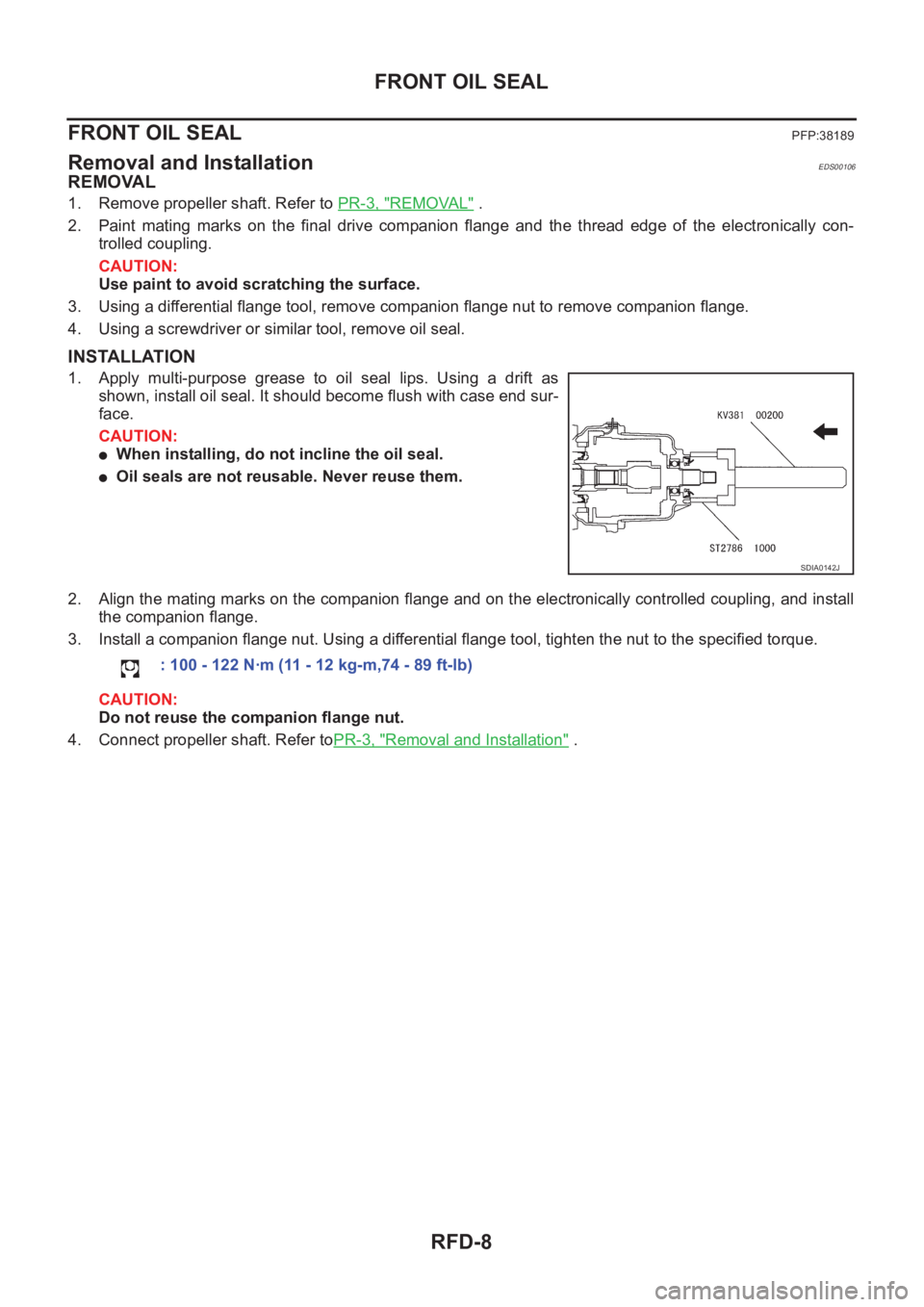
1. Apply multi-purpose grease to oil seal lips. Using a drift as
shown, install oil seal. It should become flush with case end sur-
face.
CAUTION:
●When installing, do not incline the oil seal.
●Oil seals are not reusable. Never reuse them.
2. Align the mating marks on the companion flange and on the electronically controlled coupling, and install
the companion flange.
3. Install a companion flange nut. Using a differential flange tool, tighten the nut to the specified torque.
CAUTION:
Do not reuse the companion flange nut.
4. Connect propeller shaft. Refer toPR-3, "
Removal and Installation" .
SDIA0142J
: 100 - 122 N·m (11 - 12 kg-m,74 - 89 ft-lb)
Page 2685 of 3833
SIDE OIL SEAL
RFD-9
C
E
F
G
H
I
J
K
L
MA
B
RFD
SIDE OIL SEALPFP:38343
Removal and InstallationEDS00107
REMOVAL
1. Remove drive shaft. Refer to RAX-9, "Removal" .
2. Using flat tip screwdriver as shown in the figure, remove oil seal.
INSTALLATION
1. Apply multi-purpose grease.to oil seal lips. Using a drift as
shown, install oil seal. It should become flush with case end sur-
face.
CAUTION:
●When installing, do not incline the oil seal.
●Oil seals are not reusable. Never reuse them.
2. Install drive shaft. Refer to RAX-9, "
Installation" .
PDIA0003E
PDIA0021E
Page 2686 of 3833
RFD-10
REAR COVER GASKET
REAR COVER GASKET
PFP:38320
ReplacementEDS00108
●Apply a continuous bead of sealant (Three bond 1217 or equiva-
lent) around the gear carrier mating surface on the coupling
cover as shown in the figure. Overlap both ends of the bead for
at least 3 mm.
CAUTION:
Remove old sealant on the mounting surface, then remove any
moisture, oil, and foreign material from the application and
mounting surfaces.
●Apply sealant (Three bond 1217 or the equivalent) around the
carrier case of rear cover as shown.
CAUTION:
Remove old sealant on the mounting surface, then remove any
moisture, oil, and foreign material from the application and
mounting surfaces.
SDIA0143E