2001 NISSAN X-TRAIL oil
[x] Cancel search: oilPage 2636 of 3833
TF-26
TRANSFER ASSEMBLY
Drive gear assembly
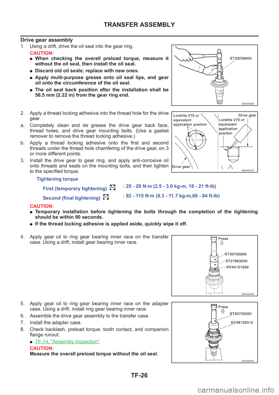
1. Using a drift, drive the oil seal into the gear ring.
CAUTION:
●When checking the overall preload torque, measure it
without the oil seal, then install the oil seal.
●Discard old oil seals; replace with new ones.
●Apply multi-purpose grease onto oil seal lips, and gear
oil onto the circumference of the oil seal.
●The oil seal back position after the installation shall be
56.5 mm (2.22 in) from the gear ring end.
2. Apply a thread locking adhesive into the thread hole for the drive
gear.
a. Completely clean and de grease the drive gear back face,
thread holes, and drive gear mounting bolts. (Use a gasket
remover to remove the thread locking adhesive.)
b. Apply a thread locking adhesive onto the first and second
threads under the thread hole chamfering of the drive gear, on 3
or more different points.
3. Install the drive gear to gear ring, and apply anti-corrosive oil
onto threads and seats on the mounting bolts, and then tighten
to the specified torque.
CAUTION:
●Temporary installation before tightening the bolts through the completion of the tightening
should be within 90 seconds.
●If the thread locking adhesive is applied aside, quickly wipe it off.
4. Apply gear oil to ring gear bearing inner race on the transfer
case. Using a drift, install gear bearing inner race.
5. Apply gear oil to ring gear bearing inner race on the adapter
case. Using a drift, install ring gear bearing inner race.
6. Assemble the drive gear assembly to the transfer case.
7. Install the adapter case.
8. Check backlash, preload torque, tooth contact, and companion
flange runout.
●TF-14, "Assembly Inspection".
CAUTION:
Measure the overall preload torque without the oil seal.
SDIA0540E
Tightening torque
First (temporary tightening) : 25 - 29 N·m (2.5 - 3.0 kg-m, 18 - 21 ft-lb)
Second (final tightening) : 82 - 115 N·m (8.3 - 11.7 kg-m,60 - 84 ft-lb)
SDIA0541E
SDIA0543E
SDIA0544E
Page 2637 of 3833
TRANSFER ASSEMBLY
TF-27
C
E
F
G
H
I
J
K
L
MA
B
TF
Adapter case
1. Select the adjusting shim on the gear ring bearing.
●TF-23, "SELECTIONG ADJUSTING SHIMS".
2. Install the oil gutter.
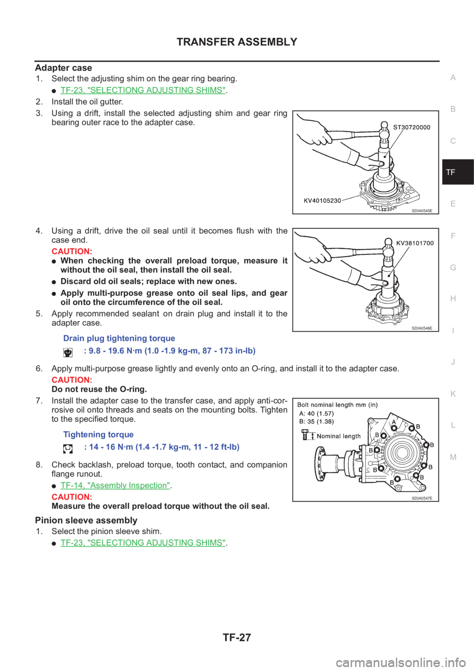
3. Using a drift, install the selected adjusting shim and gear ring
bearing outer race to the adapter case.
4. Using a drift, drive the oil seal until it becomes flush with the
case end.
CAUTION:
●When checking the overall preload torque, measure it
without the oil seal, then install the oil seal.
●Discard old oil seals; replace with new ones.
●Apply multi-purpose grease onto oil seal lips, and gear
oil onto the circumference of the oil seal.
5. Apply recommended sealant on drain plug and install it to the
adapter case.
6. Apply multi-purpose grease lightly and evenly onto an O-ring, and install it to the adapter case.
CAUTION:
Do not reuse the O-ring.
7. Install the adapter case to the transfer case, and apply anti-cor-
rosive oil onto threads and seats on the mounting bolts. Tighten
to the specified torque.
8. Check backlash, preload torque, tooth contact, and companion
flange runout.
●TF-14, "Assembly Inspection".
CAUTION:
Measure the overall preload torque without the oil seal.
Pinion sleeve assembly
1. Select the pinion sleeve shim.
●TF-23, "SELECTIONG ADJUSTING SHIMS".
SDIA0545E
Drain plug tightening torque
: 9.8 - 19.6 N·m (1.0 -1.9 kg-m, 87 - 173 in-lb)
Tightening torque
: 14 - 16 N·m (1.4 -1.7 kg-m, 11 - 12 ft-lb)
SDIA0546E
SDIA0547E
Page 2638 of 3833
TF-28
TRANSFER ASSEMBLY
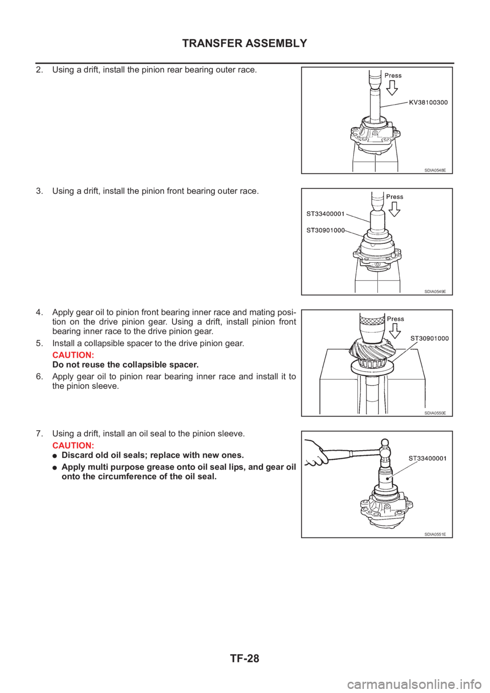
2. Using a drift, install the pinion rear bearing outer race.
3. Using a drift, install the pinion front bearing outer race.
4. Apply gear oil to pinion front bearing inner race and mating posi-
tion on the drive pinion gear. Using a drift, install pinion front
bearing inner race to the drive pinion gear.
5. Install a collapsible spacer to the drive pinion gear.
CAUTION:
Do not reuse the collapsible spacer.
6. Apply gear oil to pinion rear bearing inner race and install it to
the pinion sleeve.
7. Using a drift, install an oil seal to the pinion sleeve.
CAUTION:
●Discard old oil seals; replace with new ones.
●Apply multi purpose grease onto oil seal lips, and gear oil
onto the circumference of the oil seal.
SDIA0548E
SDIA0549E
SDIA0550E
SDIA0551E
Page 2639 of 3833
TRANSFER ASSEMBLY
TF-29
C
E
F
G
H
I
J
K
L
MA
B
TF
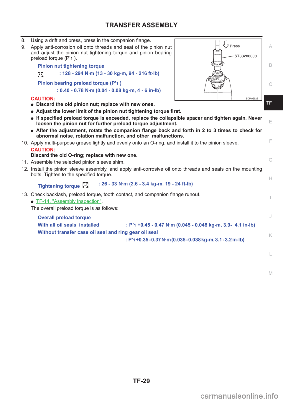
8. Using a drift and press, press in the companion flange.
9. Apply anti-corrosion oil onto threads and seat of the pinion nut
and adjust the pinion nut tightening torque and pinion bearing
preload torque (P’
1 ).
CAUTION:
●Discard the old pinion nut; replace with new ones.
●Adjust the lower limit of the pinion nut tightening torque first.
●If specified preload torque is exceeded, replace the collapsible spacer and tighten again. Never
loosen the pinion nut for further preload torque adjustment.
●After the adjustment, rotate the companion flange back and forth in 2 to 3 times to check for
abnormal noise, rotation malfunction, and other malfunctions.
10. Apply multi-purpose grease lightly and evenly onto an O-ring, and install it to the pinion sleeve.
CAUTION:
Discard the old O-ring; replace with new one.
11. Assemble the selected pinion sleeve shim.
12. Install the pinion sleeve assembly, and apply anti-corrosive oil onto threads and seats on the mounting
bolts. Tighten to the specified torque.
13. Check backlash, preload torque, tooth contact, and companion flange runout.
●TF-14, "Assembly Inspection".
The overall preload torque is as follows:Pinion nut tightening torque
: 128 - 294 N·m (13 - 30 kg-m, 94 - 216 ft-lb)
Pinion bearing preload torque (P’
1 )
: 0.40 - 0.78 N·m (0.04 - 0.08 kg-m, 4 - 6 in-lb)
Tightening torque : 26 - 33 N·m (2.6 - 3.4 kg-m, 19 - 24 ft-lb)
Overall preload torque
With all oil seals installed : P’
1 +0.45 - 0.47 N·m (0.045 - 0.048 kg-m, 3.9- 4.1 in-lb)
Without transfer case oil seal and ring gear oil seal
: P’
1 + 0 . 3 5 - 0 . 3 7 N · m ( 0 . 0 3 5 - 0 . 0 3 8 k g - m , 3 . 1 - 3 . 2 i n - l b )
SDIA0552E
Page 2641 of 3833
ALL MODE 4X4 SYSTEM
TF-31
C
E
F
G
H
I
J
K
L
MA
B
TF
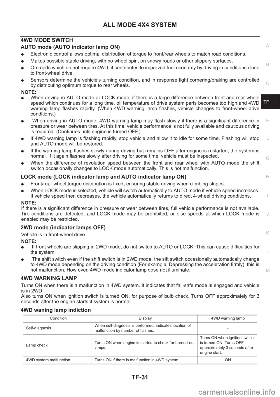
4WD MODE SWITCH
AUTO mode (AUTO indicator lamp ON)
●Electronic control allows optimal distribution of torque to front/rear wheels to match road conditions.
●Makes possible stable driving, with no wheel spin, on snowy roads or other slippery surfaces.
●On roads which do not require 4WD, it contributes to improved fuel economy by driving in conditions close
to front-wheel drive.
●Sensors determine the vehicle's turning condition, and in response tight cornering/braking are controlled
by distributing optimum torque to rear wheels.
NOTE:
●When driving in AUTO mode or LOCK mode, if there is a large difference between front and rear wheel
speed which continues for a long time, oil temperature of drive system parts becomes too high and 4WD
warning lamp flashes rapidly. (When 4WD warning lamp flashes, vehicle changes to front-wheel drive
conditions.)
● When driving in AUTO mode, 4WD warning lamp may flash slowly if there is a significant difference in
pressure or wear between tires. At this time, vehicle performance is not fully available and cautious driving
is required. (Continues until engine is turned OFF.)
●If 4WD warning lamp is flashing rapidly, stop vehicle and allow it to idle for some time. Flashing will stop
and AUTO mode will be restored.
●If the warning lamp flashes slowly during driving but remains OFF after engine is restarted, the system is
normal. If it again flashes slowly after driving for some time, vehicle must be inspected.
●When the difference of revolution speed between the front and rear wheel with AUTO mode the shift
switch occasionally changes to LOCK mode automatically. This is not malfunction.
LOCK mode (LOCK indicator lamp and AUTO indicator lamp ON)
●Front/rear wheel torque distribution is fixed, ensuring stable driving when climbing slopes.
●When LOCK mode is selected, vehicle will switch automatically to AUTO mode if vehicle speed increases.
If vehicle speed then decreases, the vehicle automatically returns to direct 4-wheel driving conditions.
NOTE:
If there is a significant difference in pressure or wear between tires, full vehicle performance is not available.
Tire conditions are detected, and LOCK mode may be prohibited, or else speeds at which LOCK mode is
enabled may be restricted.
2WD mode (indicator lamps OFF)
Vehicle is in front-wheel drive.
NOTE:
● If front wheels are slipping in 2WD mode, do not switch to AUTO or LOCK. This can cause difficulties for
the system.
● The shift switch even if the shift switch is in 2WD mode, the sift switch occasionally automatically change
to 4WD mode depending on the driving condition (For example; Depressing the acceleration firmly). this is
not malfunction. How ever, 4WD mode indicator lamp dose not illuminate.
4WD WARNING LAMP
Turns ON when there is a malfunction in 4WD system. It indicates that fail-safe mode is engaged and vehicle
is in 2WD.
Also turns ON when ignition switch is turned ON, for purpose of bulb check. Turns OFF approximately for 3
seconds after the engine starts if system is normal.
4WD waning lamp indiction
Condition Display 4WD warning lamp
Self-diagnosisWhen self-diagnosis is performed, indicates location of
malfunction by number of flashes.-
Lamp checkTurns ON when engine is started to check for burned-out
lamps.Turns ON when ignition switch
is turned ON. Turns OFF
approximately 3 seconds after
engine start.
4WD system malfunction Turns ON if there is malfunction in 4WD system. ON
Page 2642 of 3833
TF-32
ALL MODE 4X4 SYSTEM
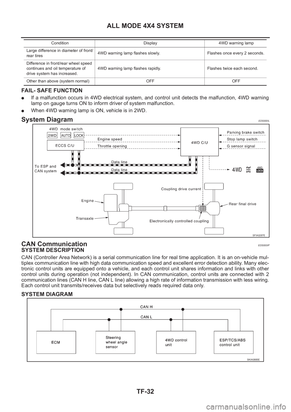
FAIL- SAFE FUNCTION
●If a malfunction occurs in 4WD electrical system, and control unit detects the malfunction, 4WD warning
lamp on gauge turns ON to inform driver of system malfunction.
●When 4WD warning lamp is ON, vehicle is in 2WD.
System DiagramEDS000IL
CAN CommunicationEDS000IP
SYSTEM DESCRIPTION
CAN (Controller Area Network) is a serial communication line for real time application. It is an on-vehicle mul-
tiplex communication line with high data communication speed and excellent error detection ability. Many elec-
tronic control units are equipped onto a vehicle, and each control unit shares information and links with other
control units during operation (not independent). In CAN communication, control units are connected with 2
communication lines (CAN H line, CAN L line) allowing a high rate of information transmission with less wiring.
Each control unit transmits/receives data but selectively reads required data only.
SYSTEM DIAGRAM
Large difference in diameter of front/
rear tires4WD warning lamp flashes slowly. Flashes once every 2 seconds.
Difference in front/rear wheel speed
continues and oil temperature of
drive system has increased.4WD warning lamp flashes rapidly. Flashes twice each second.
Other than above (system normal) OFF OFFCondition Display 4WD warning lamp
SFIA0287E
SKIA0885E
Page 2669 of 3833
SERVICE DATA AND SPECIFICATIONS (SDS)
TF-59
C
E
F
G
H
I
J
K
L
MA
B
TF
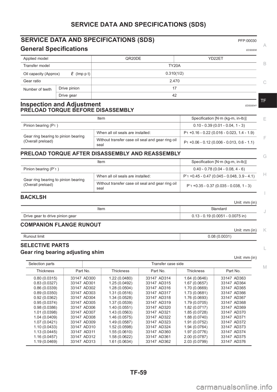
SERVICE DATA AND SPECIFICATIONS (SDS)PFP:00030
General SpecificationsEDS000I6
Inspection and AdjustmentEDS0004Y
PRELOAD TORQUE BEFORE DISASSEMBLY
PRELOAD TORQUE AFTER DISASSEMBLY AND REASSEMBLY
BACKLSH
Unit: mm (in)
COMPANION FLANGE RUNOUT
Unit: mm (in)
SELECTIVE PARTS
Gear ring bearing adjusting shim
Unit: mm (in) Applied model QR20DE YD22ET
Transfer model TY20A
Oil capacity (Approx) (lmp p t)0.310(1/2)
Gear ratio2.470
Number of teeth Drive pinion 17
Drive gear 42
Item Specification [N·m (kg-m, in-lb)]
Pinion bearing (P
1 )0.10 - 0.39 (0.01 - 0.04, 1 - 3)
Gear ring bearing to pinion bearing
(Overall preload)When all oil seals are installed: P
1 +0.16 - 0.22 (0.016 - 0.023, 1.4 - 1.9)
Without transfer case oil seal and gear ring oil
sealP
1 +0.06 - 0.12 (0.006 - 0.013, 0.6 - 1.1)
Item Specification [N·m (kg-m, in-lb)]
Pinion bearing (P’
1 )0.40 - 0.78 (0.04 - 0.08, 4 - 6)
Gear ring bearing to pinion bearing
(Overall preload)When all oil seals are installed: P’
1 +0.45 - 0.47 (0.045 - 0.048, 3.9 - 4.1)
Without transfer case oil seal and gear ring oil
sealP’
1 +0.35 - 0.37 (0.035 - 0.038, 1 - 3)
Item Standard
Drive gear to drive pinion gear 0.13 - 0.19 (0.0051 - 0.0075 in)
Runout limit 0.08 (0.0031)
Selection parts Transfer case side
Thickness Part No. Thickness Part No. Thickness Part No.
0.80 (0.0315)
0.83 (0.0327)
0.86 (0.0339)
0.89 (0.0350)
0.92 (0.0362)
0.95 (0.0374)
0.98 (0.0386)
1.01 (0.0398)
1.04 (0.0409)
1.07 (0.0421)
1.10 (0.0433)
1.13 (0.0445)
1.16 (0.0457)
1.19 (0.0469)33147 AD300
33147 AD301
33147 AD302
33147 AD303
33147 AD304
33147 AD305
33147 AD306
33147 AD307
33147 AD308
33147 AD309
33147 AD310
33147 AD311
33147 AD312
33147 AD3131.22 (0.0480)
1.25 (0.0492)
1.28 (0.0504)
1.31 (0.0516)
1.34 (0.0528)
1.37 (0.0539)
1.40 (0.0551)
1.43 (0.0563)
1.46 (0.0575)
1.49 (0.0587)
1.52 (0.0598)
1.55 (0.0610)
1.58 (0.0622)
1.61 (0.0634)33147 AD314
33147 AD315
33147 AD316
33147 AD317
33147 AD318
33147 AD319
33147 AD320
33147 AD321
33147 AD322
33147 AD323
33147 AD324
33147 AD360
33147 AD361
33147 AD3621.64 (0.0646)
1.67 (0.0657)
1.70 (0.0669)
1.73 (0.0681)
1.76 (0.0693)
1.79 (0.0705)
1.82 (0.0717)
1.85 (0.0728)
1.88 (0.0740)
1.91 (0.0752)
1.94 (0.0764)
1.97 (0.0776)
2.00 (0.0787)
2.03 (0.0799)33147 AD363
33147 AD364
33147 AD365
33147 AD366
33147 AD367
33147 AD368
33147 AD369
33147 AD370
33147 AD371
33147 AD372
33147 AD373
33147 AD374
33147 AD375
33147 AD376
Page 2677 of 3833
RFD-1
REAR FINAL DRIVE
D DRIVELINE/AXLE
CONTENTS
C
E
F
G
H
I
J
K
L
M
SECTION
A
B
RFD
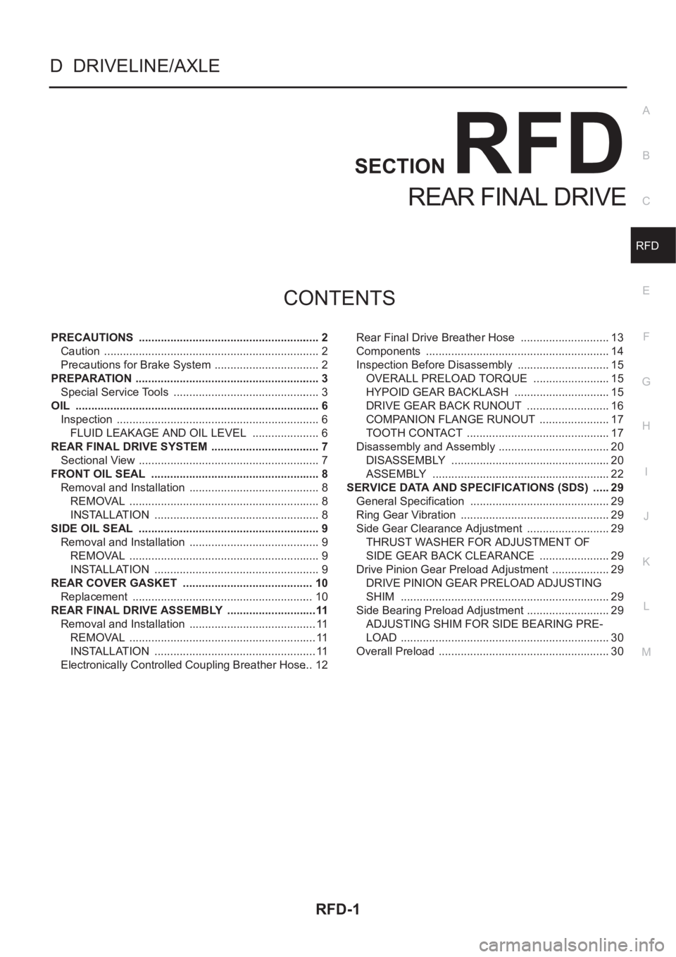
REAR FINAL DRIVE
PRECAUTIONS .......................................................... 2
Caution ..................................................................... 2
Precautions for Brake System .................................. 2
PREPARATION ........................................................... 3
Special Service Tools ............................................... 3
OIL .............................................................................. 6
Inspection ................................................................. 6
FLUID LEAKAGE AND OIL LEVEL ...................... 6
REAR FINAL DRIVE SYSTEM ................................... 7
Sectional View .......................................................... 7
FRONT OIL SEAL ................................................. ..... 8
Removal and Installation .......................................... 8
REMOVAL ............................................................. 8
INSTALLATION ..................................................... 8
SIDE OIL SEAL .......................................................... 9
Removal and Installation .......................................... 9
REMOVAL ............................................................. 9
INSTALLATION ..................................................... 9
REAR COVER GASKET .......................................... 10
Replacement .......................................................... 10
REAR FINAL DRIVE ASSEMBLY .............................11
Removal and Installation ......................................... 11
REMOVAL ............................................................ 11
INSTALLATION .................................................... 11
Electronically Controlled Coupling Breather Hose ... 12Rear Final Drive Breather Hose ............................. 13
Components ........................................................... 14
Inspection Before Disassembly .............................. 15
OVERALL PRELOAD TORQUE ......................... 15
HYPOID GEAR BACKLASH ............................... 15
DRIVE GEAR BACK RUNOUT ........................... 16
COMPANION FLANGE RUNOUT ....................... 17
TOOTH CONTACT .............................................. 17
Disassembly and Assembly .................................... 20
DISASSEMBLY ................................................... 20
ASSEMBLY ......................................................... 22
SERVICE DATA AND SPECIFICATIONS (SDS) ...... 29
General Specification ............................................. 29
Ring Gear Vibration ................................................ 29
Side Gear Clearance Adjustment ........................... 29
THRUST WASHER FOR ADJUSTMENT OF
SIDE GEAR BACK CLEARANCE ....................... 29
Drive Pinion Gear Preload Adjustment ................... 29
DRIVE PINION GEAR PRELOAD ADJUSTING
SHIM ................................................................... 29
Side Bearing Preload Adjustment ........................... 29
ADJUSTING SHIM FOR SIDE BEARING PRE-
LOAD ................................................................... 30
Overall Preload ....................................................... 30