2001 NISSAN X-TRAIL clutch
[x] Cancel search: clutchPage 256 of 3833
![NISSAN X-TRAIL 2001 Service Repair Manual EM-206
[YD22DDTi]
CYLINDER BLOCK
●There is a mating mark on the clutch cover side, Refer it dur-
ing installation.
●Holding ring gear with ring stopper (SST), tighten securing bolts with TORX bit NISSAN X-TRAIL 2001 Service Repair Manual EM-206
[YD22DDTi]
CYLINDER BLOCK
●There is a mating mark on the clutch cover side, Refer it dur-
ing installation.
●Holding ring gear with ring stopper (SST), tighten securing bolts with TORX bit](/manual-img/5/57405/w960_57405-255.png)
EM-206
[YD22DDTi]
CYLINDER BLOCK
●There is a mating mark on the clutch cover side, Refer it dur-
ing installation.
●Holding ring gear with ring stopper (SST), tighten securing bolts with TORX bit (size: Q6T55 E9, Com-
mercial Service Tool).
●Tighten bolts uniformly in a crisscross manner.
How to Select Piston and BearingEBS00ODY
DESCRIPTION
●The identification grade stamped on each part is the grade for the dimension measured in new condition.
This grade cannot apply to reused parts.
●For reused or repaired parts, measure the dimension accurately. Determine the grade by comparing the
measurement with the values of each selection table.
●For details of the measurement method of each part, the reuse standards and the selection method of the
selective fitting parts, refer to the text.
HOW TO SELECT PISTON
When Using New Cylinder Block
1. Identify the cylinder bore grade (No. 1, 2, or 3) on LH surface at
the rear of cylinder block.
2. Select the piston of the same grade.
●The part No. of piston is specified together with the piston pin
as an assembly.
PBIC0981E
Selection points Selection parts Selection items Selection methods
Between cylinder block to
crankshaftMain bearingMain bearing grade (bearing
thickness)Determined by match of cylin-
der block bearing housing
grade (inner diameter of hous-
ing) and crankshaft journal
grade (outer diameter of jour-
nal)
Between crankshaft to connect-
ing rodConnecting rod bearingConnecting rod bearing grade
(bearing thickness)Combining service grades for
connecting rod bearing and
crankshaft pin outer diameter
determine connecting rod bear-
ing selection.
Between cylinder block to pis-
tonPiston and piston pin assembly
The piston is available together
with piston pin as an assembly.Piston grade (piston outer
diameter)Piston grade = cylinder bore
grade (inner diameter of bore)
JEM208G
Page 268 of 3833
![NISSAN X-TRAIL 2001 Service Repair Manual EM-218
[YD22DDTi]
CYLINDER BLOCK
OIL JET
●Check nozzle for deformation and damage.
●Blow compressed air from nozzle, and check for clogs.
●If it out of the standard, replace oil jet.
OIL JET REL NISSAN X-TRAIL 2001 Service Repair Manual EM-218
[YD22DDTi]
CYLINDER BLOCK
OIL JET
●Check nozzle for deformation and damage.
●Blow compressed air from nozzle, and check for clogs.
●If it out of the standard, replace oil jet.
OIL JET REL](/manual-img/5/57405/w960_57405-267.png)
EM-218
[YD22DDTi]
CYLINDER BLOCK
OIL JET
●Check nozzle for deformation and damage.
●Blow compressed air from nozzle, and check for clogs.
●If it out of the standard, replace oil jet.
OIL JET RELIEF VALVE
●Using a clean plastic stick, press check valve in oil jet relief
valve. Make sure that valve moves smoothly with proper reac-
tion force.
●If it is out of the standard, replace oil jet relief valve.
MOVEMENT AMOUNT OF FLYWHEEL
NOTE:
●Inspection for double mass flywheel only.
●Do not disassembly double mass flywheel.
Flywheel Deflection
●Measure deflection of flywheel contact surface to the clutch with a dial gauge.
●Measure deflection at 210 mm (8.27 in) dia.
●When measured value exceeds the limit, replace flywheel with a
new one.
Movement Amount in Radial (rotation) Direction
Check the movement amount in the following procedure.
1. Install a bolt to clutch cover mounting hole, and place a torque wrench on the extended line of the flywheel
center line.
●Tighten bolt at a force of 9.8 N·m (1 kg-m, 87 in-lb) to keep it from loosening. Standard : Deformation and damage.
JEM221G
Standard:
Valve moves smoothly with proper reaction force.
JEM222G
Standard : 0.45 mm (0.0177 in) or less
Limit : 1.3 mm (0.051 in)
PBIC0683E
Page 1959 of 3833
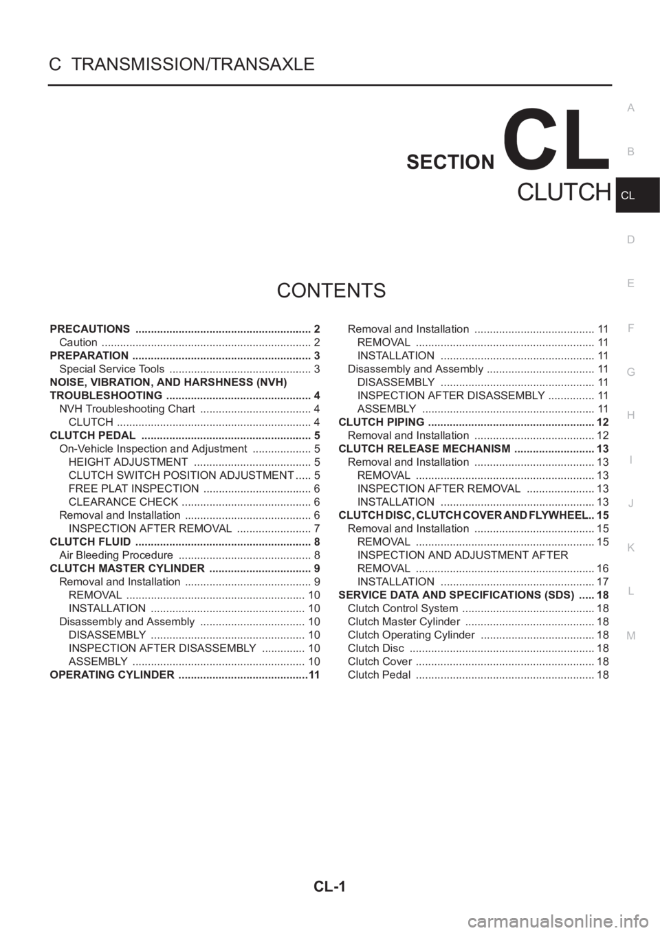
CL-1
CLUTCH
C TRANSMISSION/TRANSAXLE
CONTENTS
D
E
F
G
H
I
J
K
L
M
SECTION
A
B
CL
CLUTCH
PRECAUTIONS .......................................................... 2
Caution ..................................................................... 2
PREPARATION ........................................................... 3
Special Service Tools ............................................... 3
NOISE, VIBRATION, AND HARSHNESS (NVH)
TROUBLESHOOTING ................................................ 4
NVH Troubleshooting Chart ..................................... 4
CLUTCH ................................................................ 4
CLUTCH PEDAL ........................................................ 5
On-Vehicle Inspection and Adjustment .................... 5
HEIGHT ADJUSTMENT ....................................... 5
CLUTCH SWITCH POSITION ADJUSTMENT ..... 5
FREE PLAT INSPECTION .................................... 6
CLEARANCE CHECK ........................................... 6
Removal and Installation .......................................... 6
INSPECTION AFTER REMOVAL ......................... 7
CLUTCH FLUID .......................................................... 8
Air Bleeding Procedure ............................................ 8
CLUTCH MASTER CYLINDER .................................. 9
Removal and Installation .......................................... 9
REMOVAL ........................................................... 10
INSTALLATION ................................................... 10
Disassembly and Assembly ................................... 10
DISASSEMBLY ................................................... 10
INSPECTION AFTER DISASSEMBLY ............... 10
ASSEMBLY ......................................................... 10
OPERATING CYLINDER ...........................................11Removal and Installation ........................................ 11
REMOVAL ........................................................... 11
INSTALLATION ................................................... 11
Disassembly and Assembly .................................... 11
DISASSEMBLY ................................................... 11
INSPECTION AFTER DISASSEMBLY ................ 11
ASSEMBLY ......................................................... 11
CLUTCH PIPING ....................................................... 12
Removal and Installation ........................................ 12
CLUTCH RELEASE MECHANISM ........................... 13
Removal and Installation ........................................ 13
REMOVAL ........................................................... 13
INSPECTION AFTER REMOVAL ....................... 13
INSTALLATION ................................................... 13
CLUTCH DISC, CLUTCH COVER AND FLYWHEEL ... 15
Removal and Installation ........................................ 15
REMOVAL ........................................................... 15
INSPECTION AND ADJUSTMENT AFTER
REMOVAL ........................................................... 16
INSTALLATION ................................................... 17
SERVICE DATA AND SPECIFICATIONS (SDS) ...... 18
Clutch Control System ............................................ 18
Clutch Master Cylinder ........................................... 18
Clutch Operating Cylinder ...................................... 18
Clutch Disc ............................................................. 18
Clutch Cover ........................................................... 18
Clutch Pedal ........................................................... 18
Page 1960 of 3833
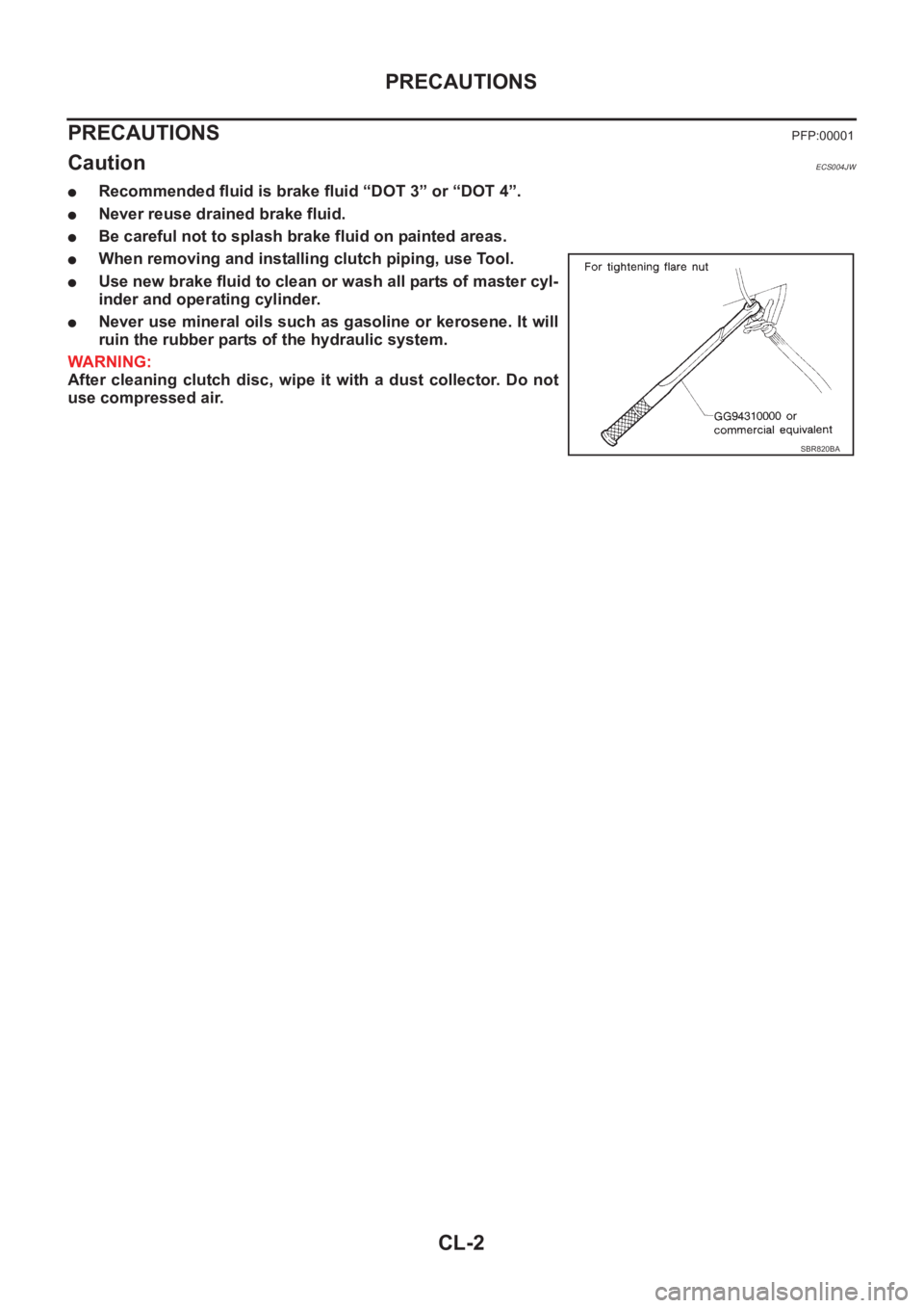
CL-2
PRECAUTIONS
PRECAUTIONS
PFP:00001
CautionECS004JW
●Recommended fluid is brake fluid “DOT 3” or “DOT 4”.
●Never reuse drained brake fluid.
●Be careful not to splash brake fluid on painted areas.
●When removing and installing clutch piping, use Tool.
●Use new brake fluid to clean or wash all parts of master cyl-
inder and operating cylinder.
●Never use mineral oils such as gasoline or kerosene. It will
ruin the rubber parts of the hydraulic system.
WARNING:
After cleaning clutch disc, wipe it with a dust collector. Do not
use compressed air.
SBR820BA
Page 1961 of 3833
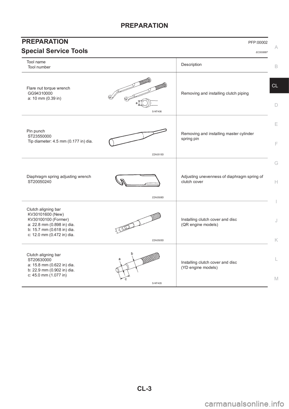
PREPARATION
CL-3
D
E
F
G
H
I
J
K
L
MA
B
CL
PREPARATIONPFP:00002
Special Service ToolsECS008B7
Tool name
Tool numberDescription
Flare nut torque wrench
GG94310000
a: 10 mm (0.39 in)Removing and installing clutch piping
Pin punch
ST23550000
Tip diameter: 4.5 mm (0.177 in) dia.Removing and installing master cylinder
spring pin
Diaphragm spring adjusting wrench
ST20050240Adjusting unevenness of diaphragm spring of
clutch cover
Clutch aligning bar
KV30101600 (New)
KV30100100 (Former)
a: 22.8 mm (0.898 in) dia.
b: 15.7 mm (0.618 in) dia.
c: 12.0 mm (0.472 in) dia.Installing clutch cover and disc
(QR engine models)
Clutch aligning bar
ST20630000
a: 15.8 mm (0.622 in) dia.
b: 22.9 mm (0.902 in) dia.
c: 45.0 mm (1.077 in)Installing clutch cover and disc
(YD engine models)
S-NT406
ZZA0515D
ZZA0508D
ZZA0505D
S-NT405
Page 1962 of 3833
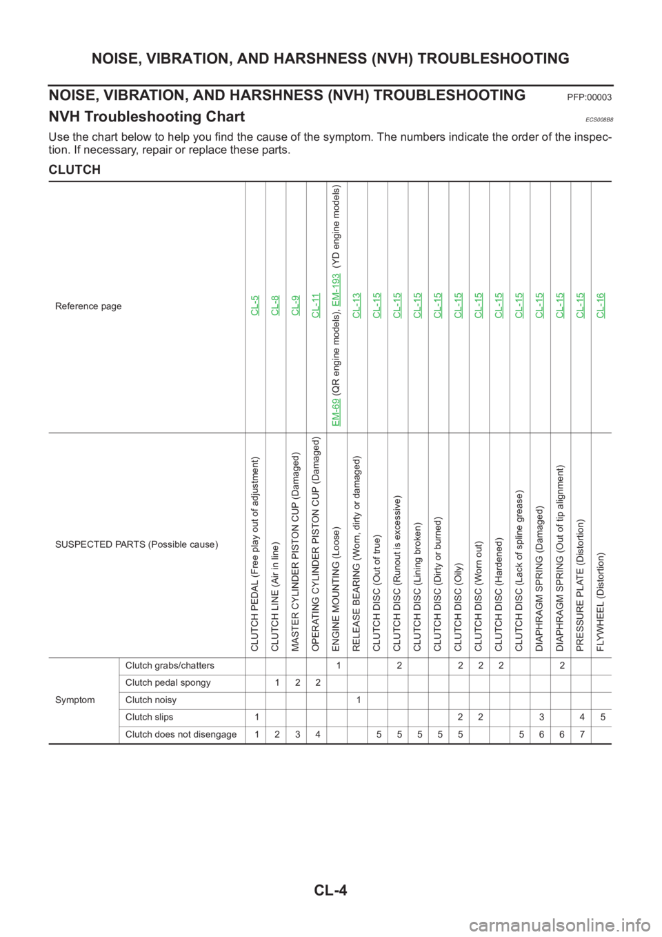
CL-4
NOISE, VIBRATION, AND HARSHNESS (NVH) TROUBLESHOOTING
NOISE, VIBRATION, AND HARSHNESS (NVH) TROUBLESHOOTING
PFP:00003
NVH Troubleshooting ChartECS008B8
Use the chart below to help you find the cause of the symptom. The numbers indicate the order of the inspec-
tion. If necessary, repair or replace these parts.
CLUTCH
Reference pageCL-5CL-8CL-9CL-11
EM-69
(QR engine models), EM-193
(YD engine models)
CL-13
CL-15CL-15CL-15CL-15CL-15CL-15CL-15CL-15CL-15CL-15CL-15CL-16
SUSPECTED PARTS (Possible cause)
CLUTCH PEDAL (Free play out of adjustment)
CLUTCH LINE (Air in line)
MASTER CYLINDER PISTON CUP (Damaged)
OPERATING CYLINDER PISTON CUP (Damaged)
ENGINE MOUNTING (Loose)
RELEASE BEARING (Worn, dirty or damaged)
CLUTCH DISC (Out of true)
CLUTCH DISC (Runout is excessive)
CLUTCH DISC (Lining broken)
CLUTCH DISC (Dirty or burned)
CLUTCH DISC (Oily)
CLUTCH DISC (Worn out)
CLUTCH DISC (Hardened)
CLUTCH DISC (Lack of spline grease)
DIAPHRAGM SPRING (Damaged)
DIAPHRAGM SPRING (Out of tip alignment)
PRESSURE PLATE (Distortion)
FLYWHEEL (Distortion)
SymptomClutch grabs/chatters 1 2 2 2 2 2
Clutch pedal spongy 1 2 2
Clutch noisy 1
Clutch slips 1 2 2 3 4 5
Clutch does not disengage 1 2 3 4 5 5 5 5 5 5 6 6 7
Page 1963 of 3833
CLUTCH PEDAL
CL-5
D
E
F
G
H
I
J
K
L
MA
B
CL
CLUTCH PEDALPFP:46540
On-Vehicle Inspection and AdjustmentECS001WB
HEIGHT ADJUSTMENT
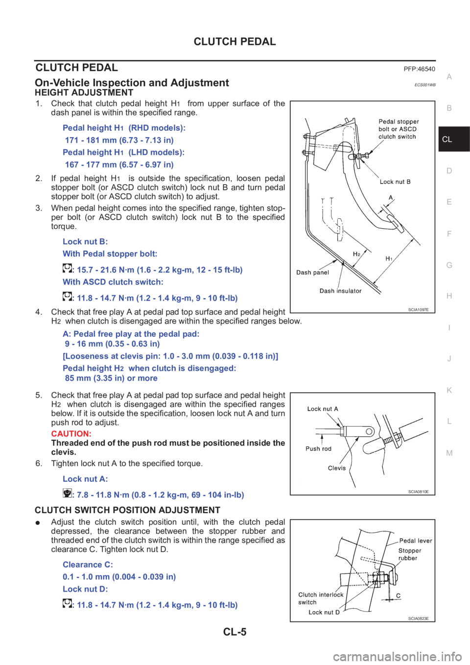
1. Check that clutch pedal height H1 from upper surface of the
dash panel is within the specified range.
2. If pedal height H
1 is outside the specification, loosen pedal
stopper bolt (or ASCD clutch switch) lock nut B and turn pedal
stopper bolt (or ASCD clutch switch) to adjust.
3. When pedal height comes into the specified range, tighten stop-
per bolt (or ASCD clutch switch) lock nut B to the specified
torque.
4. Check that free play A at pedal pad top surface and pedal height
H
2 when clutch is disengaged are within the specified ranges below.
5. Check that free play A at pedal pad top surface and pedal height
H
2 when clutch is disengaged are within the specified ranges
below. If it is outside the specification, loosen lock nut A and turn
push rod to adjust.
CAUTION:
Threaded end of the push rod must be positioned inside the
clevis.
6. Tighten lock nut A to the specified torque.
CLUTCH SWITCH POSITION ADJUSTMENT
●Adjust the clutch switch position until, with the clutch pedal
depressed, the clearance between the stopper rubber and
threaded end of the clutch switch is within the range specified as
clearance C. Tighten lock nut D.Pedal height H
1 (RHD models):
171 - 181 mm (6.73 - 7.13 in)
Pedal height H
1 (LHD models):
167 - 177 mm (6.57 - 6.97 in)
Lock nut B:
With Pedal stopper bolt:
: 15.7 - 21.6 N·m (1.6 - 2.2 kg-m, 12 - 15 ft-lb)
With ASCD clutch switch:
: 11.8 - 14.7 N·m (1.2 - 1.4 kg-m, 9 - 10 ft-lb)
A: Pedal free play at the pedal pad:
9 - 16 mm (0.35 - 0.63 in)
[Looseness at clevis pin: 1.0 - 3.0 mm (0.039 - 0.118 in)]
Pedal height H
2 when clutch is disengaged:
85 mm (3.35 in) or more
SCIA1097E
Lock nut A:
: 7.8 - 11.8 N·m (0.8 - 1.2 kg-m, 69 - 104 in-lb)
SCIA0810E
Clearance C:
0.1 - 1.0 mm (0.004 - 0.039 in)
Lock nut D:
: 11.8 - 14.7 N·m (1.2 - 1.4 kg-m, 9 - 10 ft-lb)
SCIA0823E
Page 1964 of 3833
CL-6
CLUTCH PEDAL
FREE PLAT INSPECTION
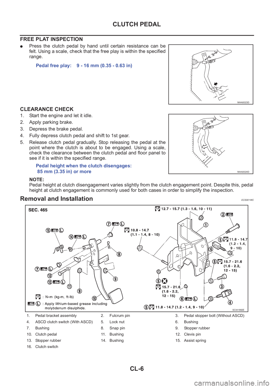
●Press the clutch pedal by hand until certain resistance can be
felt. Using a scale, check that the free play is within the specified
range.
CLEARANCE CHECK
1. Start the engine and let it idle.
2. Apply parking brake.
3. Depress the brake pedal.
4. Fully depress clutch pedal and shift to 1st gear.
5. Release clutch pedal gradually. Stop releasing the pedal at the
point where the clutch is about to be engaged. Using a scale,
check the clearance between the clutch pedal and floor panel to
see if it is within the specified range.
NOTE:
Pedal height at clutch disengagement varies slightly from the clutch engagement point. Despite this, pedal
height at clutch engagement is commonly used for both cases in order to simplify the inspection.
Removal and InstallationECS001WC
Pedal free play: 9 - 16 mm (0.35 - 0.63 in)
MAA0023D
Pedal height when the clutch disengages:
85 mm (3.35 in) or more
MAA0024D
1. Pedal bracket assembly 2. Fulcrum pin 3. Pedal stopper bolt (Without ASCD)
4. ASCD clutch switch (With ASCD) 5. Lock nut 6. Bushing
7. Bushing 8. Snap pin 9. Stopper rubber
10. Clutch pedal 11. Bushing 12. Clevis pin
13. Stopper rubber 14. Bushing 15. Assist spring
16. Clutch switch
SCIA1882E