Page 1973 of 3833
CLUTCH DISC, CLUTCH COVER AND FLYWHEEL
CL-15
D
E
F
G
H
I
J
K
L
MA
B
CL
CLUTCH DISC, CLUTCH COVER AND FLYWHEELPFP:30100
Removal and InstallationECS008BG
—QR engine models—
—YD engine models—
CAUTION:
Be careful not to bring any grease into contact with the clutch disc facing, pressure plate surface, or
flywheel surface.
REMOVAL
1. Remove manual transaxle from the vehicle.
●Refer to MT-15, "Removal and Installation" .
2. Loosen clutch cover mounting bolts evenly. Remove clutch cover and clutch disc.
SCIA0329E
SCIA0813E
Page 1974 of 3833

CL-16
CLUTCH DISC, CLUTCH COVER AND FLYWHEEL
INSPECTION AND ADJUSTMENT AFTER REMOVAL
Clutch Disc
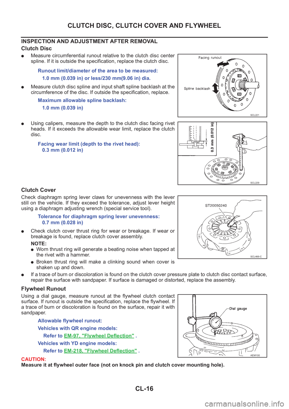
●Measure circumferential runout relative to the clutch disc center
spline. If it is outside the specification, replace the clutch disc.
●Measure clutch disc spline and input shaft spline backlash at the
circumference of the disc. If outside the specification, replace.
●Using calipers, measure the depth to the clutch disc facing rivet
heads. If it exceeds the allowable wear limit, replace the clutch
disc.
Clutch Cover
Check diaphragm spring lever claws for unevenness with the lever
still on the vehicle. If they exceed the tolerance, adjust lever height
using a diaphragm adjusting wrench (special service tool).
●Check clutch cover thrust ring for wear or breakage. If wear or
breakage is found, replace clutch cover assembly.
NOTE:
●Worn thrust ring will generate a beating noise when tapped at
the rivet with a hammer.
●Broken thrust ring will make a clinking sound when cover is
shaken up and down.
●If a trace of burn or discoloration is found on the clutch cover pressure plate to clutch disc contact surface,
repair the surface with sandpaper. If surface is damaged or distorted, replace the assembly.
Flywheel Runout
Using a dial gauge, measure runout at the flywheel clutch contact
surface. If runout is outside the specification, replace the flywheel. If
a trace of burn or discoloration is found on the surface, repair it with
sandpaper.
CAUTION:
Measure it at flywheel outer face (not on knock pin and clutch cover mounting hole). Runout limit/diameter of the area to be measured:
1.0 mm (0.039 in) or less/230 mm(9.06 in) dia.
Maximum allowable spline backlash:
1.0 mm (0.039 in)
SCL221
Facing wear limit (depth to the rivet head):
0.3 mm (0.012 in)
SCL229
Tolerance for diaphragm spring lever unevenness:
0.7 mm (0.028 in)
SCL466-C
Allowable flywheel runout:
Vehicles with QR engine models:
Refer to EM-97, "
Flywheel Deflection" .
Vehicles with YD engine models:
Refer to EM-218, "
Flywheel Deflection" .AEM100
Page 1975 of 3833
CLUTCH DISC, CLUTCH COVER AND FLYWHEEL
CL-17
D
E
F
G
H
I
J
K
L
MA
B
CL
INSTALLATION
1. Apply recommended grease to clutch disc and input shaft splines.
CAUTION:
Be sure to apply grease to the points specified. Otherwise, noise, poor disengagement, or damage
to the clutch may result. Excessive grease may cause slip or quiver. Wipe off any grease oozing
from the parts.
2. Install clutch disc and clutch cover. Pre-tighten mounting bolts
and install clutch aligning bar.
3. Tighten clutch cover attaching bolts evenly in two steps in the
order shown in the figure.
4. Install manual transaxle.
●Refer to MT-15, "Removal and Installation" .
Engine type Tool number
QR engine KV30100100
YD engine ST20630000
First step:
: 10 - 19 N·m (1.0 - 2.0 kg-m, 8 - 14 ft-lb)
Final step:
QR engine models
: 35 - 44 N·m (3.5 - 4.5 kg-m, 26 - 32 ft-lb)
YD engine models
: 22 - 29 N·m (2.2 - 3.0 kg-m, 16 - 21 ft-lb)
SCIA0909E
Page 1976 of 3833

CL-18
SERVICE DATA AND SPECIFICATIONS (SDS)
SERVICE DATA AND SPECIFICATIONS (SDS)
PFP:00030
Clutch Control SystemECS008BH
Clutch Master CylinderECS008BI
Clutch Operating CylinderECS008BJ
Clutch DiscECS008BK
Clutch CoverECS008BL
Clutch PedalECS001WL
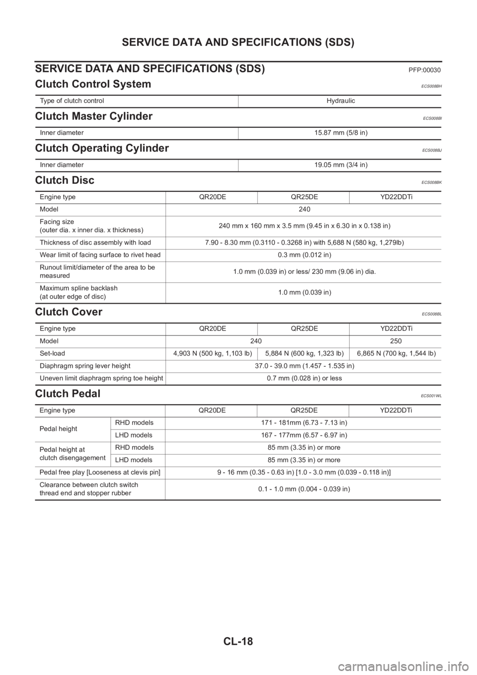
Type of clutch controlHydraulic
Inner diameter15.87 mm (5/8 in)
Inner diameter19.05 mm (3/4 in)
Engine type QR20DE QR25DE YD22DDTi
Model240
Facing size
(outer dia. x inner dia. x thickness)240 mm x 160 mm x 3.5 mm (9.45 in x 6.30 in x 0.138 in)
Thickness of disc assembly with load 7.90 - 8.30 mm (0.3110 - 0.3268 in) with 5,688 N (580 kg, 1,279lb)
Wear limit of facing surface to rivet head 0.3 mm (0.012 in)
Runout limit/diameter of the area to be
measured1.0 mm (0.039 in) or less/ 230 mm (9.06 in) dia.
Maximum spline backlash
(at outer edge of disc)1.0 mm (0.039 in)
Engine type QR20DE QR25DE YD22DDTi
Model 240<0003000300030003000300030003000300030003000300030003000300030003000300030003000300030003000300030003000300030003000300030003000300030003000300030003000300030003000300030003000300030003000300030003000300
030003000300030003[ 250
Set-load 4,903 N (500 kg, 1,103 lb) 5,884 N (600 kg, 1,323 lb) 6,865 N (700 kg, 1,544 lb)
Diaphragm spring lever height 37.0 - 39.0 mm (1.457 - 1.535 in)
Uneven limit diaphragm spring toe height 0.7 mm (0.028 in) or less
Engine type QR20DE QR25DE YD22DDTi
Pedal height RHD models 171 - 181mm (6.73 - 7.13 in)
LHD models 167 - 177mm (6.57 - 6.97 in)
Pedal height at
clutch disengagement RHD models 85 mm (3.35 in) or more
LHD models 85 mm (3.35 in) or more
Pedal free play [Looseness at clevis pin] 9 - 16 mm (0.35 - 0.63 in) [1.0 - 3.0 mm (0.039 - 0.118 in)]
Clearance between clutch switch
thread end and stopper rubber 0.1 - 1.0 mm (0.004 - 0.039 in)
Page 1987 of 3833
SIDE OIL SEAL
MT-11
D
E
F
G
H
I
J
K
L
MA
B
MT
SIDE OIL SEALPFP:32113
Removal and InstallationECS008BT
REMOVAL
●Clutch housing side oil seal used on 4WD vehicles is attached to the transfer. Be sure to replace it
when transfer is removed.
1. Remove the drive shaft from the transaxle.
2. Remove oil seal with flat tip screwdriver.
CAUTION:
Be careful not to damage the case surface when removing
the oil seal.
INSTALLATION
1. Using a drift (special service tool), drive the oil seal straight until
it protrudes from the case end equal to dimension A shown in
the figure.
CAUTION:
●When installing oil seals, apply multi-purpose grease to oil seal lips.
●Oil seals are not reusable. Never reuse them.
2. Install all parts in reverse order of removal and check oil level after installation.
SCIA0824E
Dimension "A":
Within 0.5 mm (0.020 in) of flush with the case.
Drift to be used:
Transaxle case side: ST30720000
Clutch housing side: ST30720000
SCIA0352E
Page 1991 of 3833

TRANSAXLE ASSEMBLY
MT-15
D
E
F
G
H
I
J
K
L
MA
B
MT
TRANSAXLE ASSEMBLYPFP:32010
Removal and InstallationECS008BX
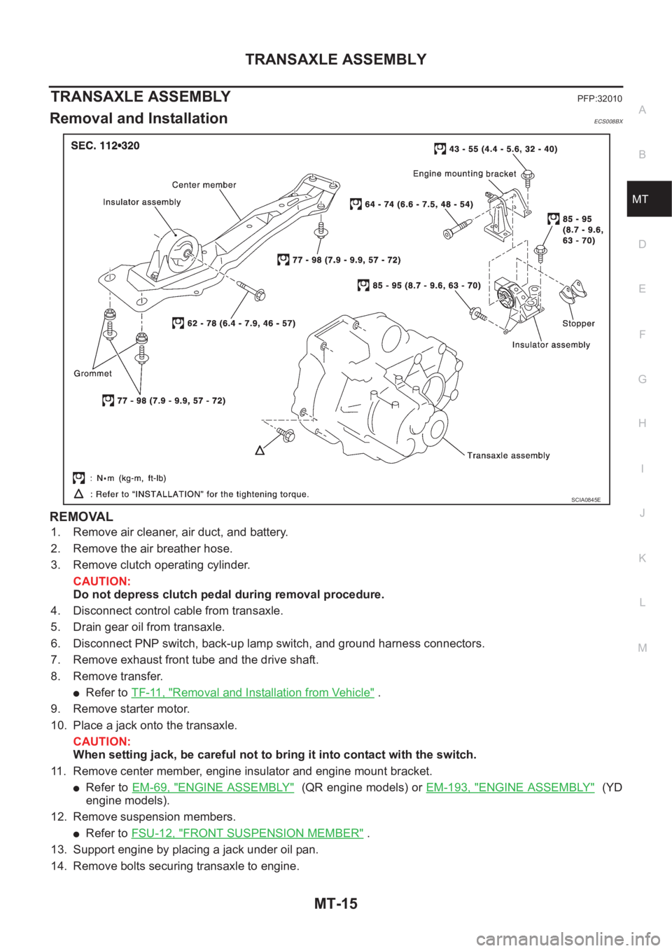
REMOVAL
1. Remove air cleaner, air duct, and battery.
2. Remove the air breather hose.
3. Remove clutch operating cylinder.
CAUTION:
Do not depress clutch pedal during removal procedure.
4. Disconnect control cable from transaxle.
5. Drain gear oil from transaxle.
6. Disconnect PNP switch, back-up lamp switch, and ground harness connectors.
7. Remove exhaust front tube and the drive shaft.
8. Remove transfer.
●Refer to TF-11, "Removal and Installation from Vehicle" .
9. Remove starter motor.
10. Place a jack onto the transaxle.
CAUTION:
When setting jack, be careful not to bring it into contact with the switch.
11. Remove center member, engine insulator and engine mount bracket.
●Refer to EM-69, "ENGINE ASSEMBLY" (QR engine models) or EM-193, "ENGINE ASSEMBLY" (YD
engine models).
12. Remove suspension members.
●Refer to FSU-12, "FRONT SUSPENSION MEMBER" .
13. Support engine by placing a jack under oil pan.
14. Remove bolts securing transaxle to engine.
SCIA0845E
Page 1992 of 3833
MT-16
TRANSAXLE ASSEMBLY
15. Remove transaxle from vehicle.
INSTALLATION
Paying attention to the following items, install in the reverse order of removal.
●When installing the transaxle to the engine, tighten to the specified torque.
CAUTION:
When installing transaxle, be careful not to bring transaxle input shaft into contact with the clutch
cover.
QR engine models:
*: Tightening the bolt for 4WD models.
YD engine models:
●After installation, check oil level, and look for leaks and loose
mechanisms.
MTD0062D
Bolt No. 1 2 3* 4 5 6
Quantity 2 1 1 2 2 2
“ ” mm (in)40
(1.57)75
(2.95)45
(1.77)40
(1.57)30
(1.18)40
(1.57)
Tightening torque
N·m (kg - m, ft- lb)69.6 - 79.4
(7.1 - 8.1, 52 - 58)39.2 - 46.1
(4.0 - 4.7, 29 - 34)30.4 - 40.2
(3.1 - 4.1,
23 - 29)
Bolt No. 1 2 3 4 5 6
Quantity 2 2 1 1 3 1
“ ” mm (in)55
(2.17)70
(2.76)120
(4.72)45
(1.77)40
(1.57)35
(1.38)
Tightening torque
N·m (kg - m, ft- lb)40 - 49
(4.0 - 5.0, 29 - 36)31 - 36
(3.1 - 3.7, 23 - 26)
SCIA0353E
SCIA0748E
Page 1993 of 3833
TRANSAXLE ASSEMBLY
MT-17
D
E
F
G
H
I
J
K
L
MA
B
MT
Component Parts (RS5F51A)ECS008BY
CASE AND HOUSING COMPONENTS
1. Clutch housing 2. Input shaft oil seal 3. Oil channel
4. Magnet 5. Differential oil seal 6. Ball pin
7. Washer 8. Transaxle case 9. Welch plug
10. Bore plug 11. Differential oil seal 12. Park/Neutral position switch
13. Oil gutter 14. Back-up lamp switch 15. Air breather tube
16. Baffle plate 17. Filler plug 18. Gasket
19. Drain plug 20. Gasket
SCIA1112E