2001 NISSAN X-TRAIL ATC-2
[x] Cancel search: ATC-2Page 3302 of 3833
ATC-26
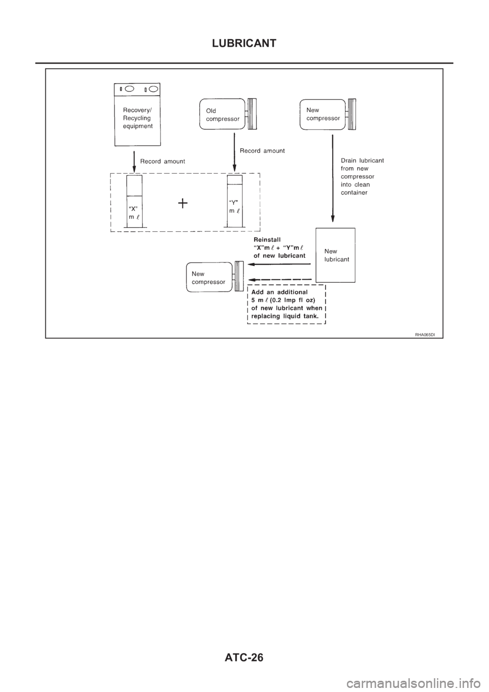
LUBRICANT
RHA065DI
Page 3303 of 3833
AIR CONDITIONER CONTROL
ATC-27
C
D
E
F
G
H
I
K
L
MA
B
AT C
AIR CONDITIONER CONTROLPFP:27500
Overview Air Conditioner LAN Control SystemEJS000TI
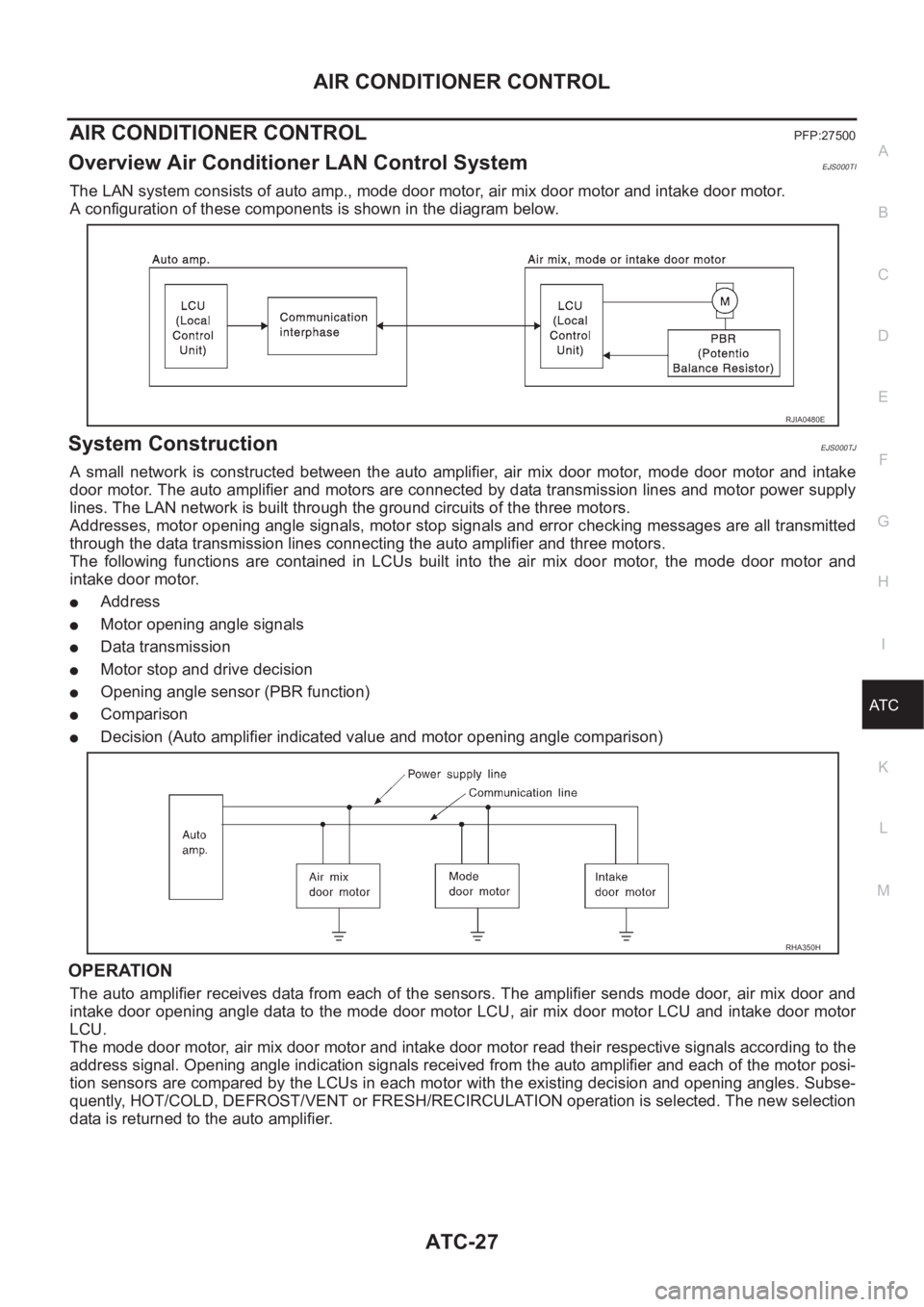
The LAN system consists of auto amp., mode door motor, air mix door motor and intake door motor.
A configuration of these components is shown in the diagram below.
System ConstructionEJS000TJ
A small network is constructed between the auto amplifier, air mix door motor, mode door motor and intake
door motor. The auto amplifier and motors are connected by data transmission lines and motor power supply
lines. The LAN network is built through the ground circuits of the three motors.
Addresses, motor opening angle signals, motor stop signals and error checking messages are all transmitted
through the data transmission lines connecting the auto amplifier and three motors.
The following functions are contained in LCUs built into the air mix door motor, the mode door motor and
intake door motor.
●Address
●Motor opening angle signals
●Data transmission
●Motor stop and drive decision
●Opening angle sensor (PBR function)
●Comparison
●Decision (Auto amplifier indicated value and motor opening angle comparison)
OPERATION
The auto amplifier receives data from each of the sensors. The amplifier sends mode door, air mix door and
intake door opening angle data to the mode door motor LCU, air mix door motor LCU and intake door motor
LCU.
The mode door motor, air mix door motor and intake door motor read their respective signals according to the
address signal. Opening angle indication signals received from the auto amplifier and each of the motor posi-
tion sensors are compared by the LCUs in each motor with the existing decision and opening angles. Subse-
quently, HOT/COLD, DEFROST/VENT or FRESH/RECIRCULATION operation is selected. The new selection
data is returned to the auto amplifier.
RJIA0480E
RHA350H
Page 3304 of 3833
ATC-28
AIR CONDITIONER CONTROL
TRANSMISSION DATA AND TRANSMISSION ORDER
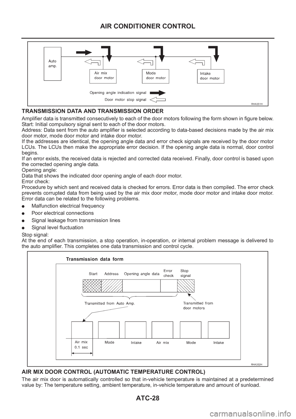
Amplifier data is transmitted consecutively to each of the door motors following the form shown in figure below.
Start: Initial compulsory signal sent to each of the door motors.
Address: Data sent from the auto amplifier is selected according to data-based decisions made by the air mix
door motor, mode door motor and intake door motor.
If the addresses are identical, the opening angle data and error check signals are received by the door motor
LCUs. The LCUs then make the appropriate error decision. If the opening angle data is normal, door control
begins.
If an error exists, the received data is rejected and corrected data received. Finally, door control is based upon
the corrected opening angle data.
Opening angle:
Data that shows the indicated door opening angle of each door motor.
Error check:
Procedure by which sent and received data is checked for errors. Error data is then compiled. The error check
prevents corrupted data from being used by the air mix door motor, mode door motor and intake door motor.
Error data can be related to the following problems.
●Malfunction electrical frequency
●Poor electrical connections
●Signal leakage from transmission lines
●Signal level fluctuation
St op s ign al :
At the end of each transmission, a stop operation, in-operation, or internal problem message is delivered to
the auto amplifier. This completes one data transmission and control cycle.
AIR MIX DOOR CONTROL (AUTOMATIC TEMPERATURE CONTROL)
The air mix door is automatically controlled so that in-vehicle temperature is maintained at a predetermined
value by: The temperature setting, ambient temperature, in-vehicle temperature and amount of sunload.
RHA351H
RHA352H
Page 3305 of 3833
AIR CONDITIONER CONTROL
ATC-29
C
D
E
F
G
H
I
K
L
MA
B
AT C
FAN SPEED CONTROL
Blower speed is automatically controlled based on temperature setting, ambient temperature, in-vehicle tem-
perature, intake temperature, amount of sunload and air mix door position.
With FAN switch set to AUTO, the blower motor starts to gradually increase air flow volume.
When engine coolant temperature is low, the blower motor operation is delayed to prevent cool air from flow-
ing.
INTAKE DOOR CONTROL
The intake doors are automatically controlled by: The temperature setting, ambient temperature, in-vehicle
temperature, intake temperature, amount of sunload and ON-OFF operation of the compressor.
OUTLET DOOR CONTROL
The outlet door is automatically controlled by: The temperature setting, ambient temperature, in-vehicle tem-
perature, intake temperature and amount of sunload.
MAGNET CLUTCH CONTROL
The ECM controls compressor operation using input signals from the throttle position sensor and auto ampli-
fier.
SELF-DIAGNOSTIC SYSTEM
The self-diagnostic system is built into the auto amplifier (LCU) to quickly locate the cause of malfunctions.
Overview of Control systemEJS000TK
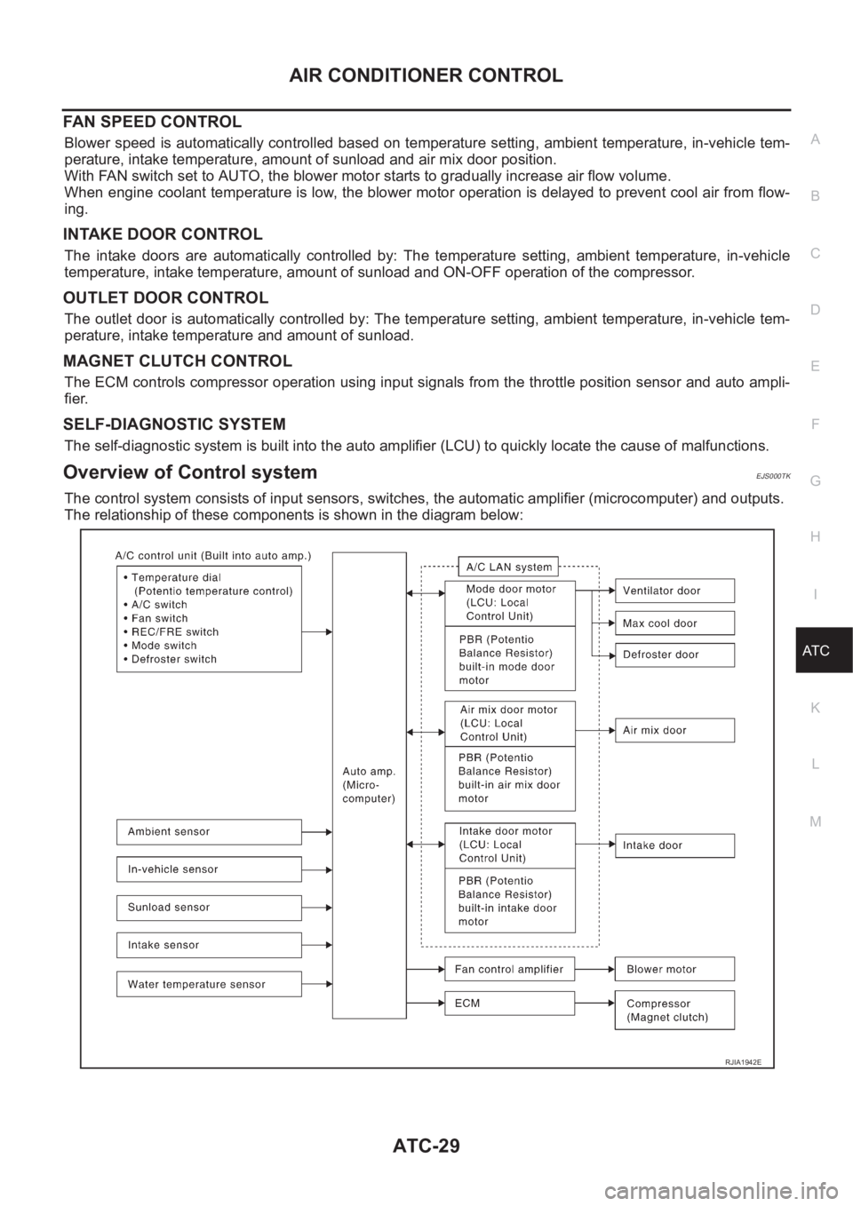
The control system consists of input sensors, switches, the automatic amplifier (microcomputer) and outputs.
The relationship of these components is shown in the diagram below:
RJIA1942E
Page 3406 of 3833
ATC-130
REFRIGERANT LINES
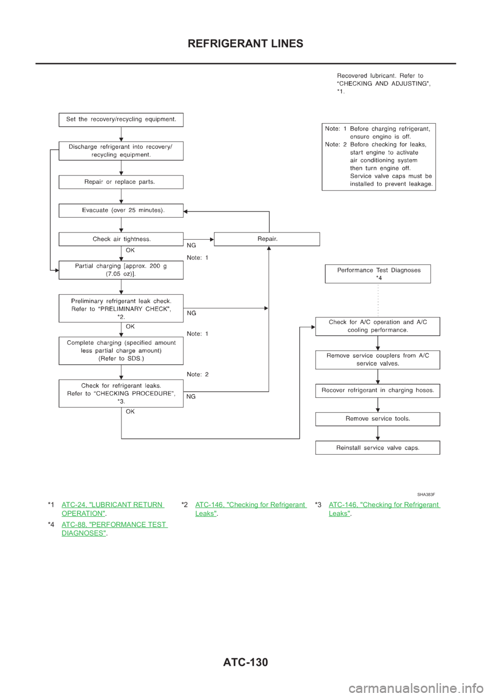
*1ATC-24, "LUBRICANT RETURN
OPERATION".*2AT C - 1 4 6 , "
Checking for Refrigerant
Leaks".*3ATC-146, "
Checking for Refrigerant
Leaks".
*4ATC-88, "
PERFORMANCE TEST
DIAGNOSES".
SHA383F
Page 3826 of 3833
IDX-2
ALPHABETICAL INDEX
Numerics
4WD mode switch ................................... TF-54
,TF-57
4WD shift indicator lamp .................................... TF-55
4WD solenoid valve ................................ TF-49,TF-52
4WD warning lamp TF-40,TF-55,TF-56,TF-57,TF-58
A
A/C air flow ......................................... ATC-31
,MTC-5
A/C component layout ..................................... ATC-23
A/C compressor clutch removal and installation ...........
ATC-135
A/C compressor precaution ............................... ATC-9
A/C compressor special service tool ................ ATC-14
A/C diagnostic work flow (auto A/C) ................ ATC-33
A/C HFC134a (R134a) system precaution ........ ATC-4
A/C HFC134a (R134a) system service procedure .......
ATC-129
A/C HFC134a (R134a) system service tools ... ATC-15
A/C HFC134a system service equipment precaution ...
ATC-10
A/C lubricant (R134a) ...................................... ATC-24
A/C operational check ......................... ATC-54,MTC-7
A/C performance test diagnoses ..................... ATC-88
A/C reray .......................................................... ATC-84
A/C self-diagnoses (auto A/C) ......................... ATC-46
A/C system description (auto A/C) ................... ATC-27
A/C trouble diagnoses (auto A/C) ....... ATC-33,MTC-3
A/C, A - Wiring diagram ................................... ATC-38
A/CCUT - Wiring diagram .............................. EC-1572
A/T - Wiring diagram - AT - FTS ...................... AT-118
A/T - Wiring diagram - AT - MAIN .................... AT-350
A/T - Wiring diagram - AT - PNP/SW ............... AT-112
A/T - Wiring diagram - AT - VSS A/T . AT-124,AT-355
A/T fluid checking .................................. AT-13,MA-36
A/T fluid replacement ............................. AT-13,MA-36
A/T fluid temperature sensor ........................... AT-121
A/T IND - Wiring diagram .................................... DI-57
A/T indicator ........................................................ DI-57
A/T shift lock system ........................................ AT-406
A/T shift lock system - Wiring diagram ............ AT-407
A/T trouble diagnoses .......................... AT-56,AT-258
A/T Wiring diagram - AT - ENG SS ... AT-128,AT-393
A/T Wiring diagram AT - 1ST ........................... AT-134
A/T Wiring diagram AT - 2ND .......................... AT-140
A/T Wiring diagram AT - 3RD .......................... AT-146
A/T Wiring diagram AT - 4TH .......................... AT-152
A/T Wiring diagram AT - BA/FTS ....... AT-195,AT-388
A/T Wiring diagram AT - CAN ............ AT-191,AT-404
A/T Wiring diagram AT - LPSV .......... AT-165,AT-398
A/T Wiring diagram AT - OVRCSV .... AT-187,AT-378
A/T Wiring diagram AT - SSV/A ......... AT-172,AT-369
A/T Wiring diagram AT - SSV/B ......... AT-177,AT-374
A/T Wiring diagram AT - TCV ............ AT-160,AT-383
A/T Wiring diagram AT - TPS ............ AT-182,AT-364
A/T Wiring diagrawm AT - VSSMTR .. AT-201,AT-360
ABS - Wiring diagram ..................................... BRC-12
Absolute pressure sensor .............................. EC-1494
Accelerator control system ............................... ACC-2
Accelerator pedal position (APP) sensor ........ EC-355,
EC-361
,EC-373,EC-631,EC-637,EC-651,EC-893,
EC-1222
,EC-1460
Accelerator pedal released position learning . EC-1404
Accelerator pedal released position switch .... EC-1531
Actuator relay ..................................................... TF-52
Aiming adjustment ............................................... LT-4
Air bag .............................................................. SRS-3
Air bag disposal .............................................. SRS-41
Air bleeding (hydraulic clutch) .............................. CL-8
Air bleeding for brake system ............................ BR-10
Air cleaner and air duct(QR20DE•QR25DE) .... EM-14
Air cleaner and air duct(YD22DDTi) ............... EM-120
Air cleaner filter replacement(QR20DE•QR25DE) ........
MA-22
Air cleaner filter replacement(YD22DDTi) ......... MA-32
Air cleaner filter(QR20DE•QR25DE) ................ EM-14
Air cleaner filter(YD22DDTi) ........................... EM-120
Air conditioner cut control .... EC-36,EC-446,EC-768,
EC-1132
,EC-1401
Air flow meter - See Mass air flow sensor ....... EC-138,
EC-516
,EC-870,EC-999,EC-1202
Air mix door control linkage adjustment ......... ATC-66,
ATC-125
,MTC-10,MTC-28
Air mix. door motor ......................... ATC-64,ATC-125
Air spoiler, rear ................................................... EI-21
Alternator ........................................................... SC-12
Ambient sensor ............. ATC-100,ATC-102,ATC-112
Angular tightening application(QR20DE•QR25DE) ......
EM-5
Angular tightening application(YD22DDTi) ..... EM-110
Antenna - See Power antenna ........................... AV-16
APPS - Wiring diagram ... EC-895,EC-1225,EC-1462
APPS1 - Wiring diagram ................... EC-357,EC-633
APPS2 - Wiring diagram ................... EC-363,EC-640
APPS3 - Wiring diagram ................... EC-375,EC-653
APRSW - Wiring diagram .............................. EC-1533
Audio .................................................................... AV-3
Auto air conditioner - Wiring diagram ............. ATC-38
Automatic amplifier ........................... ATC-44,ATC-57
Automatic transmission fluid replacement ....... MA-35,
MA-37
Axle ................................................................... MA-41
B
Back door ........................................................... BL-71
Back door trim ..................................................... EI-25
Back door window .............................................. GW-8
Back window ...................................................... GW-8
BACK/L - Wiring diagram ................................... LT-28
Back-up lamp .......................................... LT-28,LT-42
Back-up lamp switch (M/T) ............................... MT-12
Basic inspection ... EC-73,EC-465,EC-805,EC-1152,
EC-1412
Battery ................................................................. SC-3
Baulk ring (M/T) .................................... MT-18,MT-23
Blower motor ..... ATC-70,ATC-77,ATC-118,MTC-14,
Page 3830 of 3833
IDX-6
ALPHABETICAL INDEX
EC-181,EC-536,EC-862,EC-901,EC-908,EC-917,
EC-1231
HO2S2 - Wiring diagram .... EC-187,EC-195,EC-310,
EC-318
,EC-923,EC-930,EC-1038,EC-1045
HO2S2H - Wiring diagram ................. EC-135,EC-867
Hood .................................................................... BL-4
Horn ................................................................. WW-23
HORN - Wiring diagram ................................... WW-23
How to erase DTC ......................................... EC-1406
How to erase DTC for OBD system .... EC-56,EC-455,
EC-788
,EC-1142
I
IATS - Wiring diagram ....................... EC-146
,EC-878
IATSEN - Wiring diagram ................ EC-668,EC-1317
Identification ..................................................... ATC-12
Idle air volume learning ........ EC-39,EC-450,EC-772,
EC-1137
Idle speed EC-73,EC-465,EC-805,EC-1152,EC-1412
IGN/SG - Wiring diagram ................. EC-380,EC-1075
Ignition coil ........ EC-379,EC-683,EC-1074,EC-1331
Ignition coil(QR20DE•QR25DE) ....................... EM-29
Ignition control system ..... EC-379,EC-683,EC-1074,
EC-1331
Ignition timing ........ EC-73,EC-465,EC-805,EC-1152
IGNSYS - Wiring diagram ................ EC-684,EC-1332
ILL - Wiring diagram ........................................... LT-45
Illumination .......................................................... LT-45
In vehicle sensor ........... ATC-102,ATC-104,ATC-113
INJECT - Wiring diagram . EC-389,EC-710,EC-1084,
EC-1358
,EC-1475
Injection nozzle(YD22DDTi) ........................... EM-144
Injector .............. EC-388,EC-709,EC-1083,EC-1357
Input shaft (FF M/T) .............................. MT-18,MT-23
Instrument panel ................................................... IP-3
INT/L - Wiring diagram ........................................ LT-65
Intake air temperature sensor ........... EC-144,EC-160,
EC-667
,EC-876,EC-1316
Intake door control linkage adjustment ............ ATC-69
Intake door motor ATC-68,ATC-119,MTC-11,MTC-23
Intake manifold(QR20DE•QR25DE) ................. EM-16
Intake manifold(YD22DDTi) ............................ EM-123
Intake sensor ................................ ATC-108,ATC-115
Intake valve timing control . EC-125,EC-699,EC-857,
EC-1347
Intake valve timing control solenoid valve ...... EC-271,
EC-699
,EC-1005,EC-1347
Interior ....................... EI-23,EI-25,EI-26,EI-28,EI-29
Interior lamp ........................................................ LT-55
Interior lamp on-off control ...................... LT-55,LT-56
ISO 15031-5 Mode 1 - 9 ...................... EC-44,EC-777
IVC - Wiring diagram ....................... EC-273,EC-1007
IVC/V - Wiring diagram .................... EC-701,EC-1349
J
Joint connector (J/C) ............................. PG-70
,PG-74
K
Keyless entry system - See Multi-remote control system
BL-55
Knock sensor (KS) EC-222,EC-546,EC-951,EC-1235
KS - Wiring diagram ........... EC-224,EC-548,EC-953,
EC-1237
L
LAN system circuit .......................................... ATC-59
License lamp ...................................................... LT-30
Line pressure solenoid valve ........................... AT-156
Line pressure test (A/T) ....................... AT-67,AT-268
Liquid gasket application(QR20DE•QR25DE) ... EM-6,
EM-111
,LU-3,LU-15,CO-3,CO-23
LOAD - Wiring diagram .... EC-416,EC-737,EC-1103,
EC-1377
Location of electrical units ................................ PG-63
Lock, door ............................................... BL-65,BL-68
Lubricant (R134a) A/C ........................ ATC-5,ATC-24
Lubrication circuit (engine)(QR20DE•QR25DE) .. LU-5
Lubrication circuit (engine)(YD22DDTi) ............. LU-17
Lubrication oil A/C ......................................... ATC-150
Lubrication-locks, hinges and hood latches ...... MA-41
M
M/T major overhaul ............................... MT-26
,MT-35
M/T oil replacement .......................................... MT-10
M/T removal and installation ............................. MT-15
MAFS - Wiring diagram ..... EC-140,EC-519,EC-872,
EC-1001
,EC-1205,EC-1453
Magnet clutch ................................. ATC-78,ATC-135
MAIN - Wiring diagram ...... EC-116,EC-507,EC-848,
EC-1193
,EC-1443
Mainshaft (M/T) ..................................... MT-18,MT-23
Maintenance (engine)(QR20DE•QR25DE) ....... MA-19
Maintenance (engine)(YD22DDTi) ................... MA-26
Malfunction indicator (MI) .. EC-263,EC-576,EC-991,
EC-1265
,EC-1407
Malfunction indicator lamp (MIL) ........ EC-58,EC-457,
EC-790
,EC-1144
Mass air flow sensor (MAFS) ........... EC-138,EC-516,
EC-870
,EC-999,EC-1202,EC-1451
Master cylinder (brake) ...................................... BR-13
Master cylinder (clutch) ........................................ CL-9
METER - Wiring diagram ........................... DI-8,DI-28
MIL - Wiring diagram ......... EC-264,EC-577,EC-992,
EC-1266
MIL/DL - Wiring diagram ................................ EC-1573
MIRROR - Wiring diagram ............................... GW-50
Mirror defogger ................................................ GW-15
Mirror, door ...................................................... GW-49
Mirror, out side ................................................. GW-49
Misfire ............................................... EC-217,EC-946
Mode door control linkage adjustment ........... ATC-64,
ATC-124
,MTC-9,MTC-27
Mode door motor ............................ ATC-62,ATC-124