2001 NISSAN X-TRAIL oil pressure
[x] Cancel search: oil pressurePage 2697 of 3833
REAR FINAL DRIVE ASSEMBLY
RFD-21
C
E
F
G
H
I
J
K
L
MA
B
RFD
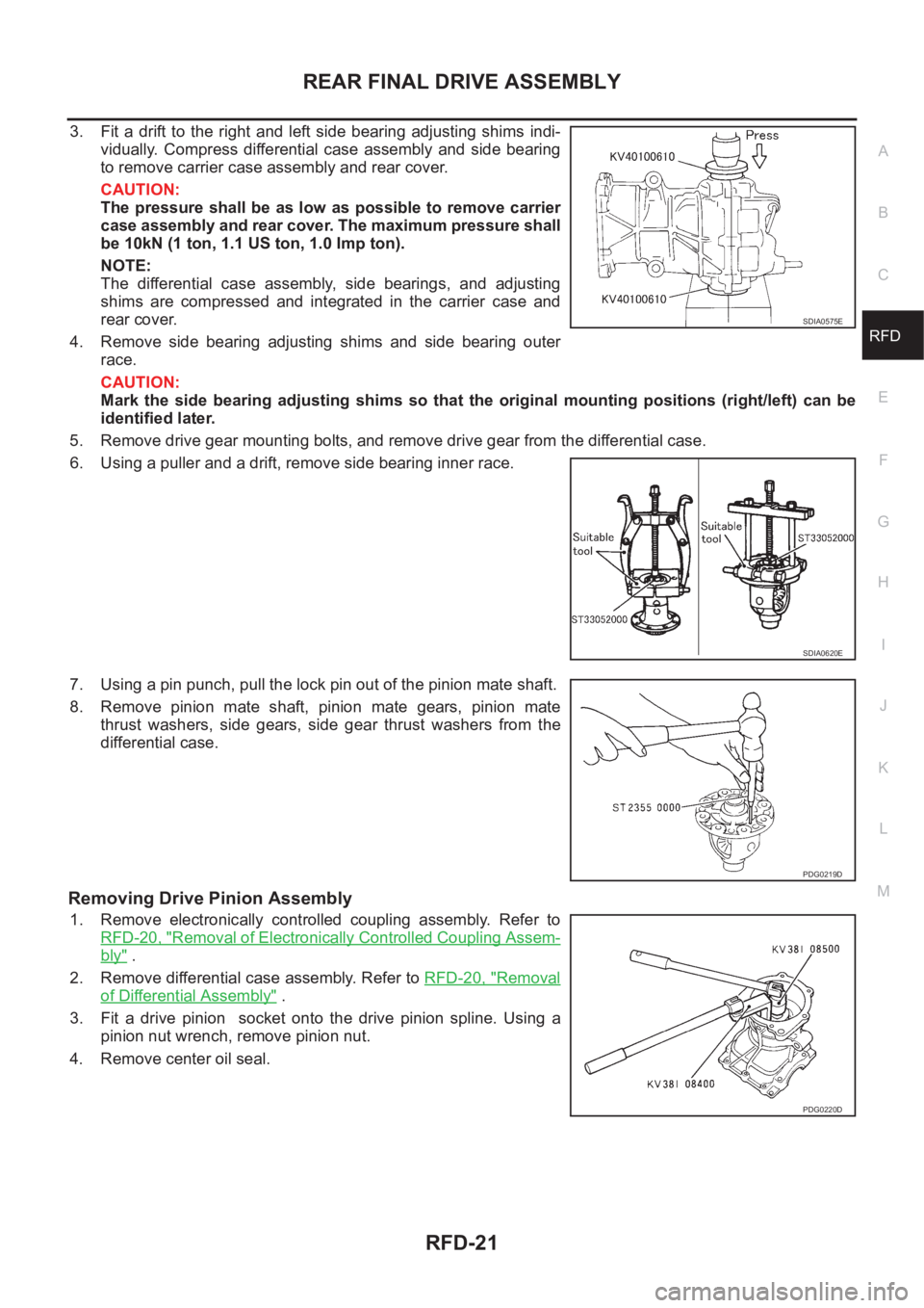
3. Fit a drift to the right and left side bearing adjusting shims indi-
vidually. Compress differential case assembly and side bearing
to remove carrier case assembly and rear cover.
CAUTION:
The pressure shall be as low as possible to remove carrier
case assembly and rear cover. The maximum pressure shall
be 10kN (1 ton, 1.1 US ton, 1.0 Imp ton).
NOTE:
The differential case assembly, side bearings, and adjusting
shims are compressed and integrated in the carrier case and
rear cover.
4. Remove side bearing adjusting shims and side bearing outer
race.
CAUTION:
Mark the side bearing adjusting shims so that the original mounting positions (right/left) can be
identified later.
5. Remove drive gear mounting bolts, and remove drive gear from the differential case.
6. Using a puller and a drift, remove side bearing inner race.
7. Using a pin punch, pull the lock pin out of the pinion mate shaft.
8. Remove pinion mate shaft, pinion mate gears, pinion mate
thrust washers, side gears, side gear thrust washers from the
differential case.
Removing Drive Pinion Assembly
1. Remove electronically controlled coupling assembly. Refer to
RFD-20, "
Removal of Electronically Controlled Coupling Assem-
bly" .
2. Remove differential case assembly. Refer to RFD-20, "
Removal
of Differential Assembly" .
3. Fit a drive pinion socket onto the drive pinion spline. Using a
pinion nut wrench, remove pinion nut.
4. Remove center oil seal.
SDIA0575E
SDIA0620E
PDG0219D
PDG0220D
Page 2703 of 3833
REAR FINAL DRIVE ASSEMBLY
RFD-27
C
E
F
G
H
I
J
K
L
MA
B
RFD
9. Apply differential oil to the side bearings, and assemble new side bearing adjusting shims (2 pieces for
one side) with the same thickness as the ones installed prior to disassembly or re-install the old ones, with
a side bearing outer race to the differential case.
If the side bearing adjusting shims have been already selected, use them.
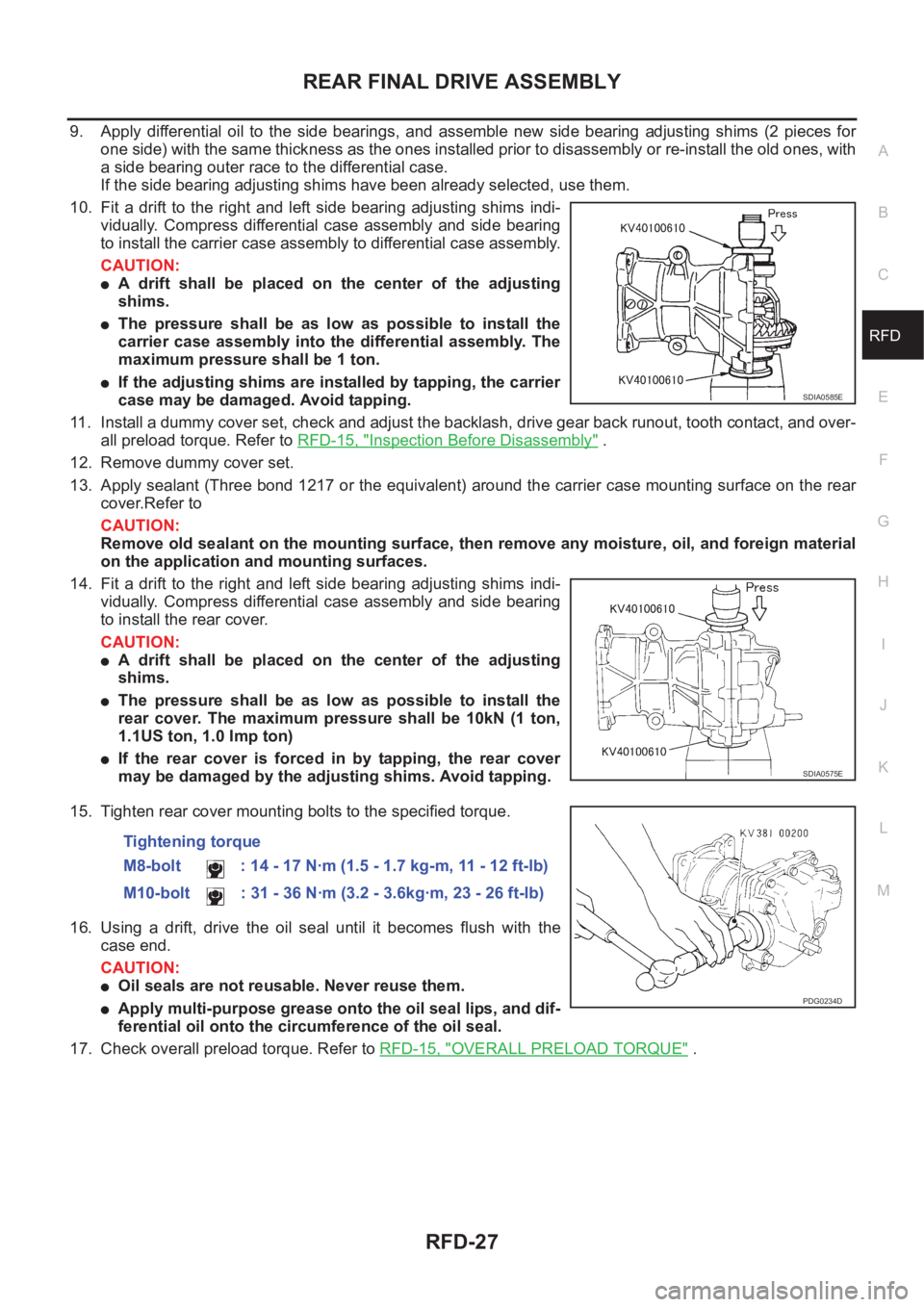
10. Fit a drift to the right and left side bearing adjusting shims indi-
vidually. Compress differential case assembly and side bearing
to install the carrier case assembly to differential case assembly.
CAUTION:
●A drift shall be placed on the center of the adjusting
shims.
●The pressure shall be as low as possible to install the
carrier case assembly into the differential assembly. The
maximum pressure shall be 1 ton.
●If the adjusting shims are installed by tapping, the carrier
case may be damaged. Avoid tapping.
11. Install a dummy cover set, check and adjust the backlash, drive gear back runout, tooth contact, and over-
all preload torque. Refer to RFD-15, "
Inspection Before Disassembly" .
12. Remove dummy cover set.
13. Apply sealant (Three bond 1217 or the equivalent) around the carrier case mounting surface on the rear
cover.Refer to
CAUTION:
Remove old sealant on the mounting surface, then remove any moisture, oil, and foreign material
on the application and mounting surfaces.
14. Fit a drift to the right and left side bearing adjusting shims indi-
vidually. Compress differential case assembly and side bearing
to install the rear cover.
CAUTION:
●A drift shall be placed on the center of the adjusting
shims.
●The pressure shall be as low as possible to install the
rear cover. The maximum pressure shall be 10kN (1 ton,
1.1US ton, 1.0 Imp ton)
●If the rear cover is forced in by tapping, the rear cover
may be damaged by the adjusting shims. Avoid tapping.
15. Tighten rear cover mounting bolts to the specified torque.
16. Using a drift, drive the oil seal until it becomes flush with the
case end.
CAUTION:
●Oil seals are not reusable. Never reuse them.
●Apply multi-purpose grease onto the oil seal lips, and dif-
ferential oil onto the circumference of the oil seal.
17. Check overall preload torque. Refer to RFD-15, "
OVERALL PRELOAD TORQUE" .
SDIA0585E
SDIA0575E
Tightening torque
M8-bolt : 14 - 17 N·m (1.5 - 1.7 kg-m, 11 - 12 ft-lb)
M10-bolt : 31 - 36 N·m (3.2 - 3.6kg·m, 23 - 26 ft-lb)
PDG0234D
Page 2712 of 3833
FSU-6
FRONT SUSPENSION ASSEMBLY
On-Vehicle Inspection and Service
EES00072
LOOSENESS, BACKLASH AND DAMAGE OF MOUNTING PARTS AND CONNECTIONS
Lift vehicle and inspect the following:
●Check mounting point of each component for looseness, backlash and damage.
●Check lower ball joint end play.
1. Attach a dial gauge so that the contact rests on the brake caliper.
2. Set front wheels in a straight-ahead position. Do not depress brake pedal.
3. Measure axial endplay by placing an iron pry bar or something similar between transverse link and steer-
ing knuckle.
CAUTION:
Be careful not to damage ball joint boot.
4. If axial endplay is outside the standard, remove transverse link and check lower ball joint.
Wheel AlignmentEES00073
DESCRIPTION
●Measure wheel alignment under unladen conditions. “Unladen conditions” means that fuel, coolant, and
lubricant are full. However, spare tire, jack, and hand tools should be unloaded.
PRELIMINARY INSPECTION
1. Check the tires for improper air pressure and wear.
2. Check road wheels for runout.
3. Check wheel bearing axial endplay.
4. Check lower ball joint axial endplay.
5. Check strut operation.
6. Check each mounting point of axle and suspension for looseness and deformation.
7. Check each link and arm for cracks, deformation, and other damage.
8. Check the vehicle posture.
INSPECTION OF CAMBER, CASTER, AND KINGPIN INCLINATION ANGLES
● Camber, caster, and kingpin inclination angles cannot be adjusted.
●Before inspection, mount front wheels onto turning radius gauge. Mount rear wheels onto a stand that has
same height so the vehicle will remain horizontal.
1. Measure camber, caster and kingpin inclination of both right and
left wheels with a suitable alignment gauge.
2. If camber, caster or kingpin inclination is not within specification,
inspect front suspension parts. Replace dam-aged or worn out
parts.
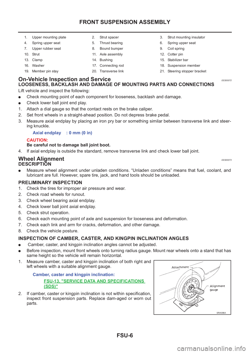
1. Upper mounting plate 2. Strut spacer 3. Strut mounting insulator
4. Spring upper seat 5. Thrust bearing 6. Spring upper seat
7. Upper rubber seat 8. Bound bumper 9. Coil spring
10. Strut 11. Axle assembly 12. Cotter pin
13. Clamp 14. Bushing 15. Stabilizer bar
16. Washer 17. Connecting rod 18. Suspension member
19. Member pin stay 20. Transverse link 21. Steering stopper bracket
Axial endplay : 0 mm (0 in)
Camber, caster and kingpin inclination:
FSU-13, "
SERVICE DATA AND SPECIFICATIONS
(SDS)"
SRA096A
Page 2726 of 3833
RSU-6
REAR SUSPENSION ASSEMBLY
On-Vehicle Inspection and Service
EES0007F
Check axle and suspension parts for excessive play, wear, and damage.
●Move rear wheels (RH/LH) to check abnormal free play.
●Retighten all nuts and bolts to the specified torque.
●Check strut for oil leakage and damage.
Wheel AlignmentEES0007G
DESCRIPTION
●Measure wheel alignment under unladen conditions. “Unladen conditions” means that fuel, coolant, and
lubricant are full. However, spare tire, jack, and hand tools should be unloaded.
PRELIMINARY INSPECTION
1. Check the tires for improper air pressure and wear.
2. Check road wheels for runout.
3. Check wheel bearing axial endplay.
4. Check strut operation.
5. Check each mounting point of axle and suspension for looseness and deformation.
6. Check each link and arm for cracks, deformation, and other damage.
7. Check the vehicle posture.
CAMBER
Camber is preset at factory and cannot be adjusted.
●If the camber is not within specification, inspect and replace any damaged or worn rear suspension parts.
TOE-IN
Measure toe-in using the following procedure.
●Always perform following procedure on a flat surface.
●Make sure that no person is in front of the vehicle before push-
ing it.
1. Bounce rear of vehicle up and down to stabilize the posture.
2. Push the vehicle straight ahead about 5 m (16 ft).
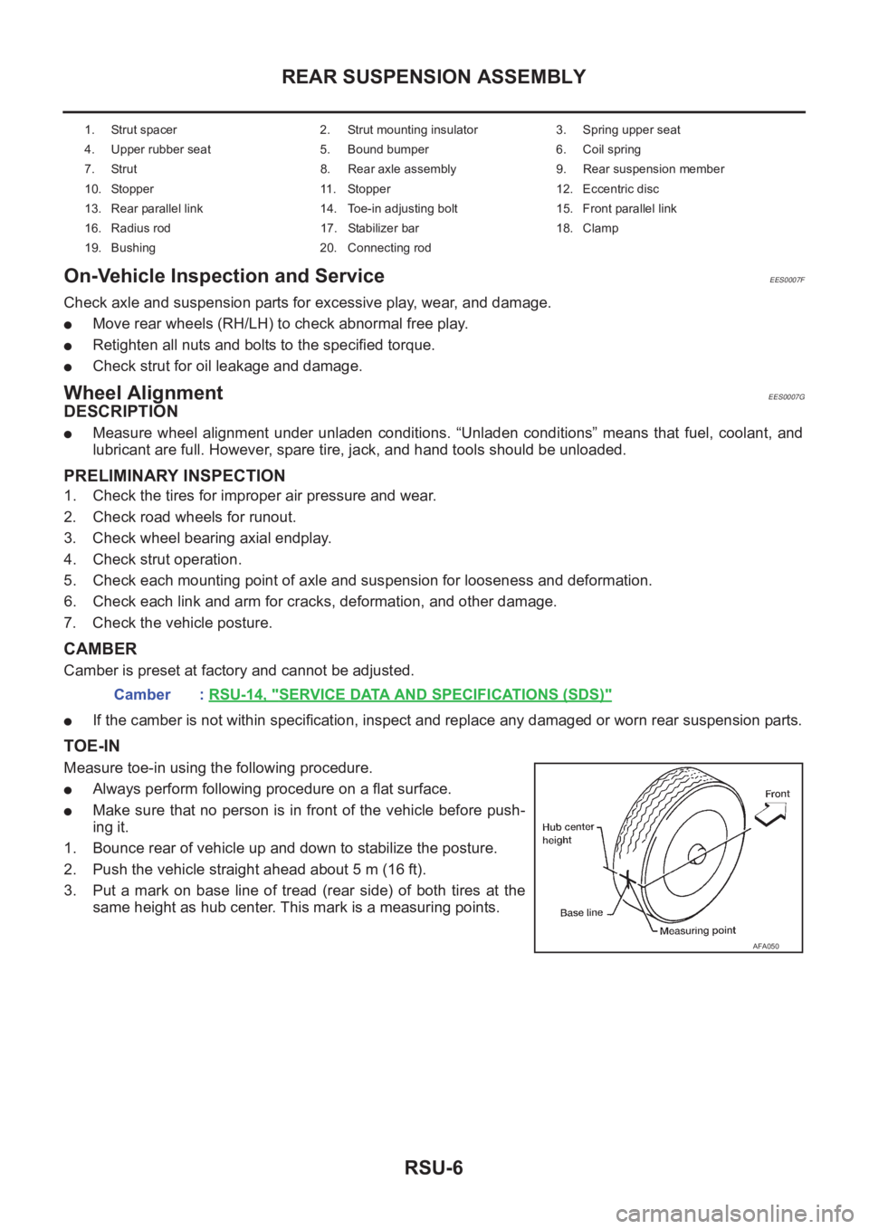
3. Put a mark on base line of tread (rear side) of both tires at the
same height as hub center. This mark is a measuring points.
1. Strut spacer 2. Strut mounting insulator 3. Spring upper seat
4. Upper rubber seat 5. Bound bumper 6. Coil spring
7. Strut 8. Rear axle assembly 9. Rear suspension member
10. Stopper 11. Stopper 12. Eccentric disc
13. Rear parallel link 14. Toe-in adjusting bolt 15. Front parallel link
16. Radius rod 17. Stabilizer bar 18. Clamp
19. Bushing 20. Connecting rod
Camber : RSU-14, "SERVICE DATA AND SPECIFICATIONS (SDS)"
AFA050
Page 2788 of 3833
![NISSAN X-TRAIL 2001 Service Repair Manual BRC-4
[4WD/ABS]
PRECAUTIONS
[4WD/ABS]PRECAUTIONSPFP:00001
Precautions for brake systemEFS001B6
●Recommended fluid is brake fluid “DOT 3 ”or “DOT 4”.
●Never reuse drained brake fluid.
●Be NISSAN X-TRAIL 2001 Service Repair Manual BRC-4
[4WD/ABS]
PRECAUTIONS
[4WD/ABS]PRECAUTIONSPFP:00001
Precautions for brake systemEFS001B6
●Recommended fluid is brake fluid “DOT 3 ”or “DOT 4”.
●Never reuse drained brake fluid.
●Be](/manual-img/5/57405/w960_57405-2787.png)
BRC-4
[4WD/ABS]
PRECAUTIONS
[4WD/ABS]PRECAUTIONSPFP:00001
Precautions for brake systemEFS001B6
●Recommended fluid is brake fluid “DOT 3 ”or “DOT 4”.
●Never reuse drained brake fluid.
●Be careful not to splash brake fluid on painted areas.
●To clean or wash all parts of master cylinder, disc brake caliper and wheel cylinder, use clean brake fluid.
●Never use mineral oils such as gasoline or kerosene. They will ruin rubber parts of the hydraulic system.
●Use flare nut wrench when removing and installing brake tube.
●Always torque brake lines when installing.
●Burnish the brake contact surfaces after refinishing or replacing
drums or rotors, after replacing pads or linings, or if a soft pedal
occurs at very low mileage. Refer to BR-10, "
Brake Burnishing
Procedure" .
●Before working, turn OFF ignition switch. Disconnect connectors
for ABS actuator and control module or battery terminals.
WARNING:
●Clean brake pads and shoes with a waste cloth, then wipe
with a dust collector.
Precautions for brake controlEFS001B7
●If malfunction is indicated by 4WD warning lamp and/or ABS warning lamp, collect necessary information
from customer (what symptoms are present under what conditions). Find out possible causes before start-
ing service. Besides electrical system inspection, check operation of ABS actuator.
●If malfunction is detected, proceed to trouble diagnosis after checking tire pressure and tire wear.
●Stopping distance or steering stability may be deteriorated by the following conditions. Tire size and type
are in improper combination. Brake pads are not Nissan genuine parts.
●Fitting tires of different size on vehicle can be cause of longitudinal vibration. Always use tires of the same
size and brand. Exchange front and rear tires on the following conditions: Longitudinal vibration occurs in
vehicle with tires of the same size and brand. After replacement, perform trouble diagnosis. 1580|None
●4WD/ABS function may have a failure or error under following condition: There is radio, antenna, or
antenna lead-in wire (including wiring) near control module.
●If aftermarket parts (e.g. Car stereo equipment, CD player) have been installed, check electrical har-
nesses for pinches, open, and improper wiring.
SBR820BA
Page 2911 of 3833
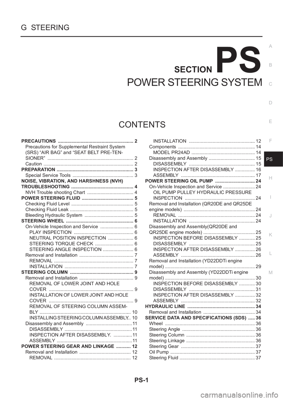
PS-1
POWER STEERING SYSTEM
G STEERING
CONTENTS
C
D
E
F
H
I
J
K
L
M
SECTION
A
B
PS
POWER STEERING SYSTEM
PRECAUTIONS .......................................................... 2
Precautions for Supplemental Restraint System
(SRS) “AIR BAG” and “SEAT BELT PRE-TEN-
SIONER” .................................................................. 2
Caution ..................................................................... 2
PREPARATION ........................................................... 3
Special Service Tools ............................................... 3
NOISE, VIBRATION, AND HARSHNESS (NVH)
TROUBLESHOOTING ................................................ 4
NVH Trouble shooting Chart .................................... 4
POWER STEERING FLUID ........................................ 5
Checking Fluid Level ........................................... ..... 5
Checking Fluid Leak ............................................ ..... 5
Bleeding Hydraulic System ...................................... 5
STEERING WHEEL .................................................... 6
On-Vehicle Inspection and Service .......................... 6
PLAY INSPECTION .............................................. 6
NEUTRAL POSITION INSPECTION .................... 6
STEERING TORQUE CHECK .............................. 6
STEERING ANGLE INSPECTION ........................ 6
Removal and Installation .......................................... 7
REMOVAL ............................................................. 7
INSTALLATION ..................................................... 7
STEERING COLUMN ................................................. 9
Removal and Installation .......................................... 9
REMOVAL OF LOWER JOINT AND HOLE
COVER ................................................................. 9
INSTALLATION OF LOWER JOINT AND HOLE
COVER ................................................................. 9
REMOVAL OF STEERING COLUMN ASSEM-
BLY ...................................................................... 10
INSTALLING STEERING COLUMN ASSEMBLY ... 10
Disassembly and Assembly .................................... 11
DISASSEMBLY .................................................... 11
INSPECTION AFTER DISASSEMBLY. ............... 11
ASSEMBLY .......................................................... 11
POWER STEERING GEAR AND LINKAGE ............ 12
Removal and Installation ........................................ 12
REMOVAL ........................................................... 12INSTALLATION ................................................... 12
Components ........................................................... 14
MODEL PR24AD ................................................. 14
Disassembly and Assembly .................................... 15
DISASSEMBLY ................................................... 15
INSPECTION AFTER DISASSEMBLY ................ 16
ASSEMBLY ......................................................... 17
POWER STEERING OIL PUMP ............................... 24
On-Vehicle Inspection and Service ......................... 24
OIL PUMP PULLEY HYDRAULIC PRESSURE
INSPECTION ...................................................... 24
Removal and Installation (QR20DE and QR25DE
engine models) ....................................................... 24
REMOVAL ........................................................... 24
INSTALLATION ................................................... 24
Disassembly and Assembly(QR20DE and
QR25DE engine models) ........................................ 25
INSPECTION BEFORE DISASSEMBLY ............. 25
DISASSEMBLY ................................................... 25
INSPECTION AFTER DISASSEMBLY ................ 26
ASSEMBLY ......................................................... 26
Removal and Installation (YD22DDTi engine
model) ..................................................................... 29
Disassembly and Assembly (YD22DDTi engine
model) ..................................................................... 30
INSPECTION BEFORE DISASSEMBLY ............. 30
DISASSEMBLY ................................................... 31
INSPECTION AFTER DISASSEMBLY ................ 32
ASSEMBLY ......................................................... 32
HYDRAULIC LINE .................................................
... 34
Removal and Installation ........................................ 34
SERVICE DATA AND SPECIFICATIONS (SDS) ...... 36
Wheel ..................................................................... 36
Steering Angle ........................................................ 36
Steering Column ..................................................... 36
Steering Linkage ..................................................... 36
Steering Gear ......................................................... 37
Oil Pump ................................................................. 37
Steering Fluid .......................................................... 37
Page 2913 of 3833
PREPARATION
PS-3
C
D
E
F
H
I
J
K
L
MA
B
PS
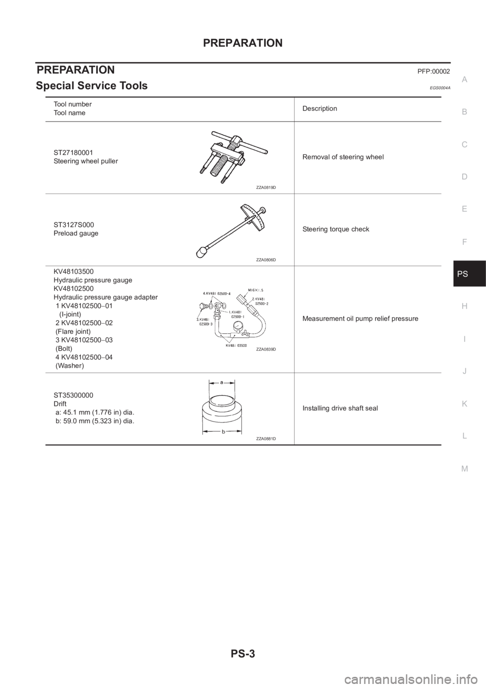
PREPARATIONPFP:00002
Special Service ToolsEGS0004A
Tool number
Tool nameDescription
ST27180001
Steering wheel pullerRemoval of steering wheel
ST3127S000
Preload gaugeSteering torque check
KV48103500
Hydraulic pressure gauge
KV48102500
Hydraulic pressure gauge adapter
1 KV48102500−01
(I-joint)
2 KV48102500−02
(Flare joint)
3 KV48102500−03
(Bolt)
4 KV48102500−04
(Washer)Measurement oil pump relief pressure
ST35300000
Drift
a: 45.1 mm (1.776 in) dia.
b: 59.0 mm (5.323 in) dia.Installing drive shaft seal
ZZA0819D
ZZA0806D
ZZA0839D
ZZA0881D
Page 2916 of 3833
PS-6
STEERING WHEEL
STEERING WHEEL
PFP:48430
On-Vehicle Inspection and ServiceEGS0004E
PLAY INSPECTION
1. Turn steering wheel to straight-ahead position. Start engine and lightly turn steering wheel clockwise and
counter clockwise until front wheels start moving. Measure travel to starting point on circumference of
steering wheel.
2. If play is outside specifications, check following parts for proper installation: steering gear assembly, front
suspension, axles, and steering column
●Check steering wheel for vertical, horizontal, or axial play.
●Lift vehicle and check steering gear mounting bolts and nuts for looseness.
NEUTRAL POSITION INSPECTION
●After the wheel alignment inspection, carry out the neutral position inspection. Refer to FSU-6, "Wheel
Alignment" .
●Before removing steering wheel, check steering gear neutral position.
1. Set vehicle to straight-ahead position, and check that steering wheel is in neutral position.
2. If it is not in neutral position, remove steering wheel, and install again in properly.
3. If it is not adjusted within two teeth from center of gear, loosen tie rod lock nut. Then turn it to opposite
direction to adjust until amount of left and right becomes equal.
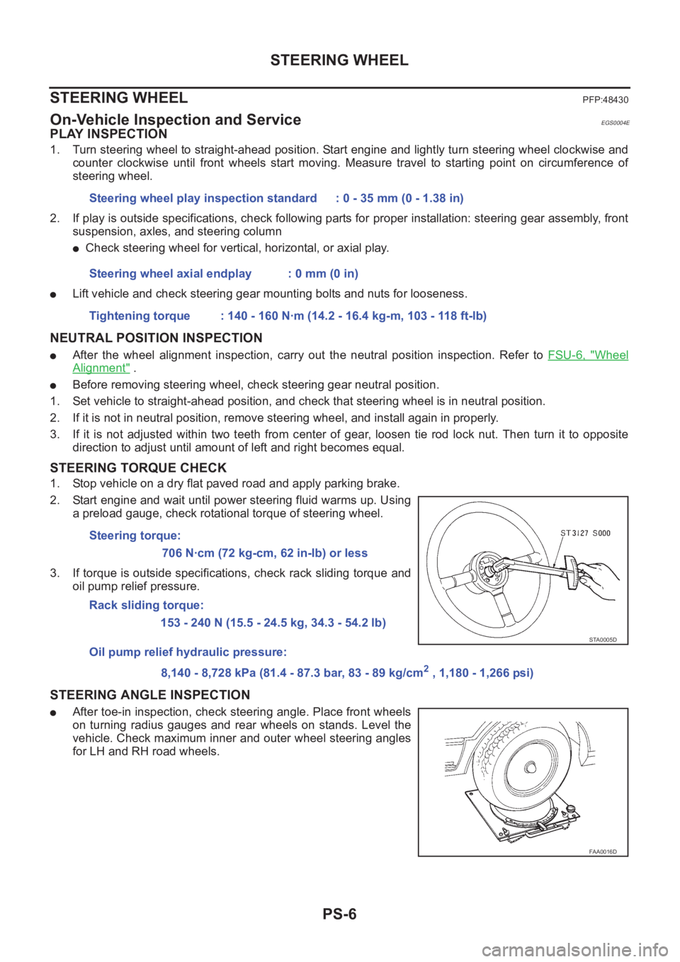
STEERING TORQUE CHECK
1. Stop vehicle on a dry flat paved road and apply parking brake.
2. Start engine and wait until power steering fluid warms up. Using
a preload gauge, check rotational torque of steering wheel.
3. If torque is outside specifications, check rack sliding torque and
oil pump relief pressure.
STEERING ANGLE INSPECTION
●After toe-in inspection, check steering angle. Place front wheels
on turning radius gauges and rear wheels on stands. Level the
vehicle. Check maximum inner and outer wheel steering angles
for LH and RH road wheels.Steering wheel play inspection standard : 0 - 35 mm (0 - 1.38 in)
Steering wheel axial endplay : 0 mm (0 in)
Tightening torque : 140 - 160 N·m (14.2 - 16.4 kg-m, 103 - 118 ft-lb)
Steering torque:
706 N·cm (72 kg-cm, 62 in-lb) or less
Rack sliding torque:
153 - 240 N (15.5 - 24.5 kg, 34.3 - 54.2 lb)
Oil pump relief hydraulic pressure:
8,140 - 8,728 kPa (81.4 - 87.3 bar, 83 - 89 kg/cm
2 , 1,180 - 1,266 psi)
STA0005D
FAA0016D