2001 NISSAN X-TRAIL oil pressure
[x] Cancel search: oil pressurePage 2934 of 3833
PS-24
POWER STEERING OIL PUMP
POWER STEERING OIL PUMP
PFP:49110
On-Vehicle Inspection and ServiceEGS000AF
OIL PUMP PULLEY HYDRAULIC PRESSURE INSPECTION
Before starting following procedure, check tension of belt.
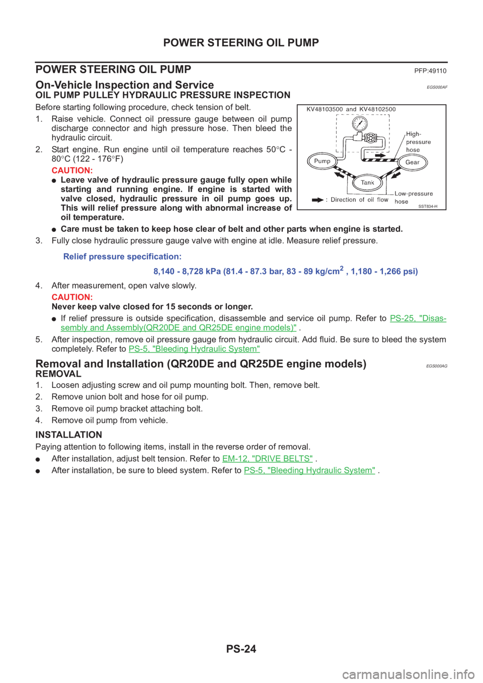
1. Raise vehicle. Connect oil pressure gauge between oil pump
discharge connector and high pressure hose. Then bleed the
hydraulic circuit.
2. Start engine. Run engine until oil temperature reaches 50°C -
80°C (122 - 176°F)
CAUTION:
●Leave valve of hydraulic pressure gauge fully open while
starting and running engine. If engine is started with
valve closed, hydraulic pressure in oil pump goes up.
This will relief pressure along with abnormal increase of
oil temperature.
●Care must be taken to keep hose clear of belt and other parts when engine is started.
3. Fully close hydraulic pressure gauge valve with engine at idle. Measure relief pressure.
4. After measurement, open valve slowly.
CAUTION:
Never keep valve closed for 15 seconds or longer.
●If relief pressure is outside specification, disassemble and service oil pump. Refer to PS-25, "Disas-
sembly and Assembly(QR20DE and QR25DE engine models)" .
5. After inspection, remove oil pressure gauge from hydraulic circuit. Add fluid. Be sure to bleed the system
completely. Refer to PS-5, "
Bleeding Hydraulic System"
Removal and Installation (QR20DE and QR25DE engine models)EGS000AG
REMOVAL
1. Loosen adjusting screw and oil pump mounting bolt. Then, remove belt.
2. Remove union bolt and hose for oil pump.
3. Remove oil pump bracket attaching bolt.
4. Remove oil pump from vehicle.
INSTALLATION
Paying attention to following items, install in the reverse order of removal.
●After installation, adjust belt tension. Refer to EM-12, "DRIVE BELTS" .
●After installation, be sure to bleed system. Refer to PS-5, "Bleeding Hydraulic System" . Relief pressure specification:
8,140 - 8,728 kPa (81.4 - 87.3 bar, 83 - 89 kg/cm
2 , 1,180 - 1,266 psi)
SST834-H
Page 2947 of 3833
SERVICE DATA AND SPECIFICATIONS (SDS)
PS-37
C
D
E
F
H
I
J
K
L
MA
B
PS
Steering GearEGS0004T
Oil PumpEGS0004U
Steering FluidEGS0004V
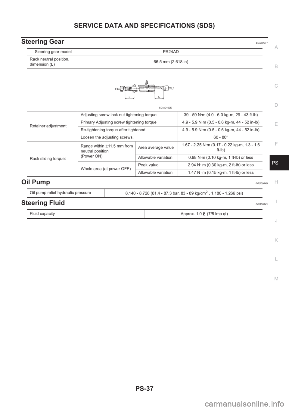
Steering gear model PR24AD
Rack neutral position,
dimension (L)66.5 mm (2.618 in)
Retainer adjustmentAdjusting screw lock nut tightening torque 39 - 59 N·m (4.0 - 6.0 kg-m, 29 - 43 ft-lb)
Primary Adjusting screw tightening torque 4.9 - 5.9 N·m (0.5 - 0.6 kg-m, 44 - 52 in-lb)
Re-tightening torque after tightened 4.9 - 5.9 N·m (0.5 - 0.6 kg-m, 44 - 52 in-lb)
Loosen the adjusting screws. 60 - 80°
Rack sliding torque:Range within ±11.5 mm from
neutral position
(Power ON)Area average value1.67 - 2.25 N·m (0.17 - 0.22 kg-m, 1.3 - 1.6
ft-lb)
Allowable variation 0.98 N·m (0.10 kg-m, 1 ft-lb) or less
Whole area (at power OFF)Peak value 2.94 N· m (0.30 kg-m, 2 ft-lb) or less
Allowable variation 1.47 N ·m (0.15 kg-m, 1 ft-lb) or less
SGIA0463E
Oil pump relief hydraulic pressure
8,140 - 8,728 (81.4 - 87.3 bar, 83 - 89 kg/cm2 , 1,180 - 1,266 psi)
Fluid capacity
Approx. 1.0 (7/8 lmp qt)
Page 3281 of 3833
PRECAUTIONS
ATC-5
C
D
E
F
G
H
I
K
L
MA
B
AT C
General Refrigerant PrecautionsEJS000T2
WARNING:
●Do not release refrigerant into the air. Use approved recovery/recycling equipment to capture the
refrigerant every time an air conditioning system is discharged.
●Always wear eye and hand protection (goggles and gloves) when working with any refrigerant or
air conditioning system.
●Do not store or heat refrigerant containers above 52°C (125°F).
●Do not heat a refrigerant container with an open flame; if container warming is required, place the
bottom of the container in a warm pail of water.
●Do not intentionally drop, puncture, or incinerate refrigerant containers.
●Keep refrigerant away from open flames: poisonous gas will be produced if refrigerant burns.
●Refrigerant will displace oxygen, therefore be certain to work in well ventilated areas to prevent
suffocation.
●Do not pressure test or leak test HFC-134a (R-134a) service equipment and/or vehicle air condi-
tioning systems with compressed air during repair. Some mixtures of air and HFC-134a (R-134a)
have been shown to be combustible at elevated pressures. These mixtures, if ignited, may cause
injury or property damage. Additional health and safety information may be obtained from refriger-
ant manufacturers.
Lubricant PrecautionsEJS0027Y
●Use only specified lubricant for the HFC-134a (R-134a) A/C system and HFC-134a (R-134a) components.
If lubricant other than that specified is used, compressor malfunction is likely to occur.
●The specified HFC-134a (R-134a) lubricant rapidly absorbs moisture from the atmosphere. The following
handling precautions must be observed:
●When removing refrigerant components from a vehicle, immediately cap (seal) the component to minimize
the entry of moisture from the atmosphere.
●When installing refrigerant components to a vehicle, do not remove the caps (unseal) until just before con-
necting the components. Connect all refrigerant loop components as quickly as possible to minimize the
entry of moisture into system.
●Only use the specified lubricant from a sealed container. Immediately reseal containers of lubricant. With-
out proper sealing, lubricant will become moisture saturated and should not be used.
●Avoid breathing A/C refrigerant and lubricant vapor or mist. Exposure may irritate eyes, nose and throat.
Remove HFC-134a (R-134a) from the A/C system, using certified service equipment meeting require-
ments of SAE J2210 HFC-134a (R-134a) recycling equipment, or J2209 HFC-134a (R-134a) recovery
equipment. If accidental system discharge occurs, ventilate work area before resuming service. Additional
health and safety information may be obtained from refrigerant and lubricant manufacturers.
●Do not allow lubricant (Nissan A/C System Oil Type S or R) to come in contact with styrofoam parts. Dam-
age may result.
Precautions for Refrigerant ConnectionEJS000T4
A new type refrigerant connection has been introduced to all refrigerant lines except the following location.
●Expansion valve to cooling unit
●Refrigerant pressure sensor to liquid tank
Page 3285 of 3833
PRECAUTIONS
ATC-9
C
D
E
F
G
H
I
K
L
MA
B
AT C
CAUTION:
When replacing or cleaning refrigerant cycle components, observe the following.
●When the compressor is removed, store it in the same position as it is when mounted on the car.
Malfunction to do so will cause lubricant to enter the low pressure chamber.
●When connecting tubes, always use a torque wrench and a back-up wrench.
●After disconnecting tubes, immediately plug all openings to prevent entry of dirt and moisture.
●When installing an air conditioner in the vehicle, connect the pipes as the final stage of the opera-
tion. Do not remove the seal caps of pipes and other components until just before required for
connection.
●Allow components stored in cool areas to warm to working area temperature before removing seal
caps. This prevents condensation from forming inside A/C components.
●Thoroughly remove moisture from the refrigeration system before charging the refrigerant.
●Always replace used O-rings.
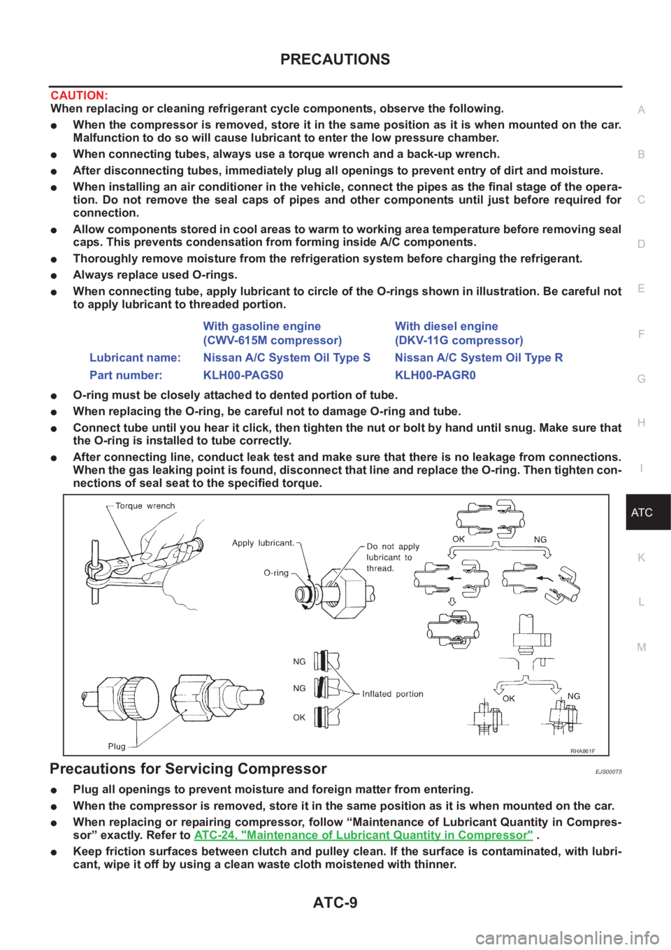
●When connecting tube, apply lubricant to circle of the O-rings shown in illustration. Be careful not
to apply lubricant to threaded portion.
●O-ring must be closely attached to dented portion of tube.
●When replacing the O-ring, be careful not to damage O-ring and tube.
●Connect tube until you hear it click, then tighten the nut or bolt by hand until snug. Make sure that
the O-ring is installed to tube correctly.
●After connecting line, conduct leak test and make sure that there is no leakage from connections.
When the gas leaking point is found, disconnect that line and replace the O-ring. Then tighten con-
nections of seal seat to the specified torque.
Precautions for Servicing CompressorEJS000T5
●Plug all openings to prevent moisture and foreign matter from entering.
●When the compressor is removed, store it in the same position as it is when mounted on the car.
●When replacing or repairing compressor, follow “Maintenance of Lubricant Quantity in Compres-
sor” exactly. Refer to ATC-24, "
Maintenance of Lubricant Quantity in Compressor" .
●Keep friction surfaces between clutch and pulley clean. If the surface is contaminated, with lubri-
cant, wipe it off by using a clean waste cloth moistened with thinner. With gasoline engine
(CWV-615M compressor)With diesel engine
(DKV-11G compressor)
Lubricant name: Nissan A/C System Oil Type S Nissan A/C System Oil Type R
Part number: KLH00-PAGS0 KLH00-PAGR0
RHA861F
Page 3294 of 3833
ATC-18
REFRIGERATION SYSTEM
REFRIGERATION SYSTEM
PFP:KA990
Refrigerant CycleEJS000TD
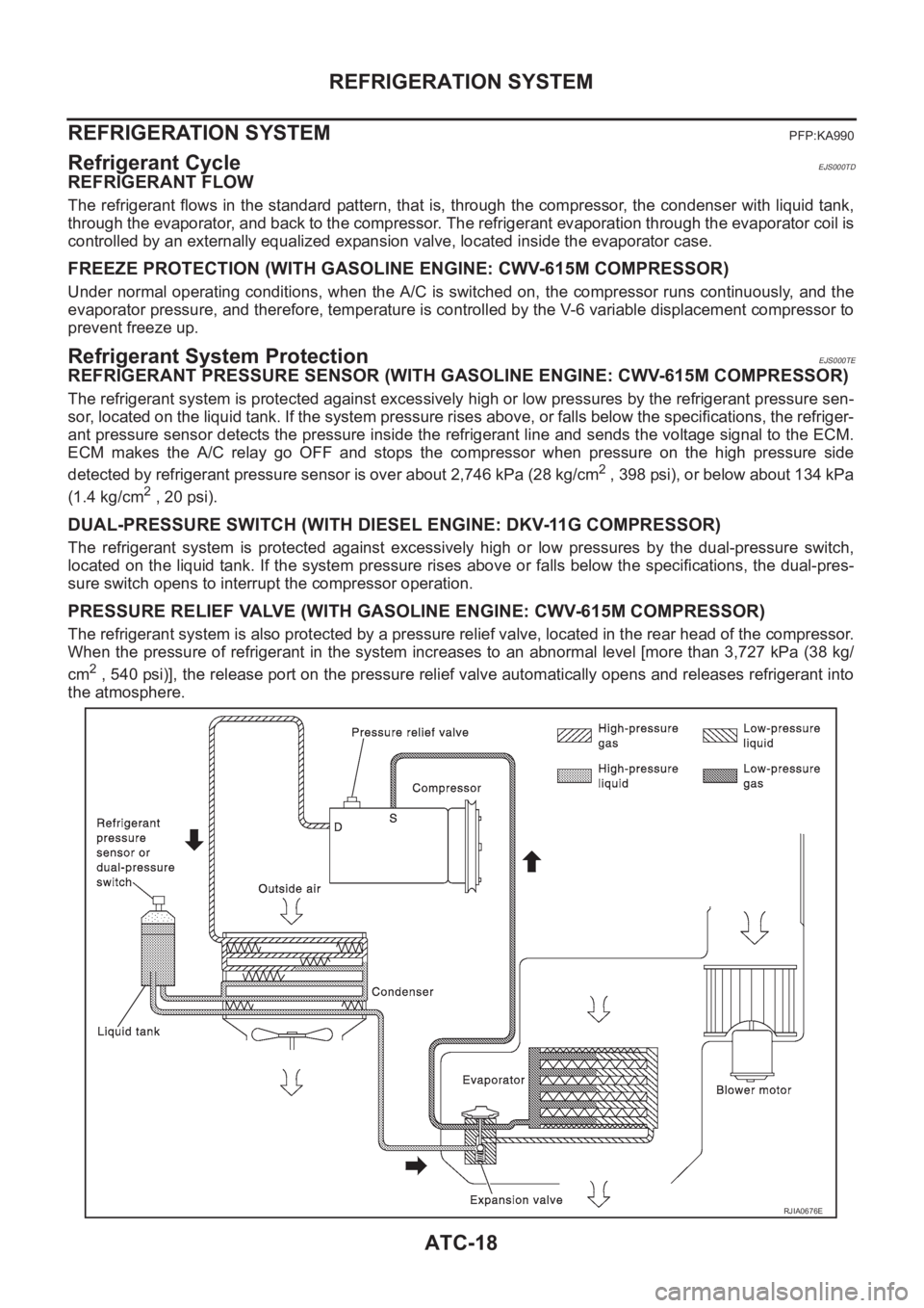
REFRIGERANT FLOW
The refrigerant flows in the standard pattern, that is, through the compressor, the condenser with liquid tank,
through the evaporator, and back to the compressor. The refrigerant evaporation through the evaporator coil is
controlled by an externally equalized expansion valve, located inside the evaporator case.
FREEZE PROTECTION (WITH GASOLINE ENGINE: CWV-615M COMPRESSOR)
Under normal operating conditions, when the A/C is switched on, the compressor runs continuously, and the
evaporator pressure, and therefore, temperature is controlled by the V-6 variable displacement compressor to
prevent freeze up.
Refrigerant System ProtectionEJS000TE
REFRIGERANT PRESSURE SENSOR (WITH GASOLINE ENGINE: CWV-615M COMPRESSOR)
The refrigerant system is protected against excessively high or low pressures by the refrigerant pressure sen-
sor, located on the liquid tank. If the system pressure rises above, or falls below the specifications, the refriger-
ant pressure sensor detects the pressure inside the refrigerant line and sends the voltage signal to the ECM.
ECM makes the A/C relay go OFF and stops the compressor when pressure on the high pressure side
detected by refrigerant pressure sensor is over about 2,746 kPa (28 kg/cm
2 , 398 psi), or below about 134 kPa
(1.4 kg/cm
2 , 20 psi).
DUAL-PRESSURE SWITCH (WITH DIESEL ENGINE: DKV-11G COMPRESSOR)
The refrigerant system is protected against excessively high or low pressures by the dual-pressure switch,
located on the liquid tank. If the system pressure rises above or falls below the specifications, the dual-pres-
sure switch opens to interrupt the compressor operation.
PRESSURE RELIEF VALVE (WITH GASOLINE ENGINE: CWV-615M COMPRESSOR)
The refrigerant system is also protected by a pressure relief valve, located in the rear head of the compressor.
When the pressure of refrigerant in the system increases to an abnormal level [more than 3,727 kPa (38 kg/
cm
2 , 540 psi)], the release port on the pressure relief valve automatically opens and releases refrigerant into
the atmosphere.
RJIA0676E
Page 3357 of 3833
TROUBLE DIAGNOSIS
ATC-81
C
D
E
F
G
H
I
K
L
MA
B
AT C
4.CHECK A/C RELAY AFTER DISCONNECTING IT
Refer to ATC-84, "
A/C Relay" .
OK or NG
OK >> Reconnect A/C relay. And GO TO 5.
NG >> 1. replace A/C relay.
2. Go to self-diagnosis AT C - 4 7 , "
PROCEDURE" and perform self-diagnosis STEP-4.Confirm that
magnet clutch operation is normal.
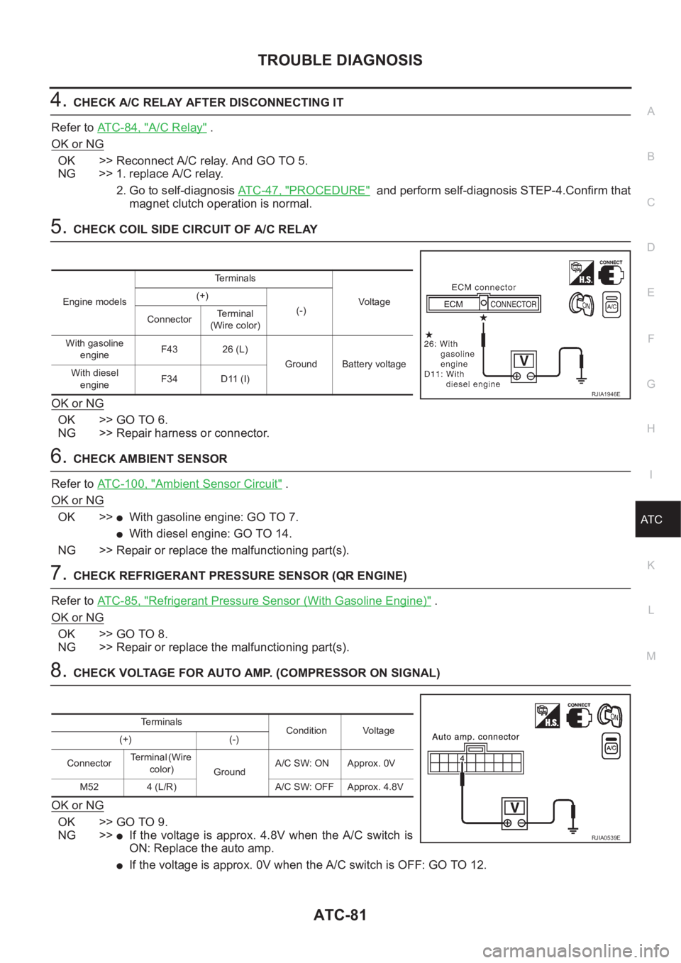
5.CHECK COIL SIDE CIRCUIT OF A/C RELAY
OK or NG
OK >> GO TO 6.
NG >> Repair harness or connector.
6.CHECK AMBIENT SENSOR
Refer to ATC-100, "
Ambient Sensor Circuit" .
OK or NG
OK >>●With gasoline engine: GO TO 7.
●With diesel engine: GO TO 14.
NG >> Repair or replace the malfunctioning part(s).
7.CHECK REFRIGERANT PRESSURE SENSOR (QR ENGINE)
Refer to ATC-85, "
Refrigerant Pressure Sensor (With Gasoline Engine)" .
OK or NG
OK >> GO TO 8.
NG >> Repair or replace the malfunctioning part(s).
8.CHECK VOLTAGE FOR AUTO AMP. (COMPRESSOR ON SIGNAL)
OK or NG
OK >> GO TO 9.
NG >>
●If the voltage is approx. 4.8V when the A/C switch is
ON: Replace the auto amp.
●If the voltage is approx. 0V when the A/C switch is OFF: GO TO 12.
Engine modelsTerminals
Voltag e (+)
(-)
ConnectorTerminal
(Wire color)
With gasoline
engineF43 26 (L)
Ground Battery voltage
With diesel
engineF34 D11 (I)
RJIA1946E
Terminals
Condition Voltage
(+) (-)
ConnectorTe r m i n a l ( W i r e
color)
GroundA/C SW: ON Approx. 0V
M52 4 (L/R) A/C SW: OFF Approx. 4.8V
RJIA0539E
Page 3361 of 3833
TROUBLE DIAGNOSIS
ATC-85
C
D
E
F
G
H
I
K
L
MA
B
AT C
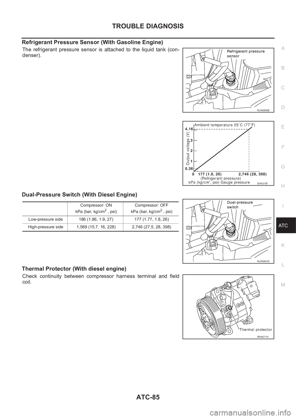
Refrigerant Pressure Sensor (With Gasoline Engine)
The refrigerant pressure sensor is attached to the liquid tank (con-
denser).
Dual-Pressure Switch (With Diesel Engine)
Thermal Protector (With diesel engine)
Check continuity between compressor harness terminal and field
coil.
RJIA0690E
SHA315F
Compressor: ON
kPa (bar, kg/cm2 , psi)Compressor: OFF
kPa (bar, kg/cm2 , psi)
Low-pressure side 186 (1.86, 1.9, 27) 177 (1.77, 1.8, 26)
High-pressure side 1,569 (15.7, 16, 228) 2,746 (27.5, 28, 398)
RJIA0691E
RHA671H
Page 3410 of 3833
ATC-134
REFRIGERANT LINES
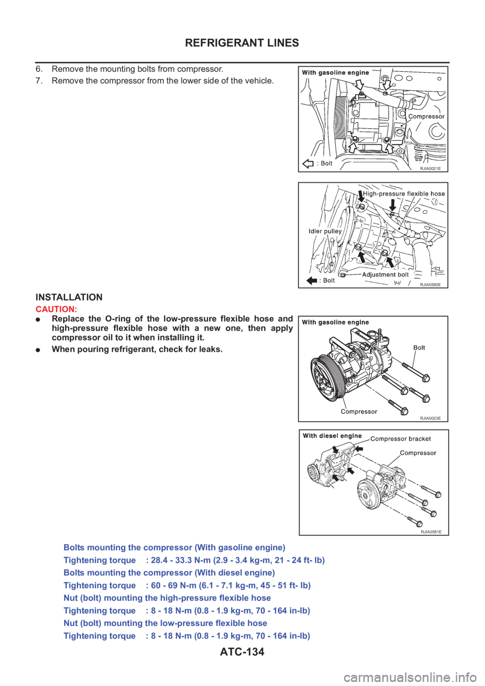
6. Remove the mounting bolts from compressor.
7. Remove the compressor from the lower side of the vehicle.
INSTALLATION
CAUTION:
●Replace the O-ring of the low-pressure flexible hose and
high-pressure flexible hose with a new one, then apply
compressor oil to it when installing it.
●When pouring refrigerant, check for leaks.
RJIA0021E
RJIA0580E
RJIA0023E
RJIA0581E
Bolts mounting the compressor (With gasoline engine)
Tightening torque : 28.4 - 33.3 N-m (2.9 - 3.4 kg-m, 21 - 24 ft- lb)
Bolts mounting the compressor (With diesel engine)
Tightening torque : 60 - 69 N-m (6.1 - 7.1 kg-m, 45 - 51 ft- lb)
Nut (bolt) mounting the high-pressure flexible hose
Tightening torque : 8 - 18 N-m (0.8 - 1.9 kg-m, 70 - 164 in-lb)
Nut (bolt) mounting the low-pressure flexible hose
Tightening torque : 8 - 18 N-m (0.8 - 1.9 kg-m, 70 - 164 in-lb)