2001 NISSAN X-TRAIL ignition
[x] Cancel search: ignitionPage 2665 of 3833
TROUBLE DIAGNOSIS
TF-55
C
E
F
G
H
I
J
K
L
MA
B
TF
Trouble Diagnoses for SymptomsEDS000IS
4WD INDICATOR LAMP DOSE NOT COME ON FOR APPROXIMATELY 1 SECOND WHEN THE
IGNITION SWITCH IS TURNED TO ON
Inspection Procedure
1.CHECK BLOWN FUSES BETWEEN IGN AND COMBINATION METER
Check that there are no blown fuses between IGN and combination meter.
OK or NG
OK >> GO TO 2.
NG >> Replace fuse and check again.
2.CHECK CONTINUITY BETWEEN COMBINATION METER AND 4WD CONTROL UNIT
1. Disconnect combination meter connector and 4WD control unit connector.
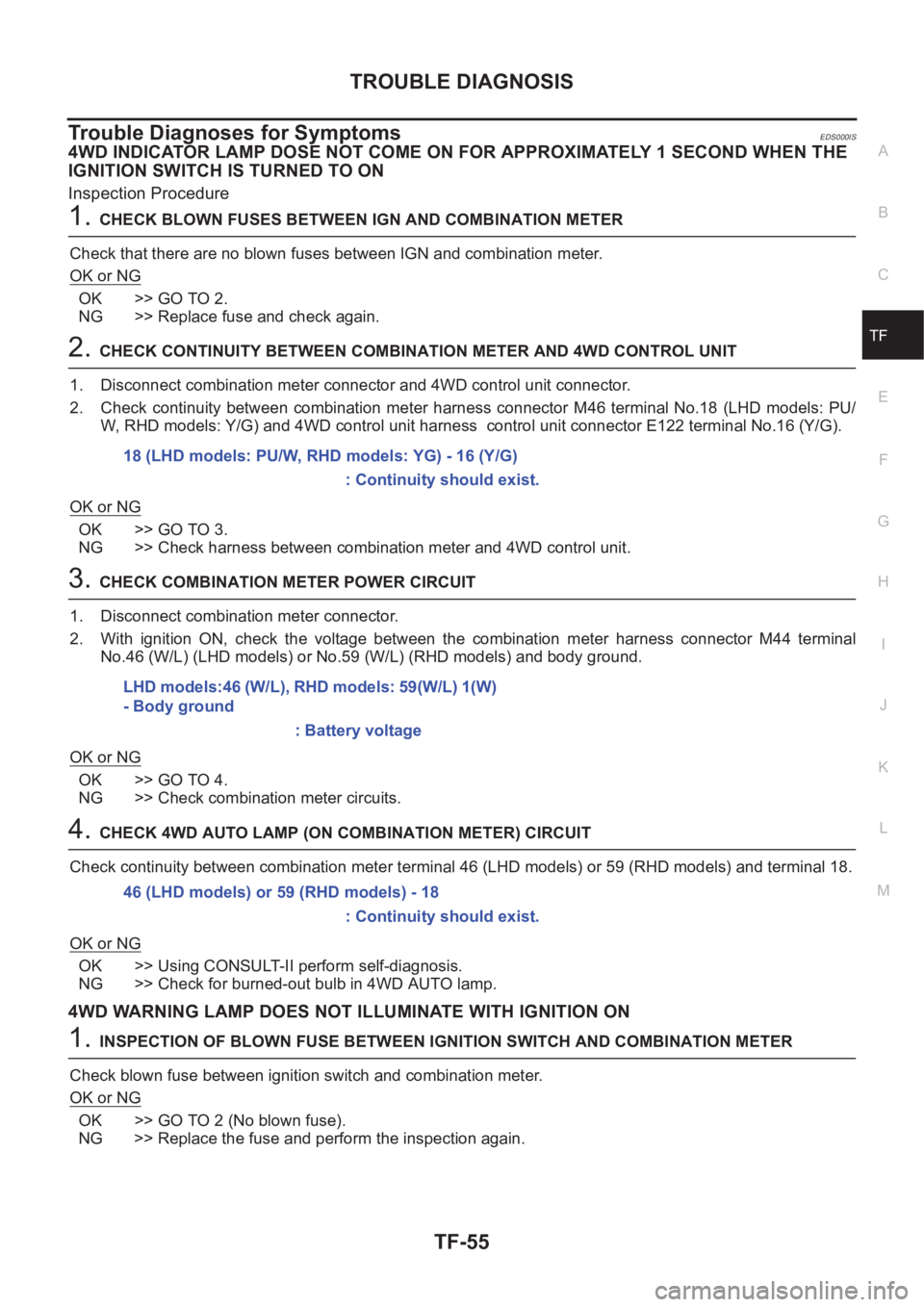
2. Check continuity between combination meter harness connector M46 terminal No.18 (LHD models: PU/
W, RHD models: Y/G) and 4WD control unit harness control unit connector E122 terminal No.16 (Y/G).
OK or NG
OK >> GO TO 3.
NG >> Check harness between combination meter and 4WD control unit.
3.CHECK COMBINATION METER POWER CIRCUIT
1. Disconnect combination meter connector.
2. With ignition ON, check the voltage between the combination meter harness connector M44 terminal
No.46 (W/L) (LHD models) or No.59 (W/L) (RHD models) and body ground.
OK or NG
OK >> GO TO 4.
NG >> Check combination meter circuits.
4.CHECK 4WD AUTO LAMP (ON COMBINATION METER) CIRCUIT
Check continuity between combination meter terminal 46 (LHD models) or 59 (RHD models) and terminal 18.
OK or NG
OK >> Using CONSULT-II perform self-diagnosis.
NG >> Check for burned-out bulb in 4WD AUTO lamp.
4WD WARNING LAMP DOES NOT ILLUMINATE WITH IGNITION ON
1.INSPECTION OF BLOWN FUSE BETWEEN IGNITION SWITCH AND COMBINATION METER
Check blown fuse between ignition switch and combination meter.
OK or NG
OK >> GO TO 2 (No blown fuse).
NG >> Replace the fuse and perform the inspection again.18 (LHD models: PU/W, RHD models: YG) - 16 (Y/G)
: Continuity should exist.
LHD models:46 (W/L), RHD models: 59(W/L) 1(W)
- Body ground
: Battery voltage
46 (LHD models) or 59 (RHD models) - 18
: Continuity should exist.
Page 2743 of 3833
PRECAUTIONS
BR-3
C
D
E
G
H
I
J
K
L
MA
B
BR
PRECAUTIONSPFP:00001
Precautions for Supplemental Restraint System (SRS) “AIR BAG” and “SEAT
BELT PRE-TENSIONER”
EFS002F9
The Supplemental Restraint System such as “AIR BAG” and “SEAT BELT PRE-TENSIONER”, used along
with a front seat belt, helps to reduce the risk or severity of injury to the driver and front passenger for certain
types of collision. Information necessary to service the system safely is included in the SRS and SB section of
this Service Manual.
WARNING:
●To avoid rendering the SRS inoperative, which could increase the risk of personal injury or death
in the event of a collision which would result in air bag inflation, all maintenance must be per-
formed by an authorized NISSAN/INFINITI dealer.
●Improper maintenance, including incorrect removal and installation of the SRS, can lead to per-
sonal injury caused by unintentional activation of the system. For removal of Spiral Cable and Air
Bag Module, see the SRS section.
●Do not use electrical test equipment on any circuit related to the SRS unless instructed to in this
Service Manual. SRS wiring harnesses can be identified by yellow and/or orange harness connec-
tors.
Precautions for Brake SystemEFS000BZ
●Clean dust on brake pads, shoes, drums, and back plates with a vacuum dust collector. Do not blow with
compressed air.
●Recommended fluid is brake fluid “DOT 3” or “DOT 4”.
●Never reuse drained brake fluid.
●Be careful not to splash brake fluid on painted areas such as the body. If brake fluid is splashed or spilled
on paint, wipe it off and flush the area with water immediately.
●Use only clean brake fluid when cleaning master cylinder and disc brake components.
●Never use mineral oils such as gasoline or kerosene to clean. They will ruin the rubber parts and cause
improper operation.
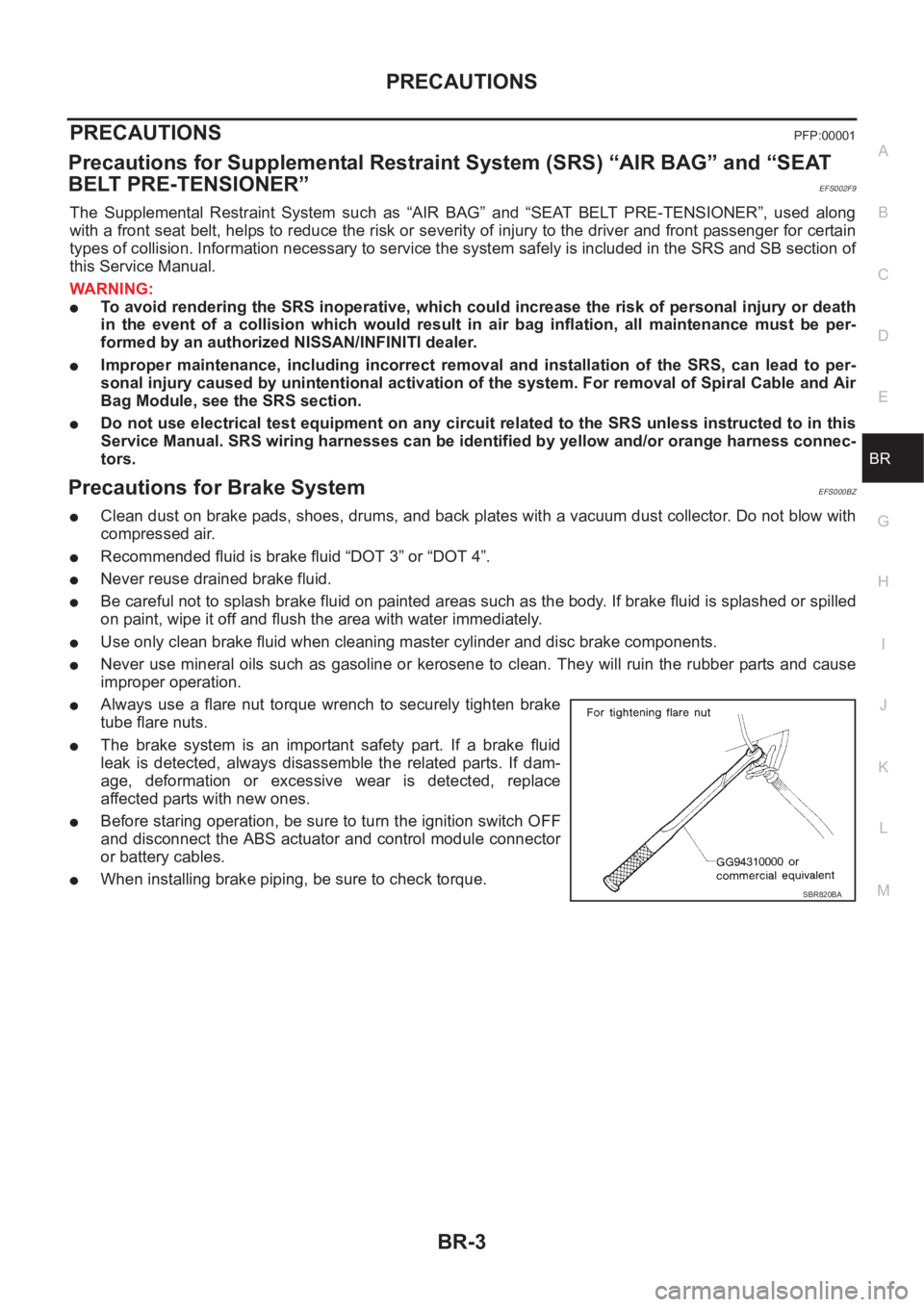
●Always use a flare nut torque wrench to securely tighten brake
tube flare nuts.
●The brake system is an important safety part. If a brake fluid
leak is detected, always disassemble the related parts. If dam-
age, deformation or excessive wear is detected, replace
affected parts with new ones.
●Before staring operation, be sure to turn the ignition switch OFF
and disconnect the ABS actuator and control module connector
or battery cables.
●When installing brake piping, be sure to check torque.SBR820BA
Page 2749 of 3833
BRAKE FLUID
BR-9
C
D
E
G
H
I
J
K
L
MA
B
BR
BRAKE FLUIDPFP:KN100
Checking Brake Fluid Level EFS000C5
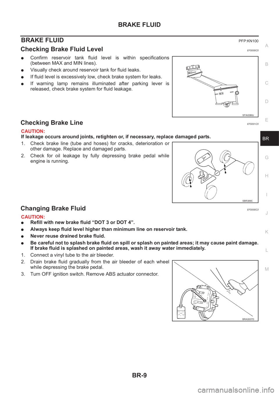
●Confirm reservoir tank fluid level is within specifications
(between MAX and MIN lines).
●Visually check around reservoir tank for fluid leaks.
●If fluid level is excessively low, check brake system for leaks.
●If warning lamp remains illuminated after parking lever is
released, check brake system for fluid leakage.
Checking Brake LineEFS001C5
CAUTION:
If leakage occurs around joints, retighten or, if necessary, replace damaged parts.
1. Check brake line (tube and hoses) for cracks, deterioration or
other damage. Replace and damaged parts.
2. Check for oil leakage by fully depressing brake pedal while
engine is running.
Changing Brake FluidEFS000C3
CAUTION:
●Refill with new brake fluid “DOT 3 or DOT 4”.
●Always keep fluid level higher than minimum line on reservoir tank.
●Never reuse drained brake fluid.
●Be careful not to splash brake fluid on spill or splash on painted areas; it may cause paint damage.
If brake fluid is splashed on painted areas, wash it away water immediately.
1. Connect a vinyl tube to the air bleeder.
2. Drain brake fluid gradually from the air bleeder of each wheel
while depressing the brake pedal.
3. Turn OFF ignition switch. Remove ABS actuator connector.
SFIA0066J
SBR389C
BRA0007D
Page 2750 of 3833
BR-10
BRAKE FLUID
4. Be sure there is no foreign material in reservoir tank. Refill with
new brake fluid.
5. Connect a vinyl tube to the air bleeder.
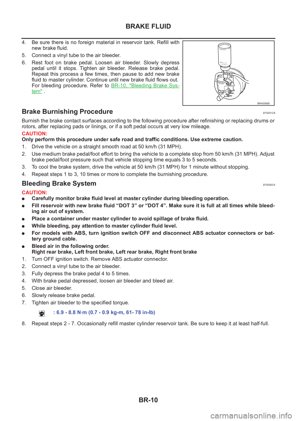
6. Rest foot on brake pedal. Loosen air bleeder. Slowly depress
pedal until it stops. Tighten air bleeder. Release brake pedal.
Repeat this process a few times, then pause to add new brake
fluid to master cylinder. Continue until new brake fluid flows out.
For bleeding procedure. Refer to BR-10, "
Bleeding Brake Sys-
tem" .
Brake Burnishing ProcedureEFS001C8
Burnish the brake contact surfaces according to the following procedure after refinishing or replacing drums or
rotors, after replacing pads or linings, or if a soft pedal occurs at very low mileage.
CAUTION:
Only perform this procedure under safe road and traffic conditions. Use extreme caution.
1. Drive the vehicle on a straight smooth road at 50 km/h (31 MPH).
2. Use medium brake pedal/foot effort to bring the vehicle to a complete stop from 50 km/h (31 MPH). Adjust
brake pedal/foot pressure such that vehicle stopping time equals 3 to 5 seconds.
3. To cool the brake system, drive the vehicle at 50 km/h (31 MPH) for 1 minute without stopping.
4. Repeat steps 1 to 3, 10 times or more to complete the burnishing procedure.
Bleeding Brake SystemEFS000C4
CAUTION:
●Carefully monitor brake fluid level at master cylinder during bleeding operation.
●Fill reservoir with new brake fluid “DOT 3” or “DOT 4”. Make sure it is full at all times while bleed-
ing air out of system.
●Place a container under master cylinder to avoid spillage of brake fluid.
●While bleeding, pay attention to master cylinder fluid level.
●For models with ABS, turn ignition switch OFF and disconnect ABS actuator connectors or bat-
tery ground cable.
●Bleed air in the following order.
Right rear brake, Left front brake, Left rear brake, Right front brake
1. Turn OFF ignition switch. Remove ABS actuator connector.
2. Connect a vinyl tube to the air bleeder.
3. Fully depress the brake pedal 4 to 5 times.
4. With brake pedal depressed, loosen air bleeder and bleed air.
5. Close air bleeder.
6. Slowly release brake pedal.
7. Tighten air bleeder to the specified torque.
8. Repeat steps 2 - 7. Occasionally refill master cylinder reservoir tank. Be sure to keep it at least half-full.
BRA0006D
: 6.9 - 8.8 N·m (0.7 - 0.9 kg-m, 61- 78 in-lb)
Page 2785 of 3833
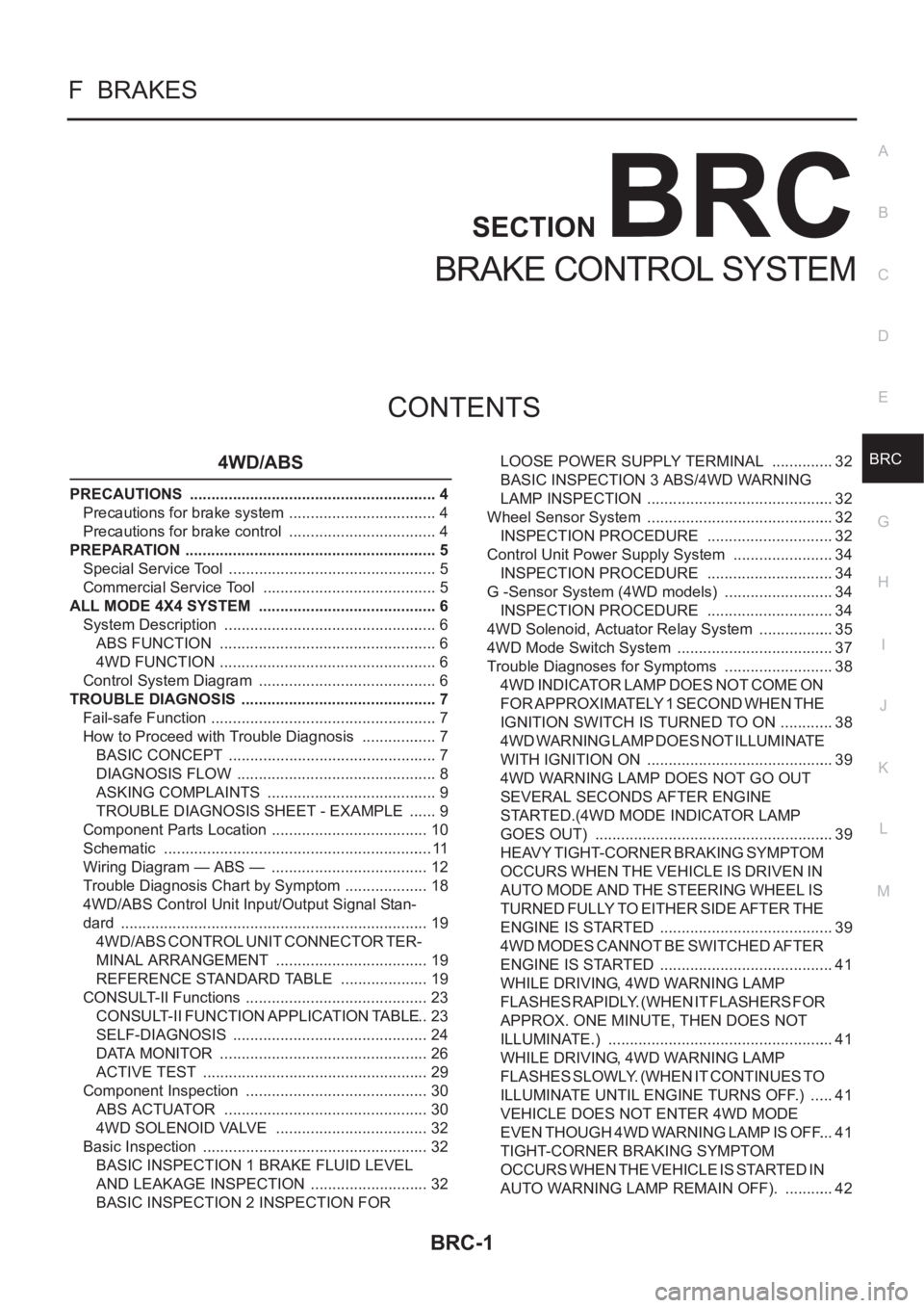
BRC-1
BRAKE CONTROL SYSTEM
F BRAKES
CONTENTS
C
D
E
G
H
I
J
K
L
M
SECTION
A
B
BRC
BRAKE CONTROL SYSTEM
4WD/ABS
PRECAUTIONS .......................................................... 4
Precautions for brake system ................................... 4
Precautions for brake control ................................... 4
PREPARATION ........................................................... 5
Special Service Tool ................................................. 5
Commercial Service Tool ......................................... 5
ALL MODE 4X4 SYSTEM .......................................... 6
System Description .................................................. 6
ABS FUNCTION ................................................... 6
4WD FUNCTION ................................................... 6
Control System Diagram .......................................... 6
TROUBLE DIAGNOSIS .............................................. 7
Fail-safe Function ..................................................... 7
How to Proceed with Trouble Diagnosis .................. 7
BASIC CONCEPT ................................................. 7
DIAGNOSIS FLOW ............................................... 8
ASKING COMPLAINTS ........................................ 9
TROUBLE DIAGNOSIS SHEET - EXAMPLE ....... 9
Component Parts Location ..................................... 10
Schematic ............................................................... 11
Wiring Diagram — ABS — ..................................... 12
Trouble Diagnosis Chart by Symptom .................... 18
4WD/ABS Control Unit Input/Output Signal Stan-
dard ........................................................................ 19
4WD/ABS CONTROL UNIT CONNECTOR TER-
MINAL ARRANGEMENT .................................... 19
REFERENCE STANDARD TABLE ..................... 19
CONSULT-II Functions ........................................... 23
CONSULT-II FUNCTION APPLICATION TABLE ... 23
SELF-DIAGNOSIS .............................................. 24
DATA MONITOR ................................................. 26
ACTIVE TEST ..................................................... 29
Component Inspection ........................................... 30
ABS ACTUATOR ................................................ 30
4WD SOLENOID VALVE .................................... 32
Basic Inspection ..................................................... 32
BASIC INSPECTION 1 BRAKE FLUID LEVEL
AND LEAKAGE INSPECTION ............................ 32
BASIC INSPECTION 2 INSPECTION FOR LOOSE POWER SUPPLY TERMINAL ............... 32
BASIC INSPECTION 3 ABS/4WD WARNING
LAMP INSPECTION ............................................ 32
Wheel Sensor System ............................................ 32
INSPECTION PROCEDURE .............................. 32
Control Unit Power Supply System ........................ 34
INSPECTION PROCEDURE .............................. 34
G -Sensor System (4WD models) .......................... 34
INSPECTION PROCEDURE .............................. 34
4WD Solenoid, Actuator Relay System .................. 35
4WD Mode Switch System ..................................... 37
Trouble Diagnoses for Symptoms .......................
... 38
4WD INDICATOR LAMP DOES NOT COME ON
FOR APPROXIMATELY 1 SECOND WHEN THE
IGNITION SWITCH IS TURNED TO ON ............. 38
4WD WARNING LAMP DOES NOT ILLUMINATE
WITH IGNITION ON ............................................ 39
4WD WARNING LAMP DOES NOT GO OUT
SEVERAL SECONDS AFTER ENGINE
STARTED.(4WD MODE INDICATOR LAMP
GOES OUT) ........................................................ 39
HEAVY TIGHT-CORNER BRAKING SYMPTOM
OCCURS WHEN THE VEHICLE IS DRIVEN IN
AUTO MODE AND THE STEERING WHEEL IS
TURNED FULLY TO EITHER SIDE AFTER THE
ENGINE IS STARTED ......................................... 39
4WD MODES CANNOT BE SWITCHED AFTER
ENGINE IS STARTED ......................................... 41
WHILE DRIVING, 4WD WARNING LAMP
FLASHES RAPIDLY. (WHEN IT FLASHERS FOR
APPROX. ONE MINUTE, THEN DOES NOT
ILLUMINATE.) ..................................................... 41
WHILE DRIVING, 4WD WARNING LAMP
FLASHES SLOWLY. (WHEN IT CONTINUES TO
ILLUMINATE UNTIL ENGINE TURNS OFF.) ...... 41
VEHICLE DOES NOT ENTER 4WD MODE
EVEN THOUGH 4WD WARNING LAMP IS OFF. ... 41
TIGHT-CORNER BRAKING SYMPTOM
OCCURS WHEN THE VEHICLE IS STARTED IN
AUTO WARNING LAMP REMAIN OFF). ............ 42
Page 2786 of 3833
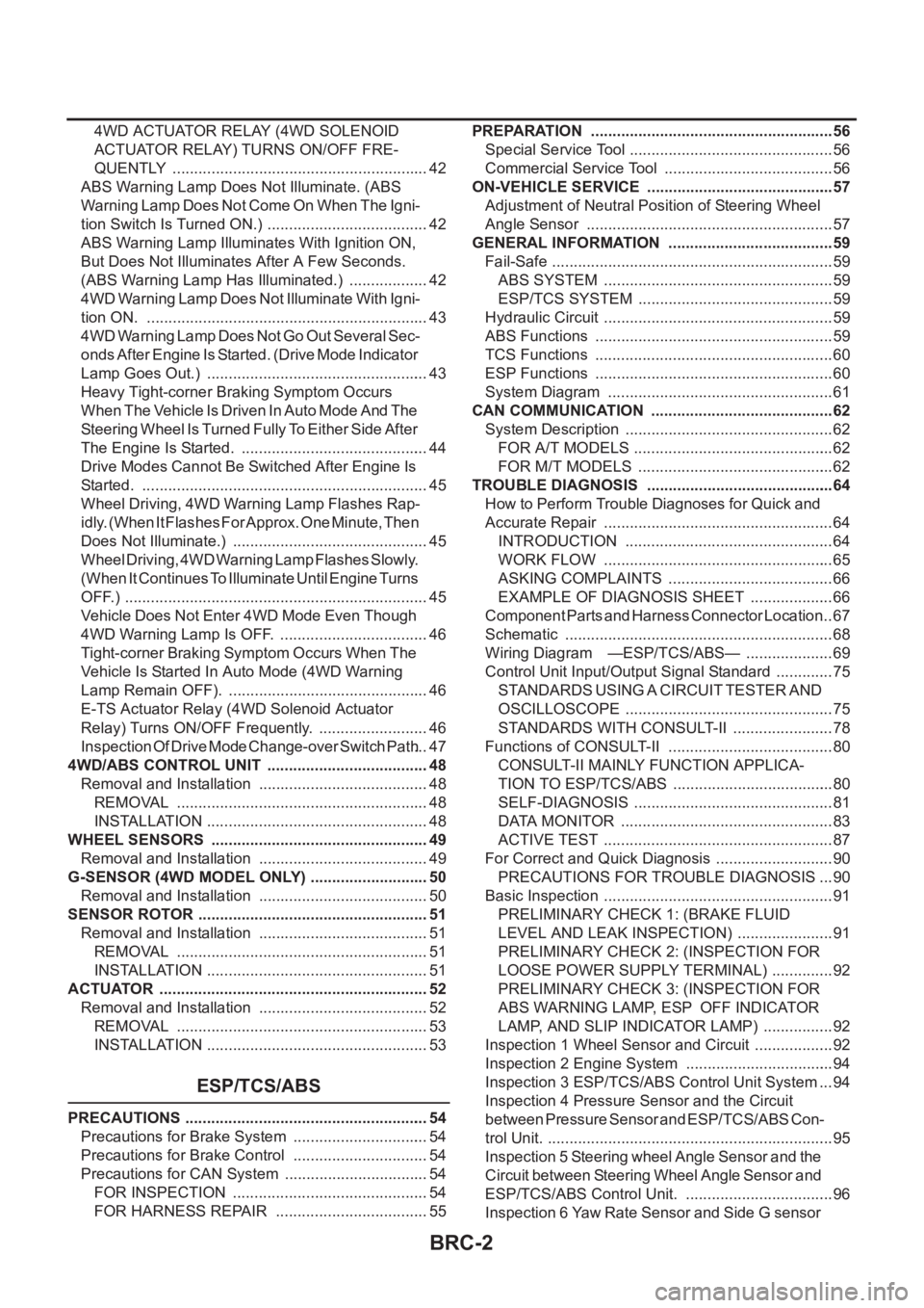
BRC-2
4WD ACTUATOR RELAY (4WD SOLENOID
A C T U AT O R R E L AY ) T U R N S O N / O F F F R E -
QUENTLY ............................................................ 42
ABS Warning Lamp Does Not Illuminate. (ABS
Warning Lamp Does Not Come On When The Igni-
tion Switch Is Turned ON.) ...................................... 42
ABS Warning Lamp Illuminates With Ignition ON,
But Does Not Illuminates After A Few Seconds.
(ABS Warning Lamp Has Illuminated.) ................... 42
4WD Warning Lamp Does Not Illuminate With Igni-
tion ON. .................................................................. 43
4WD Warning Lamp Does Not Go Out Several Sec-
onds After Engine Is Started. (Drive Mode Indicator
Lamp Goes Out.) .................................................... 43
Heavy Tight-corner Braking Symptom Occurs
When The Vehicle Is Driven In Auto Mode And The
Steering Wheel Is Turned Fully To Either Side After
The Engine Is Started. ............................................ 44
Drive Modes Cannot Be Switched After Engine Is
Started. ................................................................... 45
Wheel Driving, 4WD Warning Lamp Flashes Rap-
idly. (When It Flashes For Approx. One Minute, Then
Does Not Illuminate.) .............................................. 45
Wheel Driving, 4WD Warning Lamp Flashes Slowly.
(When It Continues To Illuminate Until Engine Turns
OFF.) ....................................................................... 45
Vehicle Does Not Enter 4WD Mode Even Though
4WD Warning Lamp Is OFF. ................................... 46
Tight-corner Braking Symptom Occurs When The
Vehicle Is Started In Auto Mode (4WD Warning
Lamp Remain OFF). ............................................... 46
E-TS Actuator Relay (4WD Solenoid Actuator
Relay) Turns ON/OFF Frequently. .......................... 46
Inspection Of Drive Mode Change-over Switch Path ... 47
4WD/ABS CONTROL UNIT ...................................... 48
Removal and Installation ........................................ 48
REMOVAL ........................................................... 48
INSTALLATION .................................................... 48
WHEEL SENSORS ................................................... 49
Removal and Installation ........................................ 49
G-SENSOR (4WD MODEL ONLY) ............................ 50
Removal and Installation ........................................ 50
SENSOR ROTOR ................................................... ... 51
Removal and Installation ........................................ 51
REMOVAL ........................................................... 51
INSTALLATION .................................................... 51
ACTUATOR ............................................................... 52
Removal and Installation ........................................ 52
REMOVAL ........................................................... 53
INSTALLATION .................................................... 53
ESP/TCS/ABS
PRECAUTIONS ......................................................... 54
Precautions for Brake System ................................ 54
Precautions for Brake Control ................................ 54
Precautions for CAN System .................................. 54
FOR INSPECTION .............................................. 54
FOR HARNESS REPAIR .................................... 55PREPARATION ......................................................... 56
Special Service Tool ................................................ 56
Commercial Service Tool ........................................ 56
ON-VEHICLE SERVICE ............................................ 57
Adjustment of Neutral Position of Steering Wheel
Angle Sensor .......................................................... 57
GENERAL INFORMATION ....................................... 59
Fail-Safe .................................................................. 59
ABS SYSTEM ...................................................... 59
ESP/TCS SYSTEM .............................................. 59
Hydraulic Circuit ...................................................... 59
ABS Functions ........................................................ 59
TCS Functions ........................................................ 60
ESP Functions ........................................................ 60
System Diagram ..................................................... 61
CAN COMMUNICATION ........................................... 62
System Description ................................................. 62
FOR A/T MODELS ............................................... 62
FOR M/T MODELS .............................................. 62
TROUBLE DIAGNOSIS ............................................ 64
How to Perform Trouble Diagnoses for Quick and
Accurate Repair ...................................................... 64
INTRODUCTION ................................................. 64
WORK FLOW ...................................................... 65
ASKING COMPLAINTS ....................................... 66
EXAMPLE OF DIAGNOSIS SHEET .................... 66
Component Parts and Harness Connector Location ... 67
Schematic ............................................................... 68
Wiring Diagram —ESP/TCS/ABS— ..................... 69
Control Unit Input/Output Signal Standard .............. 75
STANDARDS USING A CIRCUIT TESTER AND
OSCILLOSCOPE ................................................. 75
STANDARDS WITH CONSULT-II ........................ 78
Functions of CONSULT-II ....................................... 80
CONSULT-II MAINLY FUNCTION APPLICA-
TION TO ESP/TCS/ABS ...................................... 80
SELF-DIAGNOSIS ............................................... 81
DATA MONITOR .................................................. 83
ACTIVE TEST ...................................................... 87
For Correct and Quick Diagnosis ............................ 90
PRECAUTIONS FOR TROUBLE DIAGNOSIS ... 90
Basic Inspection ...................................................... 91
PRELIMINARY CHECK 1: (BRAKE FLUID
LEVEL AND LEAK INSPECTION) ....................... 91
PRELIMINARY CHECK 2: (INSPECTION FOR
LOOSE POWER SUPPLY TERMINAL) ............... 92
PRELIMINARY CHECK 3: (INSPECTION FOR
ABS WARNING LAMP, ESP OFF INDICATOR
LAMP, AND SLIP INDICATOR LAMP) ................. 92
Inspection 1 Wheel Sensor and Circuit ................... 92
Inspection 2 Engine System ................................... 94
Inspection 3 ESP/TCS/ABS Control Unit System ... 94
Inspection 4 Pressure Sensor and the Circuit
between Pressure Sensor and ESP/TCS/ABS Con-
trol Unit. ................................................................... 95
Inspection 5 Steering wheel Angle Sensor and the
Circuit between Steering Wheel Angle Sensor and
ESP/TCS/ABS Control Unit. ................................... 96
Inspection 6 Yaw Rate Sensor and Side G sensor
Page 2788 of 3833
![NISSAN X-TRAIL 2001 Service Repair Manual BRC-4
[4WD/ABS]
PRECAUTIONS
[4WD/ABS]PRECAUTIONSPFP:00001
Precautions for brake systemEFS001B6
●Recommended fluid is brake fluid “DOT 3 ”or “DOT 4”.
●Never reuse drained brake fluid.
●Be NISSAN X-TRAIL 2001 Service Repair Manual BRC-4
[4WD/ABS]
PRECAUTIONS
[4WD/ABS]PRECAUTIONSPFP:00001
Precautions for brake systemEFS001B6
●Recommended fluid is brake fluid “DOT 3 ”or “DOT 4”.
●Never reuse drained brake fluid.
●Be](/manual-img/5/57405/w960_57405-2787.png)
BRC-4
[4WD/ABS]
PRECAUTIONS
[4WD/ABS]PRECAUTIONSPFP:00001
Precautions for brake systemEFS001B6
●Recommended fluid is brake fluid “DOT 3 ”or “DOT 4”.
●Never reuse drained brake fluid.
●Be careful not to splash brake fluid on painted areas.
●To clean or wash all parts of master cylinder, disc brake caliper and wheel cylinder, use clean brake fluid.
●Never use mineral oils such as gasoline or kerosene. They will ruin rubber parts of the hydraulic system.
●Use flare nut wrench when removing and installing brake tube.
●Always torque brake lines when installing.
●Burnish the brake contact surfaces after refinishing or replacing
drums or rotors, after replacing pads or linings, or if a soft pedal
occurs at very low mileage. Refer to BR-10, "
Brake Burnishing
Procedure" .
●Before working, turn OFF ignition switch. Disconnect connectors
for ABS actuator and control module or battery terminals.
WARNING:
●Clean brake pads and shoes with a waste cloth, then wipe
with a dust collector.
Precautions for brake controlEFS001B7
●If malfunction is indicated by 4WD warning lamp and/or ABS warning lamp, collect necessary information
from customer (what symptoms are present under what conditions). Find out possible causes before start-
ing service. Besides electrical system inspection, check operation of ABS actuator.
●If malfunction is detected, proceed to trouble diagnosis after checking tire pressure and tire wear.
●Stopping distance or steering stability may be deteriorated by the following conditions. Tire size and type
are in improper combination. Brake pads are not Nissan genuine parts.
●Fitting tires of different size on vehicle can be cause of longitudinal vibration. Always use tires of the same
size and brand. Exchange front and rear tires on the following conditions: Longitudinal vibration occurs in
vehicle with tires of the same size and brand. After replacement, perform trouble diagnosis. 1580|None
●4WD/ABS function may have a failure or error under following condition: There is radio, antenna, or
antenna lead-in wire (including wiring) near control module.
●If aftermarket parts (e.g. Car stereo equipment, CD player) have been installed, check electrical har-
nesses for pinches, open, and improper wiring.
SBR820BA
Page 2802 of 3833
![NISSAN X-TRAIL 2001 Service Repair Manual BRC-18
[4WD/ABS]
TROUBLE DIAGNOSIS
Trouble Diagnosis Chart by Symptom
EFS001BF
When ABS and 4WD warning lamps illuminate, perform self-diagnosis.
Symptom Condition Check items Reference page
4wd indic NISSAN X-TRAIL 2001 Service Repair Manual BRC-18
[4WD/ABS]
TROUBLE DIAGNOSIS
Trouble Diagnosis Chart by Symptom
EFS001BF
When ABS and 4WD warning lamps illuminate, perform self-diagnosis.
Symptom Condition Check items Reference page
4wd indic](/manual-img/5/57405/w960_57405-2801.png)
BRC-18
[4WD/ABS]
TROUBLE DIAGNOSIS
Trouble Diagnosis Chart by Symptom
EFS001BF
When ABS and 4WD warning lamps illuminate, perform self-diagnosis.
Symptom Condition Check items Reference page
4wd indicator lamp does not come on
for approximately 1 second when the
ignition switch is turned on.IGN-ON
●Blown drive mode indicator lamp bulb
●Blown fuse between ignition and drive mode
indicator lamp
●Open circuit of wiring between ignition and
drive mode indicator lampBRC-42
ABS warning lamp does not illuminate
with ignition ON. (ABS warning lamp
check)IGN-ON
●Blown ABS warning lamp bulb
●Blown fuse between ignition and ABS warning
lamp.
●Open circuit of wiring between ignition and
ABS warning lamp.
●Malfunction in ABS systemBRC-42
ABS warning lamp illuminates with
ignition ON, but does not illuminates
after a few seconds. (ABS warning
lamp has not illuminated.)IGN-ON●4WD/ABS control unit connector discon-
nected
●Malfunction in ABS systemBRC-42
4WD warning lamp does not illuminate
with ignition ON.IGN-ON
●Blown 4WD warning lamp bulb
●Blown fuse between ignition and 4WD warn-
ing lamp
●Open circuit in wire between ignition and 4WD
warning lamp
●Open circuit in wire between 4WD warning
lamp and 4WD actuator relay
●Disconnected 4WD actuator relay
●Open circuit in wire between 4WD actuator
relay and body groundBRC-43
4WD warning lamp does not go out
several seconds after engine is started.
(Drive mode indicator lamp goes out.)Engine running●4WD/ABS control unit connector discon-
nected
●Malfunction present in 4WD systemBRC-43
Heavy tight-corner braking symptom
occurs when vehicle is driven in the fol-
lowing conditions: AUTO mode and
steering wheel is turned fully to either
sides after engine is started (Note 1,
Note 2).●Engine run-
ning
●AUTO mode
●Steering
wheel fully
turned
●Operation is not in AUTO mode (in 2WD or
LOCK mode).
●Throttle position signal error
●Mechanical malfunction of electronically con-
trolled coupling
●Malfunction present in 4WD systemBRC-44
Drive modes cannot be switched after
engine is started.Engine running
●Drive mode change-over switch is discon-
nected.
●Open circuit between drive mode change-over
switch and 4WD /ABS control unit
●Open circuit between drive mode change-over
switch and body groundBRC-45
Vehicle running, 4WD warning lamp
flashes rapidly. (When it flashes for
Approx. One minute, then does not illu-
minate.) Rapid flashing: Two times
flashing per 1 secondEngine running
(to other than
2WD mode)Protection function was activated due to heavy
load to electronically controlled coupling. (4WD
system is not malfunctioning.)BRC-45