2001 NISSAN PICK-UP sensor
[x] Cancel search: sensorPage 305 of 1306
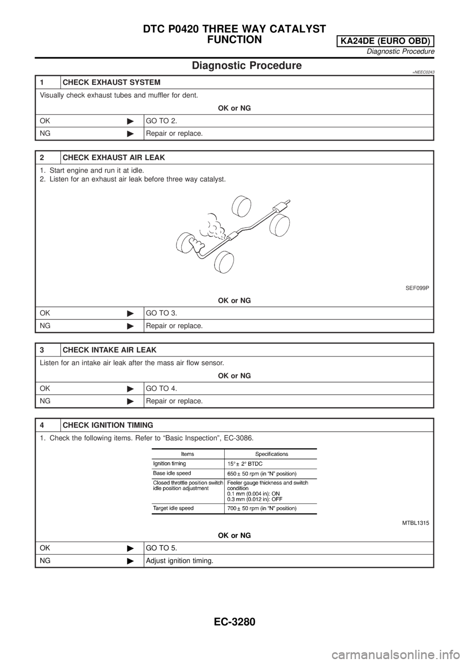
Diagnostic Procedure=NEEC0243
1 CHECK EXHAUST SYSTEM
Visually check exhaust tubes and muffler for dent.
OK or NG
OK©GO TO 2.
NG©Repair or replace.
2 CHECK EXHAUST AIR LEAK
1. Start engine and run it at idle.
2. Listen for an exhaust air leak before three way catalyst.
SEF099P
OK or NG
OK©GO TO 3.
NG©Repair or replace.
3 CHECK INTAKE AIR LEAK
Listen for an intake air leak after the mass air flow sensor.
OK or NG
OK©GO TO 4.
NG©Repair or replace.
4 CHECK IGNITION TIMING
1. Check the following items. Refer to ªBasic Inspectionº, EC-3086.
MTBL1315
OK or NG
OK©GO TO 5.
NG©Adjust ignition timing.
DTC P0420 THREE WAY CATALYST
FUNCTION
KA24DE (EURO OBD)
Diagnostic Procedure
EC-3280
Page 307 of 1306
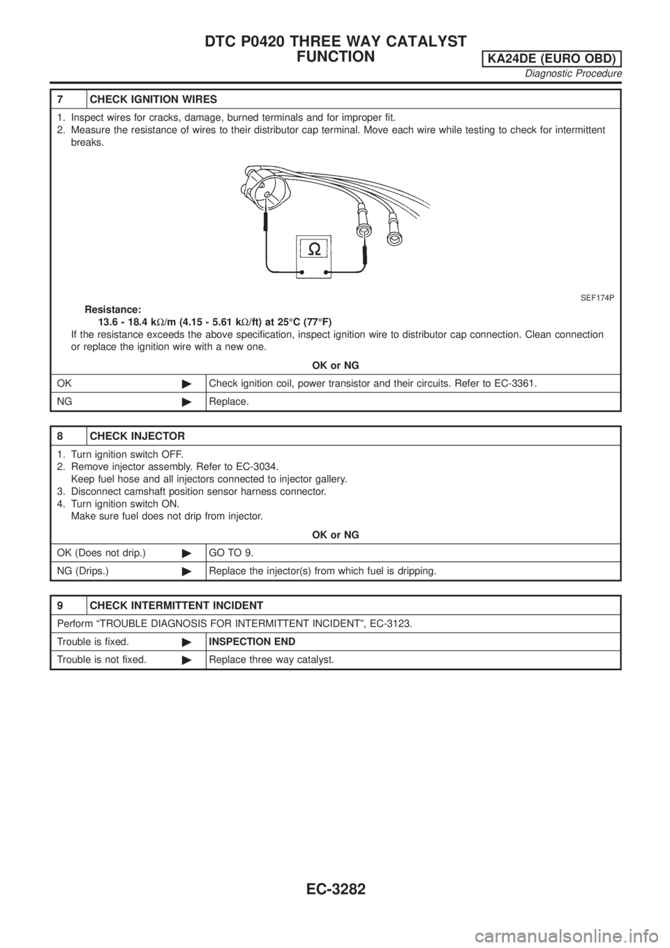
7 CHECK IGNITION WIRES
1. Inspect wires for cracks, damage, burned terminals and for improper fit.
2. Measure the resistance of wires to their distributor cap terminal. Move each wire while testing to check for intermittent
breaks.
SEF174P
Resistance:
13.6 - 18.4 kW/m (4.15 - 5.61 kW/ft) at 25ÉC (77ÉF)
If the resistance exceeds the above specification, inspect ignition wire to distributor cap connection. Clean connection
or replace the ignition wire with a new one.
OK or NG
OK©Check ignition coil, power transistor and their circuits. Refer to EC-3361.
NG©Replace.
8 CHECK INJECTOR
1. Turn ignition switch OFF.
2. Remove injector assembly. Refer to EC-3034.
Keep fuel hose and all injectors connected to injector gallery.
3. Disconnect camshaft position sensor harness connector.
4. Turn ignition switch ON.
Make sure fuel does not drip from injector.
OK or NG
OK (Does not drip.)©GO TO 9.
NG (Drips.)©Replace the injector(s) from which fuel is dripping.
9 CHECK INTERMITTENT INCIDENT
Perform ªTROUBLE DIAGNOSIS FOR INTERMITTENT INCIDENTº, EC-3123.
Trouble is fixed.©INSPECTION END
Trouble is not fixed.©Replace three way catalyst.
DTC P0420 THREE WAY CATALYST
FUNCTION
KA24DE (EURO OBD)
Diagnostic Procedure
EC-3282
Page 308 of 1306
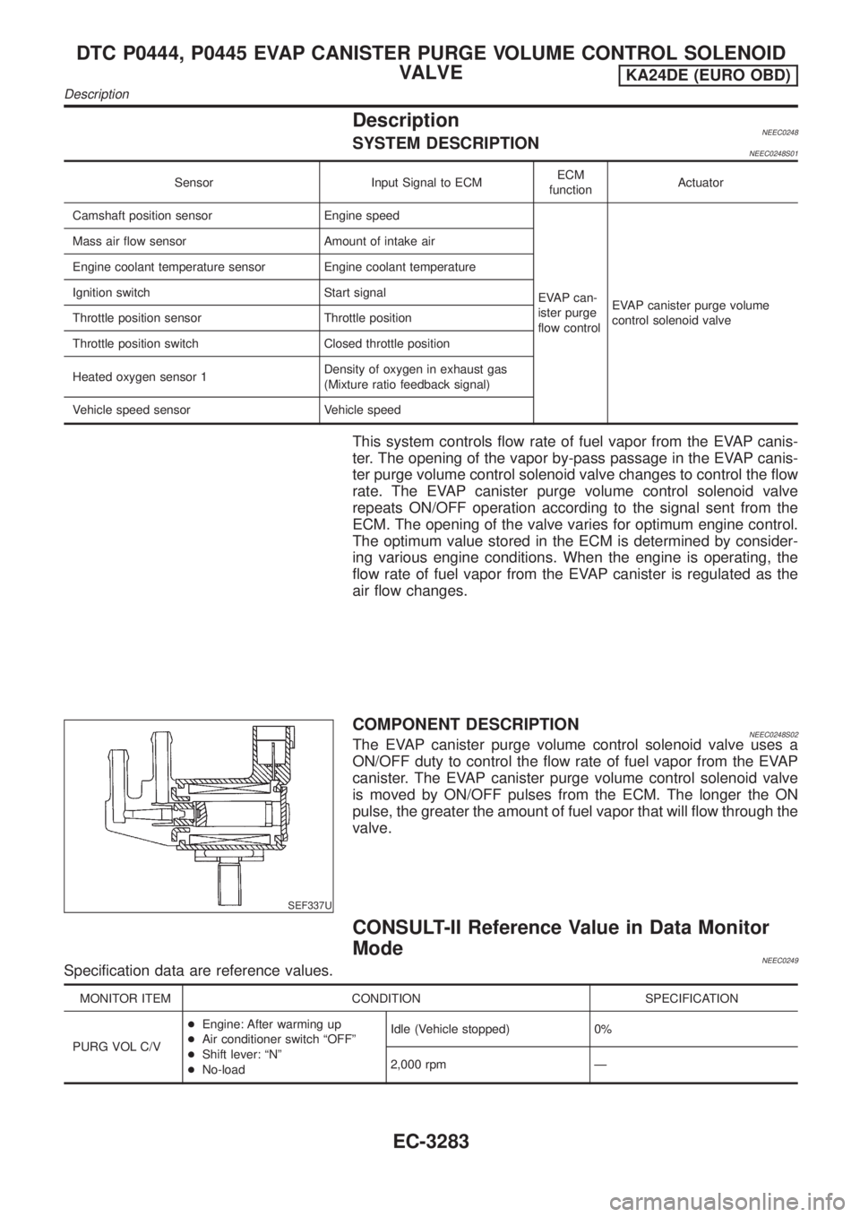
DescriptionNEEC0248SYSTEM DESCRIPTIONNEEC0248S01
Sensor Input Signal to ECMECM
functionActuator
Camshaft position sensor Engine speed
EVAP can-
ister purge
flow controlEVAP canister purge volume
control solenoid valve Mass air flow sensor Amount of intake air
Engine coolant temperature sensor Engine coolant temperature
Ignition switch Start signal
Throttle position sensor Throttle position
Throttle position switch Closed throttle position
Heated oxygen sensor 1Density of oxygen in exhaust gas
(Mixture ratio feedback signal)
Vehicle speed sensor Vehicle speed
This system controls flow rate of fuel vapor from the EVAP canis-
ter. The opening of the vapor by-pass passage in the EVAP canis-
ter purge volume control solenoid valve changes to control the flow
rate. The EVAP canister purge volume control solenoid valve
repeats ON/OFF operation according to the signal sent from the
ECM. The opening of the valve varies for optimum engine control.
The optimum value stored in the ECM is determined by consider-
ing various engine conditions. When the engine is operating, the
flow rate of fuel vapor from the EVAP canister is regulated as the
air flow changes.
SEF337U
COMPONENT DESCRIPTIONNEEC0248S02The EVAP canister purge volume control solenoid valve uses a
ON/OFF duty to control the flow rate of fuel vapor from the EVAP
canister. The EVAP canister purge volume control solenoid valve
is moved by ON/OFF pulses from the ECM. The longer the ON
pulse, the greater the amount of fuel vapor that will flow through the
valve.
CONSULT-II Reference Value in Data Monitor
Mode
NEEC0249Specification data are reference values.
MONITOR ITEM CONDITION SPECIFICATION
PURG VOL C/V+Engine: After warming up
+Air conditioner switch ªOFFº
+Shift lever: ªNº
+No-loadIdle (Vehicle stopped) 0%
2,000 rpm Ð
DTC P0444, P0445 EVAP CANISTER PURGE VOLUME CONTROL SOLENOID
VALVE
KA24DE (EURO OBD)
Description
EC-3283
Page 309 of 1306
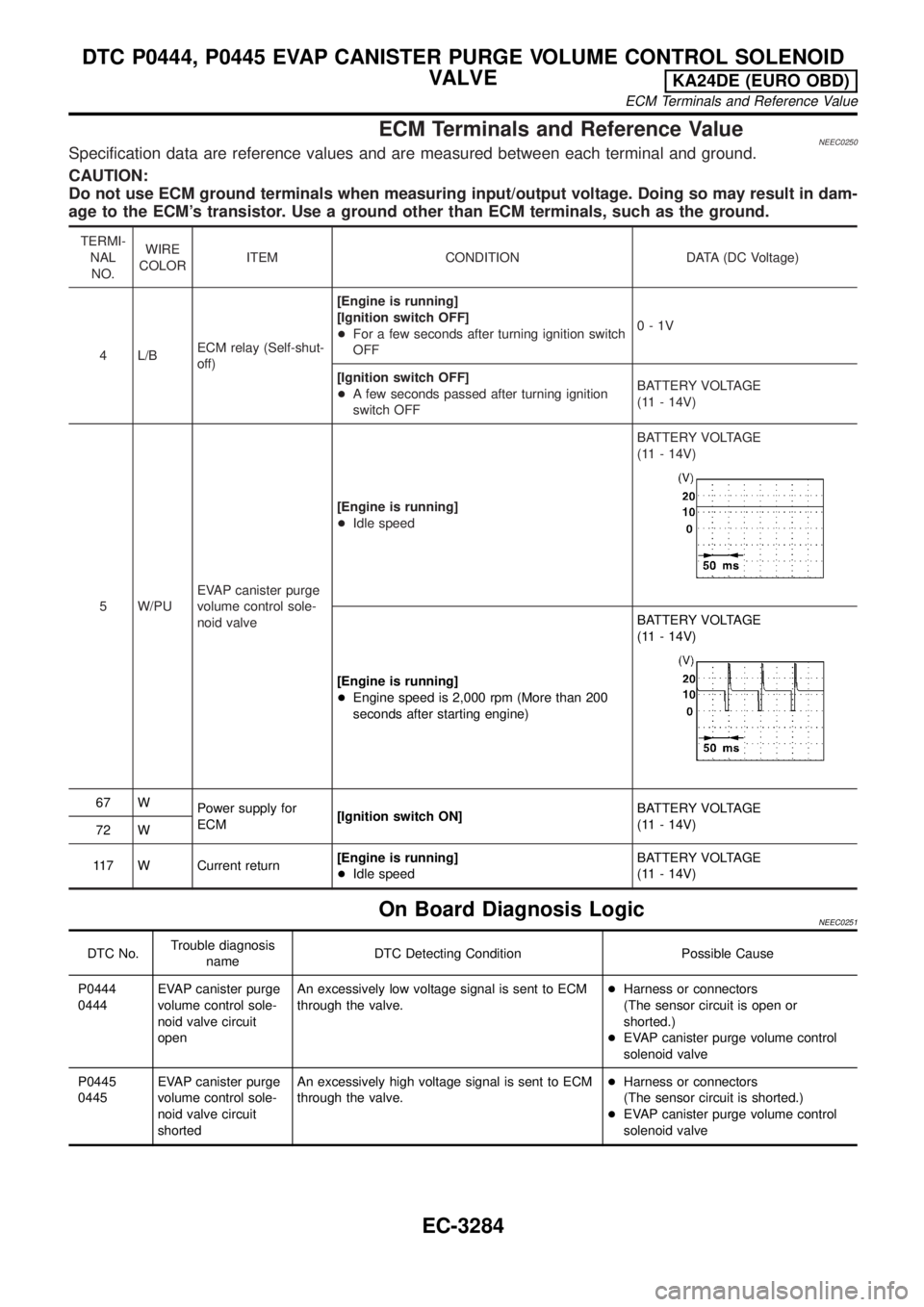
ECM Terminals and Reference ValueNEEC0250Specification data are reference values and are measured between each terminal and ground.
CAUTION:
Do not use ECM ground terminals when measuring input/output voltage. Doing so may result in dam-
age to the ECM's transistor. Use a ground other than ECM terminals, such as the ground.
TERMI-
NAL
NO.WIRE
COLORITEM CONDITION DATA (DC Voltage)
4 L/BECM relay (Self-shut-
off)[Engine is running]
[Ignition switch OFF]
+For a few seconds after turning ignition switch
OFF0-1V
[Ignition switch OFF]
+A few seconds passed after turning ignition
switch OFFBATTERY VOLTAGE
(11 - 14V)
5 W/PUEVAP canister purge
volume control sole-
noid valve[Engine is running]
+Idle speedBATTERY VOLTAGE
(11 - 14V)
[Engine is running]
+Engine speed is 2,000 rpm (More than 200
seconds after starting engine)BATTERY VOLTAGE
(11 - 14V)
67 W
Power supply for
ECM[Ignition switch ON]BATTERY VOLTAGE
(11 - 14V)
72 W
117 W Current return[Engine is running]
+Idle speedBATTERY VOLTAGE
(11 - 14V)
On Board Diagnosis LogicNEEC0251
DTC No.Trouble diagnosis
nameDTC Detecting Condition Possible Cause
P0444
0444EVAP canister purge
volume control sole-
noid valve circuit
openAn excessively low voltage signal is sent to ECM
through the valve.+Harness or connectors
(The sensor circuit is open or
shorted.)
+EVAP canister purge volume control
solenoid valve
P0445
0445EVAP canister purge
volume control sole-
noid valve circuit
shortedAn excessively high voltage signal is sent to ECM
through the valve.+Harness or connectors
(The sensor circuit is shorted.)
+EVAP canister purge volume control
solenoid valve
DTC P0444, P0445 EVAP CANISTER PURGE VOLUME CONTROL SOLENOID
VALVE
KA24DE (EURO OBD)
ECM Terminals and Reference Value
EC-3284
Page 315 of 1306
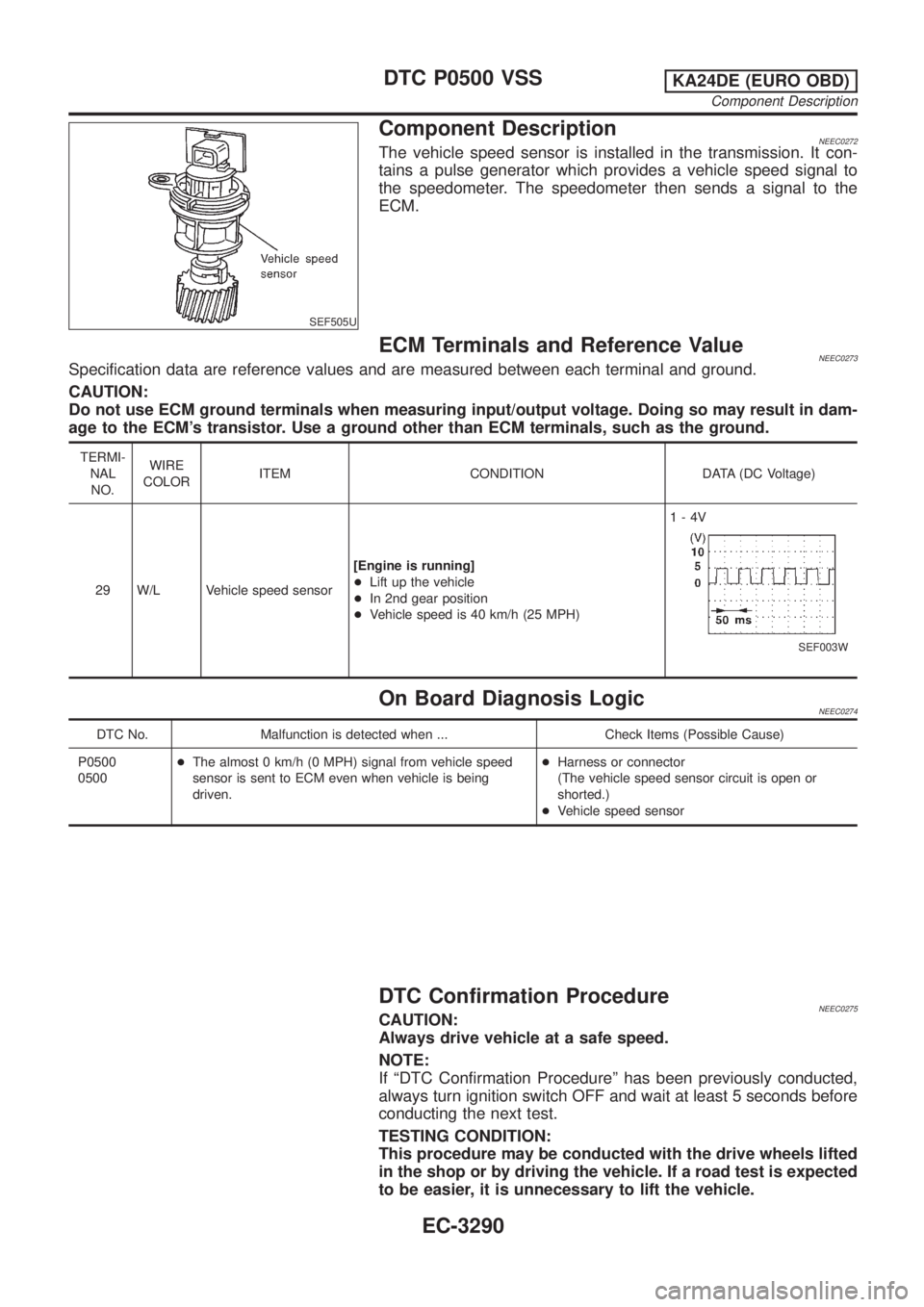
SEF505U
Component DescriptionNEEC0272The vehicle speed sensor is installed in the transmission. It con-
tains a pulse generator which provides a vehicle speed signal to
the speedometer. The speedometer then sends a signal to the
ECM.
ECM Terminals and Reference ValueNEEC0273Specification data are reference values and are measured between each terminal and ground.
CAUTION:
Do not use ECM ground terminals when measuring input/output voltage. Doing so may result in dam-
age to the ECM's transistor. Use a ground other than ECM terminals, such as the ground.
TERMI-
NAL
NO.WIRE
COLORITEM CONDITION DATA (DC Voltage)
29 W/L Vehicle speed sensor[Engine is running]
+Lift up the vehicle
+In 2nd gear position
+Vehicle speed is 40 km/h (25 MPH)1-4V
SEF003W
On Board Diagnosis LogicNEEC0274
DTC No. Malfunction is detected when ... Check Items (Possible Cause)
P0500
0500+The almost 0 km/h (0 MPH) signal from vehicle speed
sensor is sent to ECM even when vehicle is being
driven.+Harness or connector
(The vehicle speed sensor circuit is open or
shorted.)
+Vehicle speed sensor
DTC Confirmation ProcedureNEEC0275CAUTION:
Always drive vehicle at a safe speed.
NOTE:
If ªDTC Confirmation Procedureº has been previously conducted,
always turn ignition switch OFF and wait at least 5 seconds before
conducting the next test.
TESTING CONDITION:
This procedure may be conducted with the drive wheels lifted
in the shop or by driving the vehicle. If a road test is expected
to be easier, it is unnecessary to lift the vehicle.
DTC P0500 VSSKA24DE (EURO OBD)
Component Description
EC-3290
Page 316 of 1306

SEF196Y
With CONSULT-II
1) Start engine
2) Read vehicle speed sensor signal in ªDATA MONITORº mode
with CONSULT-II. The vehicle speed on CONSULT-II should
exceed 10 km/h (6 MPH) when rotating wheels with suitable
gear position.
3) If NG, go to ªDiagnostic Procedureº, EC-3294.
If OK, go to following step.
4) Select ªDATA MONITORº mode with CONSULT-II.
5) Warm engine up to normal operating temperature.
6) Maintain the following conditions for at least 1 minute.
ENG SPEED 1,800 - 6,000 rpm
COOLAN TEMP/S More than 70ÉC (158ÉF)
B/FUEL SCHDL 7 - 15 msec
Selector lever Suitable position
PW/ST SIGNAL OFF
7) If 1st trip DTC is detected, go to ªDiagnostic Procedureº,
EC-3294.
SEF568P
Overall Function CheckNEEC0276Use this procedure to check the overall function of the EVAP can-
ister vent control valve circuit. During this check, a 1st trip DTC
might not be confirmed.
With GST
1) Lift up drive wheels.
2) Start engine.
3) Read vehicle speed sensor signal in ªMODE 1º with GST.
The vehicle speed sensor on GST should be able to exceed
10 km/h (6 MPH) when rotating wheels with suitable gear posi-
tion.
4) If NG, go to ªDiagnostic Procedureº, EC-3294.
DTC P0500 VSSKA24DE (EURO OBD)
DTC Confirmation Procedure
EC-3291
Page 319 of 1306

Diagnostic ProcedureNEEC1054WITH TACHOMETERNEEC1054S01
1 CHECK INPUT SIGNAL CIRCUIT
1. Turn ignition switch OFF.
2. Disconnect ECM harness connector and combination meter harness connector.
MTBL1308
3. Check harness continuity between ECM terminal 29 and meter terminal 57 (With tachometer), 28 (Without tachometer).
Refer to Wiring Diagram.
Continuity should exist.
4. Also check harness for short to ground and short to power.
OK or NG
OK©GO TO 3.
NG©GO TO 2.
2 DETECT MALFUNCTIONING PART
Check the following.
+Harness connectors N2, M7
+Harness for open or short between ECM and combination meter
©Repair open circuit or short to ground or short to power in harness or connectors.
3 CHECK SPEEDOMETER FUNCTION
Make sure that speedometer functions properly.
OK or NG
OK©GO TO 5.
NG©GO TO 4.
4 DETECT MALFUNCTIONING PART
Check the following.
+Harness connectors N2, M7
+Harness connectors M5, E101
+Harness connectors E30, E203
+Harness for open or short between combination meter and vehicle speed sensor
©Repair harness or connectors. Check vehicle speed sensor and its circuit. Refer to EL
section.
5 CHECK INTERMITTENT INCIDENT
Perform ªTROUBLE DIAGNOSIS FOR INTERMITTENT INCIDENTº, EC-3123.
©INSPECTION END
DTC P0500 VSSKA24DE (EURO OBD)
Diagnostic Procedure
EC-3294
Page 320 of 1306
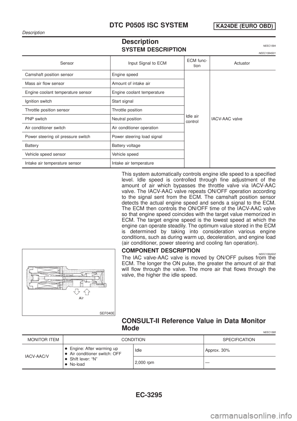
DescriptionNEEC1594SYSTEM DESCRIPTIONNEEC1594S01
Sensor Input Signal to ECMECM func-
tionActuator
Camshaft position sensor Engine speed
Idle air
controlIACV-AAC valve Mass air flow sensor Amount of intake air
Engine coolant temperature sensor Engine coolant temperature
Ignition switch Start signal
Throttle position sensor Throttle position
PNP switch Neutral position
Air conditioner switch Air conditioner operation
Power steering oil pressure switch Power steering load signal
Battery Battery voltage
Vehicle speed sensor Vehicle speed
Intake air temperature sensor Intake air temperature
This system automatically controls engine idle speed to a specified
level. Idle speed is controlled through fine adjustment of the
amount of air which bypasses the throttle valve via IACV-AAC
valve. The IACV-AAC valve repeats ON/OFF operation according
to the signal sent from the ECM. The camshaft position sensor
detects the actual engine speed and sends a signal to the ECM.
The ECM then controls the ON/OFF time of the IACV-AAC valve
so that engine speed coincides with the target value memorized in
ECM. The target engine speed is the lowest speed at which the
engine can operate steadily. The optimum value stored in the ECM
is determined by taking into consideration various engine
conditions, such as during warm up, deceleration, and engine load
(air conditioner, power steering and cooling fan operation).
SEF040E
COMPONENT DESCRIPTIONNEEC1594S02The IAC valve-AAC valve is moved by ON/OFF pulses from the
ECM. The longer the ON pulse, the greater the amount of air that
will flow through the valve. The more air that flows through the
valve, the higher the idle speed.
CONSULT-II Reference Value in Data Monitor
Mode
NEEC1595
MONITOR ITEM CONDITION SPECIFICATION
IACV-AAC/V+Engine: After warming up
+Air conditioner switch: OFF
+Shift lever: ªNº
+No-loadIdle Approx. 30%
2,000 rpm Ð
DTC P0505 ISC SYSTEMKA24DE (EURO OBD)
Description
EC-3295