Page 364 of 1306
2 CLEAR THE SELF-LEARNING DATA
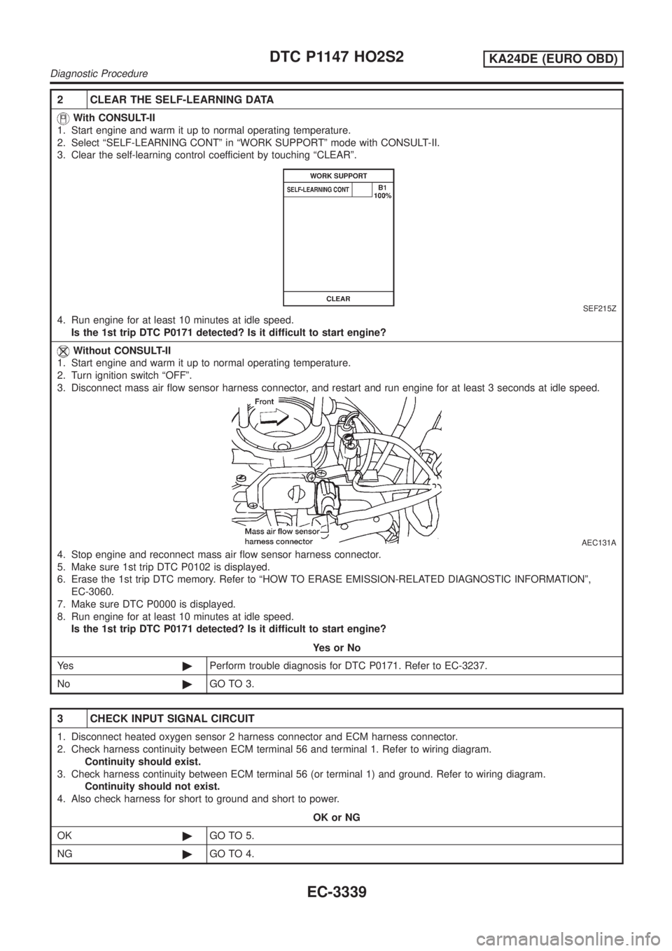
With CONSULT-II
1. Start engine and warm it up to normal operating temperature.
2. Select ªSELF-LEARNING CONTº in ªWORK SUPPORTº mode with CONSULT-II.
3. Clear the self-learning control coefficient by touching ªCLEARº.
SEF215Z
4. Run engine for at least 10 minutes at idle speed.
Is the 1st trip DTC P0171 detected? Is it difficult to start engine?
Without CONSULT-II
1. Start engine and warm it up to normal operating temperature.
2. Turn ignition switch ªOFFº.
3. Disconnect mass air flow sensor harness connector, and restart and run engine for at least 3 seconds at idle speed.
AEC131A
4. Stop engine and reconnect mass air flow sensor harness connector.
5. Make sure 1st trip DTC P0102 is displayed.
6. Erase the 1st trip DTC memory. Refer to ªHOW TO ERASE EMISSION-RELATED DIAGNOSTIC INFORMATIONº,
EC-3060.
7. Make sure DTC P0000 is displayed.
8. Run engine for at least 10 minutes at idle speed.
Is the 1st trip DTC P0171 detected? Is it difficult to start engine?
YesorNo
Ye s©Perform trouble diagnosis for DTC P0171. Refer to EC-3237.
No©GO TO 3.
3 CHECK INPUT SIGNAL CIRCUIT
1. Disconnect heated oxygen sensor 2 harness connector and ECM harness connector.
2. Check harness continuity between ECM terminal 56 and terminal 1. Refer to wiring diagram.
Continuity should exist.
3. Check harness continuity between ECM terminal 56 (or terminal 1) and ground. Refer to wiring diagram.
Continuity should not exist.
4. Also check harness for short to ground and short to power.
OK or NG
OK©GO TO 5.
NG©GO TO 4.
DTC P1147 HO2S2KA24DE (EURO OBD)
Diagnostic Procedure
EC-3339
Page 365 of 1306
4 DETECT MALFUNCTIONING PART
Check the following.
+Harness for open or short between ECM and heated oxygen sensor 2
©Repair open circuit or short to ground or short to power in harness or connectors.
5 CHECK GROUND CIRCUIT
1. Check harness continuity between heated oxygen sensor 2 terminal 4 and engine ground. Refer to Wiring Diagram.
Continuity should exist.
2. Also check harness for short to power.
OK or NG
OK (With CONSULT-II)©GO TO 7.
OK (Without CONSULT-
II)©GO TO 8.
NG©GO TO 6.
6 DETECT MALFUNCTIONING PART
Check the following.
+Joint connector-3
+Harness for open or short between heated oxygen sensor 2 and engine ground
©Repair open circuit or short to power in harness or connectors.
DTC P1147 HO2S2KA24DE (EURO OBD)
Diagnostic Procedure
EC-3340
Page 366 of 1306
7 CHECK HEATED OXYGEN SENSOR 2
With CONSULT-II
1. Reconnect all harness connectors disconnected.
2. Start engine and drive vehicle at a speed of more than 70 km/h (43 MPH) for 2 consecutive minutes.
3. Stop vehicle with engine running.
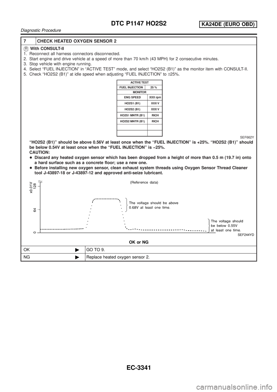
4. Select ªFUEL INJECTIONº in ªACTIVE TESTº mode, and select ªHO2S2 (B1)º as the monitor item with CONSULT-II.
5. Check ªHO2S2 (B1)º at idle speed when adjusting ªFUEL INJECTIONº to±25%.
SEF662Y
ªHO2S2 (B1)º should be above 0.56V at least once when the ªFUEL INJECTIONº is +25%. ªHO2S2 (B1)º should
be below 0.54V at least once when the ªFUEL INJECTIONº is þ25%.
CAUTION:
+Discard any heated oxygen sensor which has been dropped from a height of more than 0.5 m (19.7 in) onto
a hard surface such as a concrete floor; use a new one.
+Before installing new oxygen sensor, clean exhaust system threads using Oxygen Sensor Thread Cleaner
tool J-43897-18 or J-43897-12 and approved anti-seize lubricant.
SEF244YD
OK or NG
OK©GO TO 9.
NG©Replace heated oxygen sensor 2.
DTC P1147 HO2S2KA24DE (EURO OBD)
Diagnostic Procedure
EC-3341
Page 367 of 1306
8 CHECK HEATED OXYGEN SENSOR 2
Without CONSULT-II
1. Reconnect all harness connectors disconnected.
2. Start engine and drive vehicle at a speed of more than 70 km/h (43 MPH) for 2 consecutive minutes.
3. Stop vehicle with engine running.
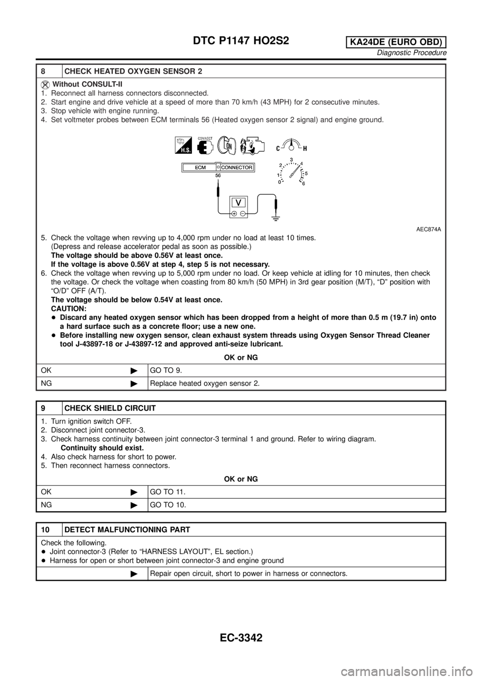
4. Set voltmeter probes between ECM terminals 56 (Heated oxygen sensor 2 signal) and engine ground.
AEC874A
5. Check the voltage when revving up to 4,000 rpm under no load at least 10 times.
(Depress and release accelerator pedal as soon as possible.)
The voltage should be above 0.56V at least once.
If the voltage is above 0.56V at step 4, step 5 is not necessary.
6. Check the voltage when revving up to 5,000 rpm under no load. Or keep vehicle at idling for 10 minutes, then check
the voltage. Or check the voltage when coasting from 80 km/h (50 MPH) in 3rd gear position (M/T), ªDº position with
ªO/Dº OFF (A/T).
The voltage should be below 0.54V at least once.
CAUTION:
+Discard any heated oxygen sensor which has been dropped from a height of more than 0.5 m (19.7 in) onto
a hard surface such as a concrete floor; use a new one.
+Before installing new oxygen sensor, clean exhaust system threads using Oxygen Sensor Thread Cleaner
tool J-43897-18 or J-43897-12 and approved anti-seize lubricant.
OK or NG
OK©GO TO 9.
NG©Replace heated oxygen sensor 2.
9 CHECK SHIELD CIRCUIT
1. Turn ignition switch OFF.
2. Disconnect joint connector-3.
3. Check harness continuity between joint connector-3 terminal 1 and ground. Refer to wiring diagram.
Continuity should exist.
4. Also check harness for short to power.
5. Then reconnect harness connectors.
OK or NG
OK©GO TO 11.
NG©GO TO 10.
10 DETECT MALFUNCTIONING PART
Check the following.
+Joint connector-3 (Refer to ªHARNESS LAYOUTº, EL section.)
+Harness for open or short between joint connector-3 and engine ground
©Repair open circuit, short to power in harness or connectors.
DTC P1147 HO2S2KA24DE (EURO OBD)
Diagnostic Procedure
EC-3342
Page 369 of 1306
On Board Diagnosis LogicNEEC1534If the cooling fan or another component in the cooling system malfunctions, engine coolant temperature will
rise.
When the engine coolant temperature reaches an abnormally high temperature condition, a malfunction is
indicated.
DTC No. Malfunction is detected when ...Check Items
(Possible Cause)
P1217
1217+Engine coolant temperature reaches an abnormally high
temperature.+Cooling fan (crankshaft driven)
Radiator hose
+Radiator
+Radiator cap
+Water pump
+Thermostat
+Engine coolant temperature sensor
For more information, refer to ªMAIN 11 CAUSES
OF OVERHEATINGº, EC-3348.
CAUTION:
When a malfunction is indicated, be sure to replace the coolant. Refer to MA section, ªChanging Engine
Coolantº. Also, replace the engine oil.
1) Fill radiator with coolant up to specified level with a filling speed of 2 liters per minute. Be sure
to use coolant with the proper mixture ratio. Refer to MA section, ªAnti-freeze Coolant Mixture
Ratioº.
2) After refilling coolant, run engine to ensure that no water-flow noise is emitted.
SEF621W
Overall Function CheckNEEC1535WARNING:
Never remove the radiator cap when the engine is hot. Serious
burns could be caused by high pressure fluid escaping from
the radiator.
Wrap a thick cloth around cap. Carefully remove the cap by
turning it a quarter turn to allow built-up pressure to escape.
Then turn the cap all the way off.
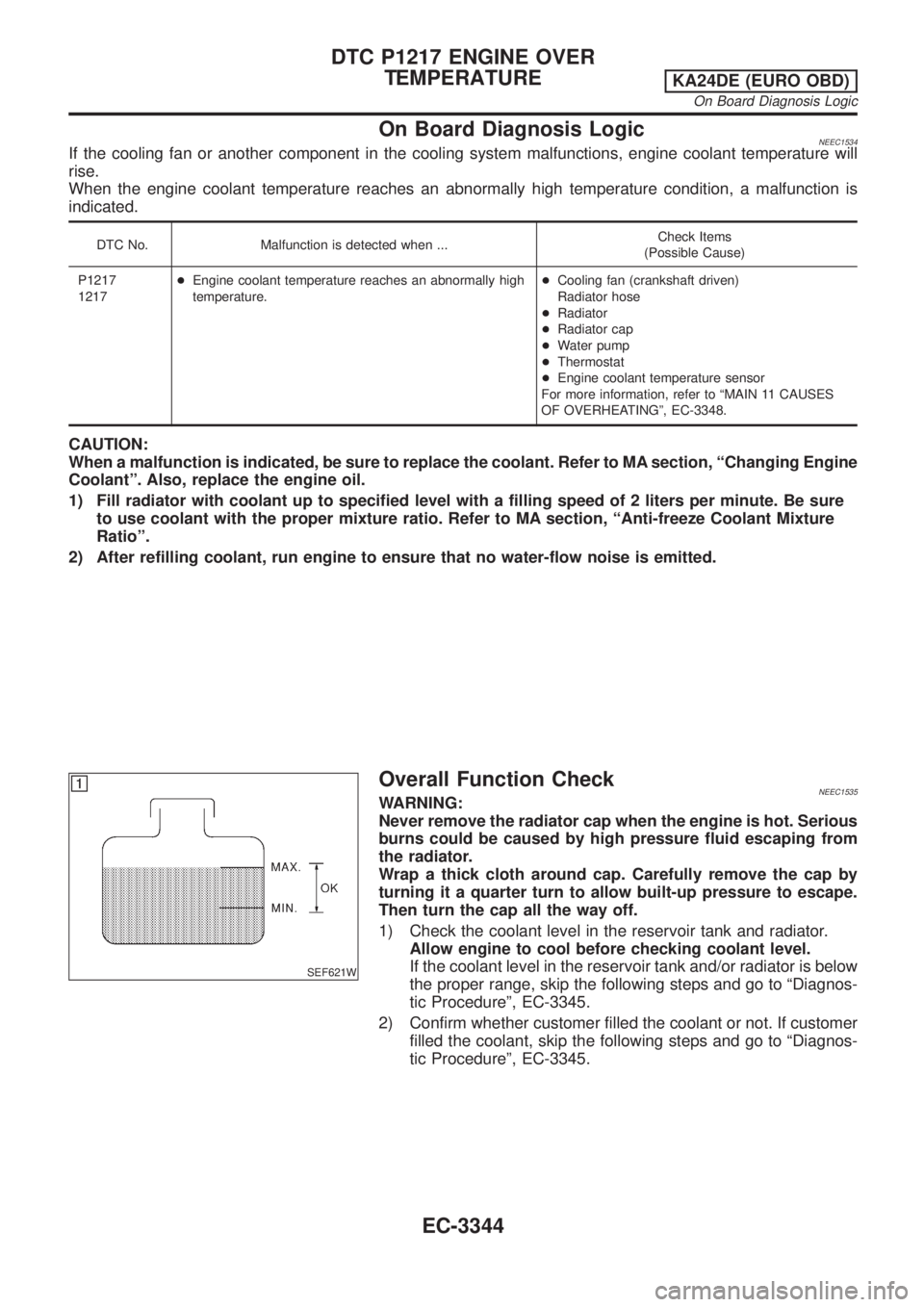
1) Check the coolant level in the reservoir tank and radiator.
Allow engine to cool before checking coolant level.
If the coolant level in the reservoir tank and/or radiator is below
the proper range, skip the following steps and go to ªDiagnos-
tic Procedureº, EC-3345.
2) Confirm whether customer filled the coolant or not. If customer
filled the coolant, skip the following steps and go to ªDiagnos-
tic Procedureº, EC-3345.
DTC P1217 ENGINE OVER
TEMPERATURE
KA24DE (EURO OBD)
On Board Diagnosis Logic
EC-3344
Page 372 of 1306
4 CHECK ENGINE COOLANT TEMPERATURE SENSOR
Check resistance as shown in the figure.
SEF152P
MTBL0285
SEF012P
OK or NG
OK©GO TO 5.
NG©Replace engine coolant temperature sensor.
5 CHECK MAIN 11 CAUSES
If the cause cannot be isolated, go to ªMAIN 11 CAUSES OF OVERHEATINGº, EC-3348.
©INSPECTION END
Perform FINAL CHECK by the following procedure after repair
is completed.
1. Warm up engine. Run the vehicle for at least 20 minutes. Pay
attention to engine coolant temperature gauge on the instru-
ment panel. If the reading shows an abnormally high
temperature, another part may be malfunctioning.
2. Stop vehicle and let engine idle. Check the intake and exhaust
systems for leaks by listening for noise or visually inspecting
the components.
3. Allow engine to cool and visually check for oil and coolant
leaks. Then, perform ªOVERALL FUNCTION CHECKº.
DTC P1217 ENGINE OVER
TEMPERATURE
KA24DE (EURO OBD)
Diagnostic Procedure
EC-3347
Page 374 of 1306
SEF956N
SEF335V
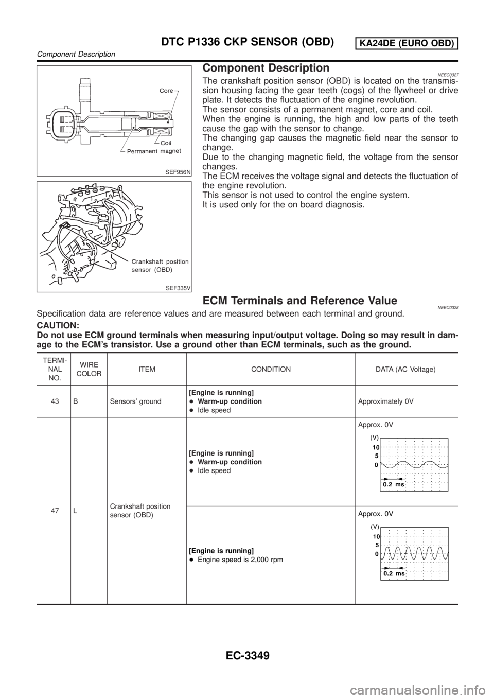
Component DescriptionNEEC0327The crankshaft position sensor (OBD) is located on the transmis-
sion housing facing the gear teeth (cogs) of the flywheel or drive
plate. It detects the fluctuation of the engine revolution.
The sensor consists of a permanent magnet, core and coil.
When the engine is running, the high and low parts of the teeth
cause the gap with the sensor to change.
The changing gap causes the magnetic field near the sensor to
change.
Due to the changing magnetic field, the voltage from the sensor
changes.
The ECM receives the voltage signal and detects the fluctuation of
the engine revolution.
This sensor is not used to control the engine system.
It is used only for the on board diagnosis.
ECM Terminals and Reference ValueNEEC0328Specification data are reference values and are measured between each terminal and ground.
CAUTION:
Do not use ECM ground terminals when measuring input/output voltage. Doing so may result in dam-
age to the ECM's transistor. Use a ground other than ECM terminals, such as the ground.
TERMI-
NAL
NO.WIRE
COLORITEM CONDITION DATA (AC Voltage)
43 B Sensors' ground[Engine is running]
+Warm-up condition
+Idle speedApproximately 0V
47 LCrankshaft position
sensor (OBD)[Engine is running]
+Warm-up condition
+Idle speedApprox. 0V
[Engine is running]
+Engine speed is 2,000 rpmApprox. 0V
DTC P1336 CKP SENSOR (OBD)KA24DE (EURO OBD)
Component Description
EC-3349
Page 375 of 1306
On Board Diagnosis LogicNEEC0329
DTC No. Malfunction is detected when ... Check Items (Possible Cause)
P1336
1336+A chipping of the flywheel or drive plate gear tooth (cog)
is detected by the ECM.+Harness or connectors
+Crankshaft position sensor (OBD)
+Flywheel
SEF058Y
DTC Confirmation ProcedureNEEC0330NOTE:
If ªDTC Confirmation Procedureº has been previously conducted,
always turn ignition switch OFF and wait at least 5 seconds before
conducting the next test.
With CONSULT-II
1) Turn ignition switch ON and select ªDATA MONITORº mode
with CONSULT-II.
2) Start engine and run it for at least 2 minutes at idle speed.
3) If 1st trip DTC is detected, go to ªDiagnostic Procedureº,
EC-3352.
With GST
Follow the procedure ªWith CONSULT-IIº.
DTC P1336 CKP SENSOR (OBD)KA24DE (EURO OBD)
On Board Diagnosis Logic
EC-3350