Page 457 of 1306
Diagnostic test mode I Ð Bulb check
In this mode, the MIL on the instrument panel should stay ON. If it remains OFF, check the bulb. Refer to
EL section, ªWARNING LAMPS AND CHIMEº or see EC-3647.
Diagnostic test mode I Ð Malfunction warning
MIL Condition
ON When the malfunction is detected or the ECM's CPU is malfunctioning.
OFF No malfunction.
Diagnostic test mode II Ð Self-diagnostic results
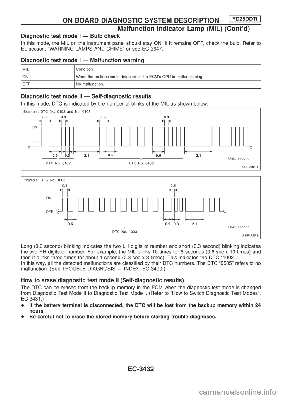
In this mode, DTC is indicated by the number of blinks of the MIL as shown below.
Long (0.6 second) blinking indicates the two LH digits of number and short (0.3 second) blinking indicates
the two RH digits of number. For example, the MIL blinks 10 times for 6 seconds (0.6 sec x 10 times) and
then it blinks three times for about 1 second (0.3 sec x 3 times). This indicates the DTC ª1003º.
In this way, all the detected malfunctions are classified by their DTC numbers. The DTC ª0505º refers to no
malfunction. (See TROUBLE DIAGNOSIS Ð INDEX, EC-3400.)
How to erase diagnostic test mode II (Self-diagnostic results)
The DTC can be erased from the backup memory in the ECM when the diagnostic test mode is changed
from Diagnostic Test Mode II to Diagnostic Test Mode I. (Refer to ªHow to Switch Diagnostic Test Modesº,
EC-3431.)
+If the battery terminal is disconnected, the DTC will be lost from the backup memory within 24
hours.
+Be careful not to erase the stored memory before starting trouble diagnoses.
SEF298QA
SEF162PB
ON BOARD DIAGNOSTIC SYSTEM DESCRIPTIONYD25DDTi
Malfunction Indicator Lamp (MIL) (Cont'd)
EC-3432
Page 488 of 1306
ECM Terminals and Reference Value
PREPARATION
1. ECM is located behind the instrument lower panel. For this
inspection, remove the driver's side instrument lower cover.
2. Remove ECM harness protector.
3. Perform all voltage measurements with the connector con-
nected. Extend tester probe as shown to perform tests eas-
ily.
+Open harness securing clip to make testing easier.
+Use extreme care not to touch 2 pins at one time.
+Data is for comparison and may not be exact.
Be sure ECM unit is properly grounded before checking.
SEC948C
AEC913
SEF367I
SEF665S
TROUBLE DIAGNOSIS Ð GENERAL DESCRIPTIONYD25DDTi
EC-3463
Page 663 of 1306
Component Description
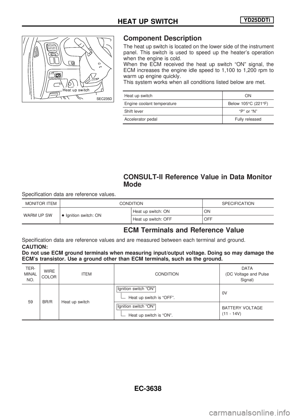
The heat up switch is located on the lower side of the instrument
panel. This switch is used to speed up the heater's operation
when the engine is cold.
When the ECM received the heat up switch ªONº signal, the
ECM increases the engine idle speed to 1,100 to 1,200 rpm to
warm up engine quickly.
This system works when all conditions listed below are met.
Heat up switch ON
Engine coolant temperature Below 105ÉC (221ÉF)
Shift lever ªPº or ªNº
Accelerator pedal Fully released
CONSULT-II Reference Value in Data Monitor
Mode
Specification data are reference values.
MONITOR ITEM CONDITION SPECIFICATION
WARM UP SW+Ignition switch: ONHeat up switch: ON ON
Heat up switch: OFF OFF
ECM Terminals and Reference Value
Specification data are reference values and are measured between each terminal and ground.
CAUTION:
Do not use ECM ground terminals when measuring input/output voltage. Doing so may damage the
ECM's transistor. Use a ground other than ECM terminals, such as the ground.
TER-
MINAL
NO.WIRE
COLORITEM CONDITIONDATA
(DC Voltage and Pulse
Signal)
59 BR/R Heat up switchIgnition switch ªONº
Heat up switch is ªOFFº.0V
Ignition switch ªONº
Heat up switch is ªONº.BATTERY VOLTAGE
(11 - 14V)
SEC235D
HEAT UP SWITCHYD25DDTi
EC-3638
Page 679 of 1306
Supplemental Restraint System (SRS) ªAIR
BAGº and ªSEAT BELT PRE-TENSIONERº
The Supplemental Restraint System such as ªAIR BAGº and ªSEAT BELT PRE-TENSIONERº used along
with a seat belt, helps to reduce the risk or severity of injury to the driver and front passenger in a frontal
collision. The SRS system composition which is available to NISSAN MODEL D22 is as follows (The com-
position varies according to the destination and optional equipment.):
Driver air bag module (located in the center of the steering wheel), front passenger air bag module (located
on the instrument panel on passenger side), seat belt pre-tensioner, a diagnosis sensor unit, warning lamp,
wiring harness and spiral cable.
Information necessary to service the system safely is included in theRS sectionof this Service Manual.
WARNING:
+To avoid rendering the SRS inoperative, which could increase the risk of personal injury or death
in the event of a collision which would result in air bag inflation, all maintenance must be per-
formed by an authorized NISSAN dealer.
+Improper maintenance, including incorrect removal and installation of the SRS, can lead to per-
sonal injury caused by unintentional activation of the system. For removal of Spiral Cable and
Air Bag Module, see the RS section.
+Do not use electrical test equipment on any circuit related to the SRS unless instructed to in this
Service Manual. SRS wiring harnesses can be identified by yellow harness connector.
PRECAUTIONS
EL-3004
Page 839 of 1306
Main Harness
INSTRUMENT PANEL Ð LHD MODELS
HEL851B
HARNESS LAYOUT
EL-3164
Page 841 of 1306
INSTRUMENT PANEL Ð RHD MODELS
HEL853B
HARNESS LAYOUT
Main Harness (Cont'd)
EL-3166
Page 1073 of 1306
Supplemental Restraint System (SRS) ªAIR
BAGº and ªSEAT BELT PRE-TENSIONERº
The Supplemental Restraint System such as ªAIR BAGº and ªSEAT BELT PRE-TENSIONERº used along
with a seat belt, helps to reduce the risk or severity of injury to the driver and front passenger in a frontal
collision. The SRS composition which is available to NISSAN MODEL D22 is as follows (The composition
varies according to the destination and optional equipment.):
Driver air bag module (located in the center of the steering wheel), front passenger air bag module (located
on the instrument panel on passenger side), seat belt pre-tensioner, a diagnosis sensor unit, warning lamp,
wiring harness and spiral cable.
WARNING:
+To avoid rendering the SRS inoperative, which could increase the risk of personal injury or death
in the event of a collision which would result in air bag inflation, all maintenance must be per-
formed by an authorized NISSAN dealer.
+Improper maintenance, including incorrect removal and installation of the SRS, can lead to per-
sonal injury caused by unintentional activation of the system.
+Do not use electrical test equipment on any circuit related to the SRS unless instructed to in this
Service Manual. SRS wiring harnesses can be identified by yellow harness connector.
PRECAUTION
RS-3002
Page 1074 of 1306
Precautions for SRS ªAIR BAGº and ªSEAT
BELT PRE-TENSIONERº Service
+Do not use electrical test equipment to check SRS circuits unless instructed to in this Service Manual.
+Before servicing the SRS, turn ignition switch ªOFFº, disconnect battery ground cable and wait at least 3
minutes.
For approximately 3 minutes after the cables are removed, it is still possible for the air bag and seat belt
pre-tensioner to deploy. Therefore, do not work on any SRS connectors or wires until at least 3 minutes have
passed.
+Diagnosis sensor unit must always be installed with their arrow marks ª
Sº pointing towards the front of
the vehicle for proper operation. Also check diagnosis sensor unit for cracks, deformities or rust before
installation and replace as required.
+The spiral cable must be aligned with the neutral position since its rotations are limited. Do not attempt
to turn steering wheel or column after removal of steering gear.
+Handle air bag module carefully. Always place driver and passenger air bag modules with the pad side
facing upward.
+Conduct self-diagnosis to check entire SRS for proper function after replacing any components.
+After air bag inflates, the front instrument panel assembly should be replaced if damaged.
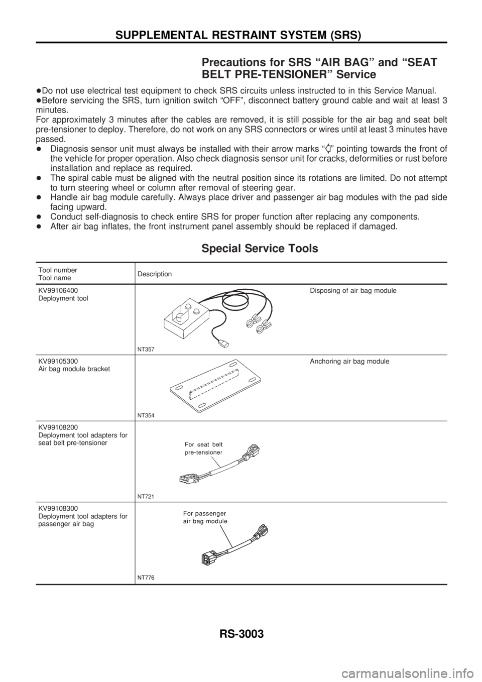
Special Service Tools
Tool number
Tool nameDescription
KV99106400
Deployment tool
NT357
Disposing of air bag module
KV99105300
Air bag module bracket
NT354
Anchoring air bag module
KV99108200
Deployment tool adapters for
seat belt pre-tensioner
NT721
KV99108300
Deployment tool adapters for
passenger air bag
NT776
SUPPLEMENTAL RESTRAINT SYSTEM (SRS)
RS-3003