Page 1242 of 1306

Trouble Diagnoses/With Interruption
Detection Function
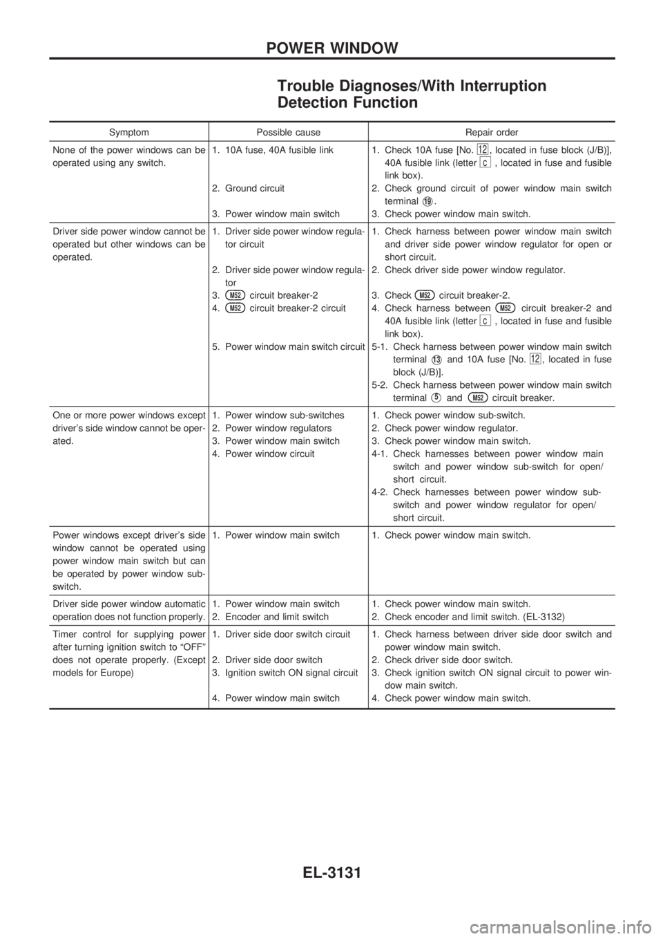
Symptom Possible cause Repair order
None of the power windows can be
operated using any switch.1. 10A fuse, 40A fusible link
2. Ground circuit
3. Power window main switch1. Check 10A fuse [No.
12, located in fuse block (J/B)],
40A fusible link (letter
c, located in fuse and fusible
link box).
2. Check ground circuit of power window main switch
terminal
V19.
3. Check power window main switch.
Driver side power window cannot be
operated but other windows can be
operated.1. Driver side power window regula-
tor circuit
2. Driver side power window regula-
tor
3.
M52circuit breaker-2
4.
M52circuit breaker-2 circuit
5. Power window main switch circuit1. Check harness between power window main switch
and driver side power window regulator for open or
short circuit.
2. Check driver side power window regulator.
3. Check
M52circuit breaker-2.
4. Check harness between
M52circuit breaker-2 and
40A fusible link (letter
c, located in fuse and fusible
link box).
5-1. Check harness between power window main switch
terminal
V13and 10A fuse [No.12, located in fuse
block (J/B)].
5-2. Check harness between power window main switch
terminal
V5andM52circuit breaker.
One or more power windows except
driver's side window cannot be oper-
ated.1. Power window sub-switches
2. Power window regulators
3. Power window main switch
4. Power window circuit1. Check power window sub-switch.
2. Check power window regulator.
3. Check power window main switch.
4-1. Check harnesses between power window main
switch and power window sub-switch for open/
short circuit.
4-2. Check harnesses between power window sub-
switch and power window regulator for open/
short circuit.
Power windows except driver's side
window cannot be operated using
power window main switch but can
be operated by power window sub-
switch.1. Power window main switch 1. Check power window main switch.
Driver side power window automatic
operation does not function properly.1. Power window main switch
2. Encoder and limit switch1. Check power window main switch.
2. Check encoder and limit switch. (EL-3132)
Timer control for supplying power
after turning ignition switch to ªOFFº
does not operate properly. (Except
models for Europe)1. Driver side door switch circuit
2. Driver side door switch
3. Ignition switch ON signal circuit
4. Power window main switch1. Check harness between driver side door switch and
power window main switch.
2. Check driver side door switch.
3. Check ignition switch ON signal circuit to power win-
dow main switch.
4. Check power window main switch.
POWER WINDOW
EL-3131
Page 1258 of 1306
CONSULT-II
CONSULT-II INSPECTION PROCEDURE
1. Turn ignition switch OFF.
2. Insert NATS program card into CONSULT-II.
Program card
AEN00A/B
3. Connect CONSULT-II to Data link connector which is located
behind the fuse box cover.
4. Turn ignition switch ON.
5. Touch ªSTARTº.
6. Perform each diagnostic test mode according to each service
procedure.
For further information, see the CONSULT-II Operation
Manual, NATS.
SEL595Y
SEL617Y
SEL150X
NATS (Nissan Anti-Theft System)
EL-3147
Page 1264 of 1306

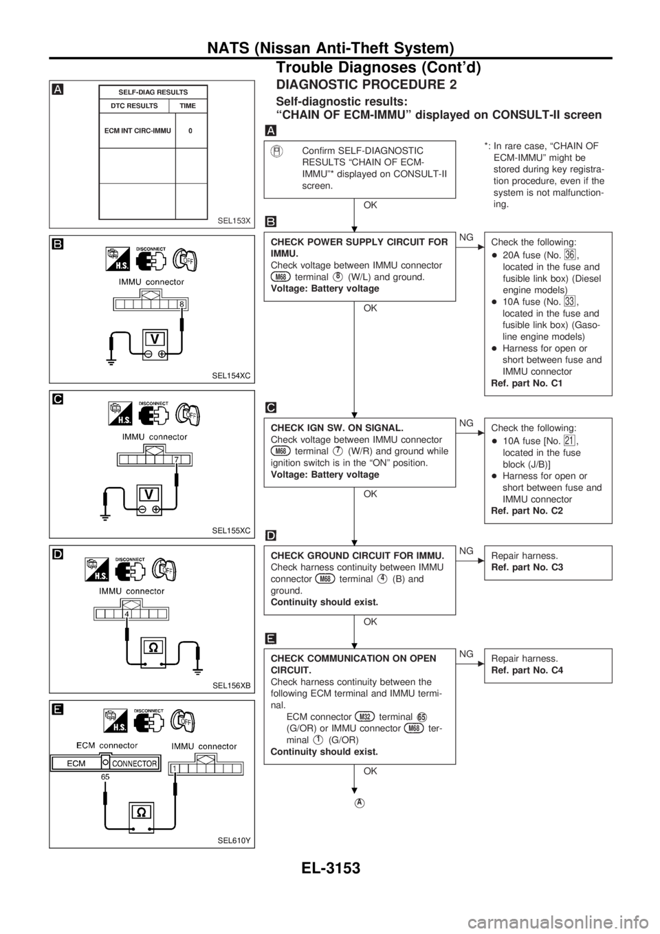
DIAGNOSTIC PROCEDURE 2
Self-diagnostic results:
ªCHAIN OF ECM-IMMUº displayed on CONSULT-II screen
Confirm SELF-DIAGNOSTIC
RESULTS ªCHAIN OF ECM-
IMMUº* displayed on CONSULT-II
screen.
OK*: In rare case, ªCHAIN OF
ECM-IMMUº might be
stored during key registra-
tion procedure, even if the
system is not malfunction-
ing.
CHECK POWER SUPPLY CIRCUIT FOR
IMMU.
Check voltage between IMMU connector
M68terminalV8(W/L) and ground.
Voltage: Battery voltage
OK
cNG
Check the following:
+20A fuse (No.
36,
located in the fuse and
fusible link box) (Diesel
engine models)
+10A fuse (No.
33,
located in the fuse and
fusible link box) (Gaso-
line engine models)
+Harness for open or
short between fuse and
IMMU connector
Ref. part No. C1
CHECK IGN SW. ON SIGNAL.
Check voltage between IMMU connector
M68terminalV7(W/R) and ground while
ignition switch is in the ªONº position.
Voltage: Battery voltage
OK
cNG
Check the following:
+10A fuse [No.
21,
located in the fuse
block (J/B)]
+Harness for open or
short between fuse and
IMMU connector
Ref. part No. C2
CHECK GROUND CIRCUIT FOR IMMU.
Check harness continuity between IMMU
connector
M68terminalV4(B) and
ground.
Continuity should exist.
OK
cNG
Repair harness.
Ref. part No. C3
CHECK COMMUNICATION ON OPEN
CIRCUIT.
Check harness continuity between the
following ECM terminal and IMMU termi-
nal.
ECM connector
M32terminalV65
(G/OR) or IMMU connectorM68ter-
minal
V1(G/OR)
Continuity should exist.
OK
cNG
Repair harness.
Ref. part No. C4
VA
SEL153X
SEL154XC
SEL155XC
SEL156XB
SEL610Y
.
.
.
.
.
NATS (Nissan Anti-Theft System)
Trouble Diagnoses (Cont'd)
EL-3153