2001 NISSAN PICK-UP change time
[x] Cancel search: change timePage 2 of 1306
FOREWORD
This manual contains maintenance and repair procedures for NISSAN
PICKUP, model D22 series.
In order to assure your safety and the efficient functioning of the vehicle,
this manual should be read thoroughly. It is especially important that the
PRECAUTIONS in the GI section be completely understood before starting
any repair task.
All information in this manual is based on the latest product information
at the time of publication. The right is reserved to make changes in speci-
®cations and methods at any time without notice.
IMPORTANT SAFETY NOTICE
The proper performance of service is essential for both the safety of the
technician and the efficient functioning of the vehicle.
The service methods in this Service Manual are described in such a man-
ner that the service may be performed safely and accurately.
Service varies with the procedures used, the skills of the technician and the
tools and parts available. Accordingly, anyone using service procedures,
tools or parts which are not speci®cally recommended by NISSAN must
®rst completely satisfy himself that neither his safety nor the vehicle's
safety will be jeopardized by the service method selected.
NISSAN EUROPE S.A.S.
Service Engineering Section
Paris, France
Page 50 of 1306

Mixture Ratio Feedback Control (Closed loop control)NEEC0014S04
SEC303D
The mixture ratio feedback system provides the best air-fuel mixture ratio for driveability and emission con-
trol. The three way catalyst can then better reduce CO, HC and NOx emissions. This system uses a heated
oxygen sensor 1 in the exhaust manifold to monitor if the engine operation is rich or lean. The ECM adjusts
the injection pulse width according to the sensor voltage signal. For more information about the heated oxy-
gen sensor 1, refer to EC-3213. This maintains the mixture ratio within the range of stoichiometric (ideal air-
fuel mixture).
This stage is referred to as the closed loop control condition.
Heated oxygen sensor 2 is located downstream of the three way catalyst. Even if the switching characteris-
tics of the heated oxygen sensor 1 shift, the air-fuel ratio is controlled to stoichiometric by the signal from the
heated oxygen sensor 2.
Open Loop ControlNEEC0014S05The open loop system condition refers to when the ECM detects any of the following conditions. Feedback
control stops in order to maintain stabilized fuel combustion.
+Deceleration and acceleration
+High-load, high-speed operation
+Malfunction of heated oxygen sensor 1 or its circuit
+Insufficient activation of heated oxygen sensor 1 at low engine coolant temperature
+High engine coolant temperature
+During warm-up
+When starting the engine
Mixture Ratio Self-learning ControlNEEC0014S06The mixture ratio feedback control system monitors the mixture ratio signal transmitted from the heated oxy-
gen sensor 1. This feedback signal is then sent to the ECM. The ECM controls the basic mixture ratio as close
to the theoretical mixture ratio as possible. However, the basic mixture ratio is not necessarily controlled as
originally designed. Both manufacturing differences (i.e., mass air flow sensor hot film) and characteristic
changes during operation (i.e., injector clogging) directly affect mixture ratio.
Accordingly, the difference between the basic and theoretical mixture ratios is monitored in this system. This
is then computed in terms of ªinjection pulse durationº to automatically compensate for the difference between
the two ratios.
ªFuel trimº refers to the feedback compensation value compared against the basic injection duration. Fuel trim
includes short term fuel trim and long term fuel trim.
ªShort term fuel trimº is the short-term fuel compensation used to maintain the mixture ratio at its theoretical
value. The signal from the heated oxygen sensor 1 indicates whether the mixture ratio is RICH or LEAN com-
pared to the theoretical value. The signal then triggers a reduction in fuel volume if the mixture ratio is rich,
and an increase in fuel volume if it is lean.
ªLong term fuel trimº is overall fuel compensation carried out long-term to compensate for continual deviation
of the short term fuel trim from the central value. Such deviation will occur due to individual engine differences,
wear over time and changes in the usage environment.
ENGINE AND EMISSION BASIC CONTROL SYSTEM
DESCRIPTION
KA24DE (EURO OBD)
Multiport Fuel Injection (MFI) System
EC-3025
Page 76 of 1306
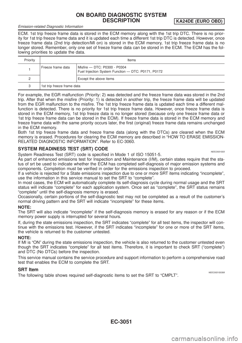
ECM. 1st trip freeze frame data is stored in the ECM memory along with the 1st trip DTC. There is no prior-
ity for 1st trip freeze frame data and it is updated each time a different 1st trip DTC is detected. However, once
freeze frame data (2nd trip detection/MI on) is stored in the ECM memory, 1st trip freeze frame data is no
longer stored. Remember, only one set of freeze frame data can be stored in the ECM. The ECM has the fol-
lowing priorities to update the data.
Priority Items
1Freeze frame data Misfire Ð DTC: P0300 - P0304
Fuel Injection System Function Ð DTC: P0171, P0172
2 Except the above items
3 1st trip freeze frame data
For example, the EGR malfunction (Priority: 2) was detected and the freeze frame data was stored in the 2nd
trip. After that when the misfire (Priority: 1) is detected in another trip, the freeze frame data will be updated
from the EGR malfunction to the misfire. The 1st trip freeze frame data is updated each time a different mal-
function is detected. There is no priority for 1st trip freeze frame data. However, once freeze frame data is
stored in the ECM memory, 1st trip freeze data is no longer stored (because only one freeze frame data or
1st trip freeze frame data can be stored in the ECM). If freeze frame data is stored in the ECM memory and
freeze frame data with the same priority occurs later, the first (original) freeze frame data remains unchanged
in the ECM memory.
Both 1st trip freeze frame data and freeze frame data (along with the DTCs) are cleared when the ECM
memory is erased. Procedures for clearing the ECM memory are described in ªHOW TO ERASE EMISSION-
RELATED DIAGNOSTIC INFORMATIONº. Refer to EC-3060.
SYSTEM READINESS TEST (SRT) CODENEEC0031S03System Readiness Test (SRT) code is specified in Mode 1 of ISO 15051-5.
As part of enhanced emissions test for Inspection and Maintenance (I/M), certain states require that the sta-
tus of srt be used to indicate whether the ECM has completed self-diagnosis of major emission systems and
components. Completion must be verified in order for the emissions inspection to proceed.
If a vehicle is rejected for a State emissions inspection due to one or more SRT items indicating ªincompleteº,
use the information in this service manual to set the SRT to ªcompleteº.
In most cases, the ECM will automatically complete its self-diagnosis cycle during normal usage and the SRT
status will indicate ªcompleteº for each application system. Once set as ªcompleteº, the SRT status remains
ªcompleteº until the self-diagnosis memory is erased.
Occasionally, certain portions of the self-diagnostic test may not be completed as a result of the customer's
normal driving pattern and the SRT will indicate ªincompleteº for these items.
NOTE:
The SRT will also indicate ªincompleteº if the self-diagnosis memory is erased for any reason or if the ECM
memory power supply is interrupted for several hours.
If, during the state emissions inspection, the SRT indicates ªcompleteº for all test items, the inspector will con-
tinue with the emissions test. However, if the SRT indicates ªincompleteº for one or more of the SRT items,
the vehicle is returned to the customer untested.
NOTE:
If MI is ªONº during the state emissions inspection, the vehicle is also returned to the customer untested even
though the SRT indicates ªcompleteº for all test items. Therefore, it is important to check SRT (ªcompleteº)
and DTC (No DTCs) before the inspection.
This service manual contains the service procedure and support information to perform a comprehensive road
test that enables the ECM to complete the SRT.
SRT ItemNEEC0031S0308The following table shows required self-diagnostic items to set the SRT to ªCMPLTº.
ON BOARD DIAGNOSTIC SYSTEM
DESCRIPTION
KA24DE (EURO OBD)
Emission-related Diagnostic Information
EC-3051
Page 82 of 1306
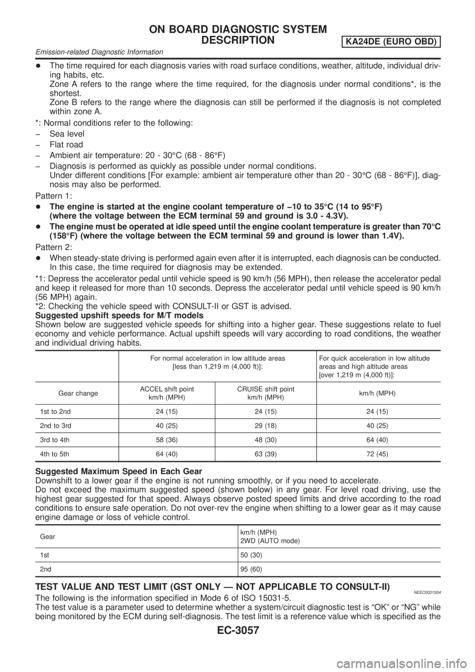
+The time required for each diagnosis varies with road surface conditions, weather, altitude, individual driv-
ing habits, etc.
Zone A refers to the range where the time required, for the diagnosis under normal conditions*, is the
shortest.
Zone B refers to the range where the diagnosis can still be performed if the diagnosis is not completed
within zone A.
*: Normal conditions refer to the following:
þ Sea level
þ Flat road
þ Ambient air temperature: 20 - 30ÉC (68 - 86ÉF)
þ Diagnosis is performed as quickly as possible under normal conditions.
Under different conditions [For example: ambient air temperature other than 20 - 30ÉC (68 - 86ÉF)], diag-
nosis may also be performed.
Pattern 1:
+The engine is started at the engine coolant temperature of þ10 to 35ÉC (14 to 95ÉF)
(where the voltage between the ECM terminal 59 and ground is 3.0 - 4.3V).
+The engine must be operated at idle speed until the engine coolant temperature is greater than 70ÉC
(158ÉF) (where the voltage between the ECM terminal 59 and ground is lower than 1.4V).
Pattern 2:
+When steady-state driving is performed again even after it is interrupted, each diagnosis can be conducted.
In this case, the time required for diagnosis may be extended.
*1: Depress the accelerator pedal until vehicle speed is 90 km/h (56 MPH), then release the accelerator pedal
and keep it released for more than 10 seconds. Depress the accelerator pedal until vehicle speed is 90 km/h
(56 MPH) again.
*2: Checking the vehicle speed with CONSULT-II or GST is advised.
Suggested upshift speeds for M/T models
Shown below are suggested vehicle speeds for shifting into a higher gear. These suggestions relate to fuel
economy and vehicle performance. Actual upshift speeds will vary according to road conditions, the weather
and individual driving habits.
For normal acceleration in low altitude areas
[less than 1,219 m (4,000 ft)]:For quick acceleration in low altitude
areas and high altitude areas
[over 1,219 m (4,000 ft)]:
Gear changeACCEL shift point
km/h (MPH)CRUISE shift point
km/h (MPH)km/h (MPH)
1st to 2nd 24 (15) 24 (15) 24 (15)
2nd to 3rd 40 (25) 29 (18) 40 (25)
3rd to 4th 58 (36) 48 (30) 64 (40)
4th to 5th 64 (40) 63 (39) 72 (45)
Suggested Maximum Speed in Each Gear
Downshift to a lower gear if the engine is not running smoothly, or if you need to accelerate.
Do not exceed the maximum suggested speed (shown below) in any gear. For level road driving, use the
highest gear suggested for that speed. Always observe posted speed limits and drive according to the road
conditions to ensure safe operation. Do not over-rev the engine when shifting to a lower gear as it may cause
engine damage or loss of vehicle control.
Gearkm/h (MPH)
2WD (AUTO mode)
1st 50 (30)
2nd 95 (60)
TEST VALUE AND TEST LIMIT (GST ONLY Ð NOT APPLICABLE TO CONSULT-II)NEEC0031S04The following is the information specified in Mode 6 of ISO 15031-5.
The test value is a parameter used to determine whether a system/circuit diagnostic test is ªOKº or ªNGº while
being monitored by the ECM during self-diagnosis. The test limit is a reference value which is specified as the
ON BOARD DIAGNOSTIC SYSTEM
DESCRIPTION
KA24DE (EURO OBD)
Emission-related Diagnostic Information
EC-3057
Page 89 of 1306

SEC687C
A particular trouble code can be identified by the number of four-digit numeral flashes. The ªzeroº is indicated
by the number of ten flashes. The length of time the 1,000th-digit numeral flashes on and off is 1.2 seconds
consisting of an ON (0.6-second) - OFF (0.6-second) cycle.
The 100th-digit numeral and lower digit numerals consist of a 0.3-second ON and 0.3-second OFF cycle.
A change from one digit numeral to another occurs at an interval of 1.0-second OFF. In other words, the later
numeral appears on the display 1.3 seconds after the former numeral has disappeared.
A change from one trouble code to another occurs at an interval of 1.8-second OFF.
In this way, all the detected malfunctions are classified by their DTC numbers. The DTC ª0000º refers to no
malfunction. (See ªTROUBLE DIAGNOSIS Ð INDEXº, EC-3009.)
How to Erase Diagnostic Test Mode II (Self-diagnostic Results)
NEEC0032S1101The DTC can be erased from the back up memory in the ECM by depressing accelerator pedal. Refer to How
to Switch Diagnostic Test Mode.
+If the battery is disconnected, the DTC will be lost from the backup memory after approx 24 hours.
+Be careful not to erase the stored memory before starting trouble diagnoses.
Diagnostic Test Mode II Ð Heated Oxygen Sensor 1 MonitorNEEC0032S12In this mode, the MI displays the condition of the fuel mixture (lean or rich) which is monitored by the heated
oxygen sensor 1.
MI Fuel mixture condition in the exhaust gas Air fuel ratio feedback control condition
ON Lean
Closed loop system
OFF Rich
*Remains ON or OFF Any condition Open loop system
*: Maintains conditions just before switching to open loop.
To check the heated oxygen sensor 1 function, start engine in the Diagnostic Test Mode II and warm it up until
engine coolant temperature indicator points to the middle of the gauge.
Next run engine at about 2,000 rpm for about 2 minutes under no-load conditions. Then make sure that the
MI comes ON more than 5 times within 10 seconds with engine running at 2,000 rpm under no-load.
OBD System Operation ChartNEEC0033RELATIONSHIP BETWEEN MI, DTC, 1ST TRIP DTC AND DETECTABLE ITEMSNEEC0033S01+When a malfunction is detected for the first time, the 1st trip DTC and the 1st trip freeze frame data are
stored in the ECM memory.
+When the same malfunction is detected in two consecutive trips, the DTC and the freeze frame data are
stored in the ECM memory, and the MI will come on. For details, refer to ªTwo Trip Detection Logicº on
EC-3049.
ON BOARD DIAGNOSTIC SYSTEM
DESCRIPTION
KA24DE (EURO OBD)
Malfunction Indicator (MI)
EC-3064
Page 102 of 1306
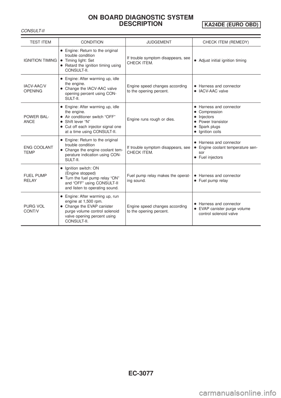
TEST ITEM CONDITION JUDGEMENT CHECK ITEM (REMEDY)
IGNITION TIMING+Engine: Return to the original
trouble condition
+Timing light: Set
+Retard the ignition timing using
CONSULT-II.If trouble symptom disappears, see
CHECK ITEM.+Adjust initial ignition timing
IACV-AAC/V
OPENING+Engine: After warming up, idle
the engine.
+Change the IACV-AAC valve
opening percent using CON-
SULT-II.Engine speed changes according
to the opening percent.+Harness and connector
+IACV-AAC valve
POWER BAL-
ANCE+Engine: After warming up, idle
the engine.
+Air conditioner switch ªOFFº
+Shift lever ªNº
+Cut off each injector signal one
at a time using CONSULT-II.Engine runs rough or dies.+Harness and connector
+Compression
+Injectors
+Power transistor
+Spark plugs
+Ignition coils
ENG COOLANT
TEMP+Engine: Return to the original
trouble condition
+Change the engine coolant tem-
perature indication using CON-
SULT-II.If trouble symptom disappears, see
CHECK ITEM.+Harness and connector
+Engine coolant temperature sen-
sor
+Fuel injectors
FUEL PUMP
RELAY+Ignition switch: ON
(Engine stopped)
+Turn the fuel pump relay ªONº
and ªOFFº using CONSULT-II
and listen to operating sound.Fuel pump relay makes the operat-
ing sound.+Harness and connector
+Fuel pump relay
PURG VOL
CONT/V+Engine: After warming up, run
engine at 1,500 rpm.
+Change the EVAP canister
purge volume control solenoid
valve opening percent using
CONSULT-II.Engine speed changes according
to the opening percent.+Harness and connector
+EVAP canister purge volume
control solenoid valve
ON BOARD DIAGNOSTIC SYSTEM
DESCRIPTION
KA24DE (EURO OBD)
CONSULT-II
EC-3077
Page 103 of 1306
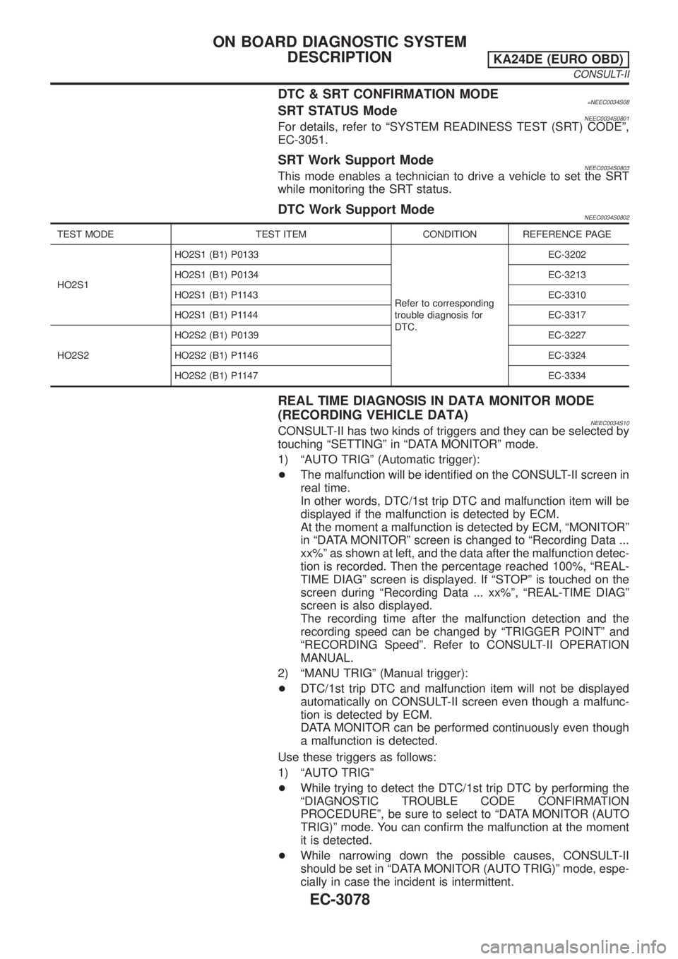
DTC & SRT CONFIRMATION MODE=NEEC0034S08SRT STATUS ModeNEEC0034S0801For details, refer to ªSYSTEM READINESS TEST (SRT) CODEº,
EC-3051.
SRT Work Support ModeNEEC0034S0803This mode enables a technician to drive a vehicle to set the SRT
while monitoring the SRT status.
DTC Work Support ModeNEEC0034S0802
TEST MODE TEST ITEM CONDITION REFERENCE PAGE
HO2S1HO2S1 (B1) P0133
Refer to corresponding
trouble diagnosis for
DTC.EC-3202
HO2S1 (B1) P0134 EC-3213
HO2S1 (B1) P1143 EC-3310
HO2S1 (B1) P1144 EC-3317
HO2S2HO2S2 (B1) P0139 EC-3227
HO2S2 (B1) P1146 EC-3324
HO2S2 (B1) P1147 EC-3334
REAL TIME DIAGNOSIS IN DATA MONITOR MODE
(RECORDING VEHICLE DATA)
NEEC0034S10CONSULT-II has two kinds of triggers and they can be selected by
touching ªSETTINGº in ªDATA MONITORº mode.
1) ªAUTO TRIGº (Automatic trigger):
+The malfunction will be identified on the CONSULT-II screen in
real time.
In other words, DTC/1st trip DTC and malfunction item will be
displayed if the malfunction is detected by ECM.
At the moment a malfunction is detected by ECM, ªMONITORº
in ªDATA MONITORº screen is changed to ªRecording Data ...
xx%º as shown at left, and the data after the malfunction detec-
tion is recorded. Then the percentage reached 100%, ªREAL-
TIME DIAGº screen is displayed. If ªSTOPº is touched on the
screen during ªRecording Data ... xx%º, ªREAL-TIME DIAGº
screen is also displayed.
The recording time after the malfunction detection and the
recording speed can be changed by ªTRIGGER POINTº and
ªRECORDING Speedº. Refer to CONSULT-II OPERATION
MANUAL.
2) ªMANU TRIGº (Manual trigger):
+DTC/1st trip DTC and malfunction item will not be displayed
automatically on CONSULT-II screen even though a malfunc-
tion is detected by ECM.
DATA MONITOR can be performed continuously even though
a malfunction is detected.
Use these triggers as follows:
1) ªAUTO TRIGº
+While trying to detect the DTC/1st trip DTC by performing the
ªDIAGNOSTIC TROUBLE CODE CONFIRMATION
PROCEDUREº, be sure to select to ªDATA MONITOR (AUTO
TRIG)º mode. You can confirm the malfunction at the moment
it is detected.
+While narrowing down the possible causes, CONSULT-II
should be set in ªDATA MONITOR (AUTO TRIG)º mode, espe-
cially in case the incident is intermittent.
ON BOARD DIAGNOSTIC SYSTEM
DESCRIPTION
KA24DE (EURO OBD)
CONSULT-II
EC-3078
Page 131 of 1306
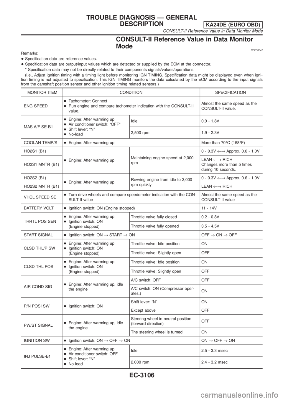
CONSULT-II Reference Value in Data Monitor
Mode
NEEC0042Remarks:
+Specification data are reference values.
+Specification data are output/input values which are detected or supplied by the ECM at the connector.
* Specification data may not be directly related to their components signals/values/operations.
(i.e., Adjust ignition timing with a timing light before monitoring IGN TIMING. Specification data might be displayed even when igni-
tion timing is not adjusted to specification. This IGN TIMING monitors the data calculated by the ECM according to the input signals
from the camshaft position sensor and other ignition timing related sensors.)
MONITOR ITEM CONDITION SPECIFICATION
ENG SPEED+Tachometer: Connect
+Run engine and compare tachometer indication with the CONSULT-II
value.Almost the same speed as the
CONSULT-II value.
MAS A/F SE-B1+Engine: After warming up
+Air conditioner switch: ªOFFº
+Shift lever: ªNº
+No-loadIdle 0.9 - 1.8V
2,500 rpm 1.9 - 2.3V
COOLAN TEMP/S+Engine: After warming up More than 70ÉC (158ÉF)
HO2S1 (B1)
+Engine: After warming upMaintaining engine speed at 2,000
rpm0 - 0.3V¨Approx. 0.6 - 1.0V
HO2S1 MNTR (B1)LEAN¨RICH
Changes more than 5 times
during 10 seconds.
HO2S2 (B1)
+Engine: After warming upRevving engine from idle to 3,000
rpm quickly0 - 0.3V¨Approx. 0.6 - 1.0V
HO2S2 MNTR (B1)LEAN¨RICH
VHCL SPEED SE+Turn drive wheels and compare speedometer indication with the CON-
SULT-II valueAlmost the same speed as the
CONSULT-II value
BATTERY VOLT+Ignition switch: ON (Engine stopped) 11 - 14V
THRTL POS SEN+Engine: After warming up
+Ignition switch: ON
(Engine stopped)Throttle valve fully closed 0.2 - 0.8V
Throttle valve fully opened 3.5 - 4.5V
START SIGNAL+Ignition switch: ON®START®ON OFF®ON®OFF
CLSD THL/P SW+Engine: After warming up
+Ignition switch: ON
(Engine stopped)Throttle valve: Idle position ON
Throttle valve: Slightly open OFF
CLSD THL POS+Engine: After warming up
+Ignition switch: ON
(Engine stopped)Throttle valve: Idle position ON
Throttle valve: Slightly open OFF
AIR COND SIG+Engine: After warming up, idle
the engineA/C switch: OFF OFF
A/C switch: ON (Compressor oper-
ates.)ON
P/N POSI SW+Ignition switch: ONShift lever: ªNº ON
Except above OFF
PW/ST SIGNAL+Engine: After warming up, idle
the engineSteering wheel in neutral position
(forward direction)OFF
The steering wheel is turned ON
IGNITION SW+Ignition switch: ON®OFF®ON ON®OFF®ON
INJ PULSE-B1+Engine: After warming up
+Air conditioner switch: OFF
+Shift lever: ªNº
+No-loadIdle 2.5 - 3.3 msec
2,000 rpm 2.4 - 3.2 msec
TROUBLE DIAGNOSIS Ð GENERAL
DESCRIPTION
KA24DE (EURO OBD)
CONSULT-II Reference Value in Data Monitor Mode
EC-3106