2001 NISSAN ALMERA TINO fuel pressure
[x] Cancel search: fuel pressurePage 1217 of 3051
On Board Diagnosis LogicNLEC1507With the Air/Fuel Mixture Ratio Self-Learning Control, the actual mixture ratio can be brought closely to the
theoretical mixture ratio based on the mixture ratio feedback signal from the heated oxygen sensor 1 (front).
The ECM calculates the necessary compensation to correct the offset between the actual and the theoretical
ratios.
In case the amount of the compensation value is extremely large (The actual mixture ratio is too lean.), the
ECM judges the condition as the fuel injection system malfunction and lights up the MIL (2 trip detection logic).
Sensor Input Signal to ECM ECM function Actuator
Heated oxygen sensor 1 (front)Density of oxygen in exhaust gas
(Mixture ratio feedback signal)Fuel injection & mixture
ratio controlInjectors
DTC No. Malfunction is detected when ... Check Items (Possible Cause)
P0171+Fuel injection system does not operate properly.
+The amount of mixture ratio compensation is too large.
(The mixture ratio is too lean.)+Intake air leaks
+Heated oxygen sensor 1 (front)
+Injectors
+Exhaust gas leaks
+Incorrect fuel pressure
+Lack of fuel
+Mass air flow sensor
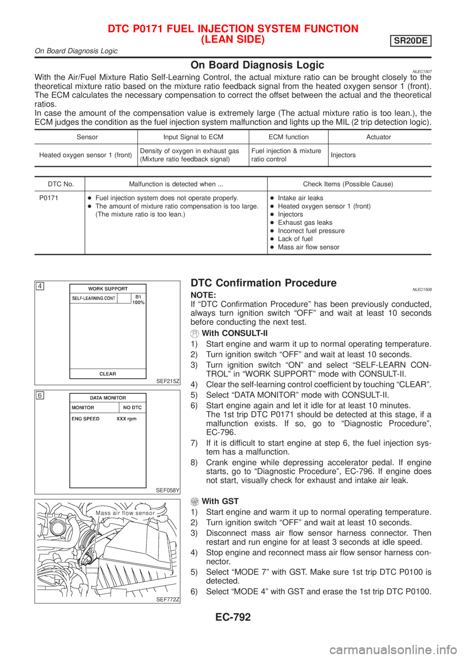
SEF215Z
SEF058Y
DTC Confirmation ProcedureNLEC1508NOTE:
If ªDTC Confirmation Procedureº has been previously conducted,
always turn ignition switch ªOFFº and wait at least 10 seconds
before conducting the next test.
With CONSULT-II
1) Start engine and warm it up to normal operating temperature.
2) Turn ignition switch ªOFFº and wait at least 10 seconds.
3) Turn ignition switch ªONº and select ªSELF-LEARN CON-
TROLº in ªWORK SUPPORTº mode with CONSULT-II.
4) Clear the self-learning control coefficient by touching ªCLEARº.
5) Select ªDATA MONITORº mode with CONSULT-II.
6) Start engine again and let it idle for at least 10 minutes.
The 1st trip DTC P0171 should be detected at this stage, if a
malfunction exists. If so, go to ªDiagnostic Procedureº,
EC-796.
7) If it is difficult to start engine at step 6, the fuel injection sys-
tem has a malfunction.
8) Crank engine while depressing accelerator pedal. If engine
starts, go to ªDiagnostic Procedureº, EC-796. If engine does
not start, visually check for exhaust and intake air leak.
SEF772Z
With GST
1) Start engine and warm it up to normal operating temperature.
2) Turn ignition switch ªOFFº and wait at least 10 seconds.
3) Disconnect mass air flow sensor harness connector. Then
restart and run engine for at least 3 seconds at idle speed.
4) Stop engine and reconnect mass air flow sensor harness con-
nector.
5) Select ªMODE 7º with GST. Make sure 1st trip DTC P0100 is
detected.
6) Select ªMODE 4º with GST and erase the 1st trip DTC P0100.
DTC P0171 FUEL INJECTION SYSTEM FUNCTION
(LEAN SIDE)
SR20DE
On Board Diagnosis Logic
EC-792
Page 1222 of 3051
4 CHECK FUEL PRESSURE
1. Release fuel pressure to zero.
Refer to EC-577.
2. Install fuel pressure gauge and check fuel pressure.
At idling:
When fuel pressure regulator valve vacuum hose is connected.
235 kPa (2.35 bar, 2.4 kg/cm
2, 34 psi)
When fuel pressure regulator valve vacuum hose is disconnected.
294 kPa (2.94 bar, 3.0 kg/cm
2, 43 psi)
OK or NG
OK©GO TO 6.
NG©GO TO 5.
5 DETECT MALFUNCTIONING PART
Check the following.
+Fuel pump and circuit (Refer to EC-1032.)
+Fuel pressure regulator (Refer to EC-578.)
+Fuel lines (Refer to ªENGINE MAINTENANCEº in MA section.)
+Fuel filter for clogging
©Repair or replace.
6 CHECK MASS AIR FLOW SENSOR
With CONSULT-II
Check ªMASS AIR FLOWº in ªDATA MONITORº mode with CONSULT-II.
at idling: 2.5 - 5.0 g´m/sec
at 2,500 rpm: 7.1 - 12.5 g´m/sec
With GST
Check mass air flow sensor signal in MODE 1 with GST.
at idling: 2.5 - 5.0 g´m/sec
at 2,500 rpm: 7.1 - 12.5 g´m/sec
OK or NG
OK©GO TO 7.
NG©Check connectors for rusted terminals or loose connections in the mass air flow sensor
circuit or engine grounds. Refer to EC-679.
DTC P0171 FUEL INJECTION SYSTEM FUNCTION
(LEAN SIDE)
SR20DE
Diagnostic Procedure (Cont'd)
EC-797
Page 1225 of 3051
On Board Diagnosis LogicNLEC1511With the Air/Fuel Mixture Ratio Self-Learning Control, the actual mixture ratio can be brought closely to the
theoretical mixture ratio based on the mixture ratio feedback signal from the heated oxygen sensor 1 (front).
The ECM calculates the necessary compensation to correct the offset between the actual and the theoretical
ratios.
In case the amount of the compensation value is extremely large (The actual mixture ratio is too rich.), the
ECM judges the condition as the fuel injection system malfunction and lights up the MI (2 trip detection logic).
Sensor Input Signal to ECM ECM function Actuator
Heated oxygen sensor 1 (front)Density of oxygen in exhaust gas
(Mixture ratio feedback signal)Fuel injection & mixture
ratio controlInjectors
DTC No. Malfunction is detected when ... Check Items (Possible Cause)
P0172+Fuel injection system does not operate properly.
+The amount of mixture ratio compensation is too large.
(The mixture ratio is too rich.)+Heated oxygen sensor 1 (front)
+Injectors
+Exhaust gas leaks
+Incorrect fuel pressure
+Mass air flow sensor
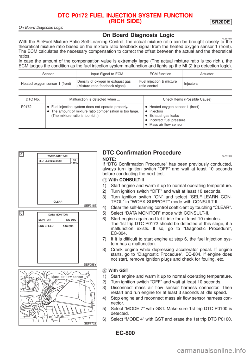
SEF215Z
SEF058Y
DTC Confirmation ProcedureNLEC1512NOTE:
If ªDTC Confirmation Procedureº has been previously conducted,
always turn ignition switch ªOFFº and wait at least 10 seconds
before conducting the next test.
With CONSULT-II
1) Start engine and warm it up to normal operating temperature.
2) Turn ignition switch ªOFFº and wait at least 10 seconds.
3) Turn ignition switch ªONº and select ªSELF-LEARN CON-
TROLº in ªWORK SUPPORTº mode with CONSULT-II.
4) Clear the self-learning control coefficient by touching ªCLEARº.
5) Select ªDATA MONITORº mode with CONSULT-II.
6) Start engine again and let it idle for at least 10 minutes.
The 1st trip DTC P0172 should be detected at this stage, if a
malfunction exists. If so, go to ªDiagnostic Procedureº,
EC-804.
7) If it is difficult to start engine at step 6, the fuel injection sys-
tem has a malfunction.
8) Crank engine while depressing accelerator pedal. If engine
starts, go to ªDiagnostic Procedureº, EC-804. If engine does
not start, remove ignition plugs and check for fouling, etc.
SEF772Z
With GST
1) Start engine and warm it up to normal operating temperature.
2) Turn ignition switch ªOFFº and wait at least 10 seconds.
3) Disconnect mass air flow sensor harness connector. Then
restart and run engine for at least 3 seconds at idle speed.
4) Stop engine and reconnect mass air flow sensor harness con-
nector.
5) Select ªMODE 7º with GST. Make sure 1st trip DTC P0100 is
detected.
6) Select ªMODE 4º with GST and erase the 1st trip DTC P0100.
DTC P0172 FUEL INJECTION SYSTEM FUNCTION
(RICH SIDE)
SR20DE
On Board Diagnosis Logic
EC-800
Page 1230 of 3051
3 CHECK FUEL PRESSURE
1. Release fuel pressure to zero.
Refer to EC-577.
2. Install fuel pressure gauge and check fuel pressure.
At idling:
When fuel pressure regulator valve vacuum hose is connected.
Approximately 235 kPa (2.35 bar, 2.4 kg/cm
2, 34 psi)
When fuel pressure regulator valve vacuum hose is disconnected.
Approximately 294 kPa (2.94 bar, 3.0 kg/cm
2, 43 psi)
OK or NG
OK©GO TO 5.
NG©GO TO 4.
4 DETECT MALFUNCTIONING PART
Check the following.
+Fuel pump and circuit (Refer to EC-1032.)
+Fuel pressure regulator (Refer to EC-578.)
©Repair or replace.
5 CHECK MASS AIR FLOW SENSOR
With CONSULT-II
Check ªMASS AIR FLOWº in ªDATA MONITORº mode with CONSULT-II.
at idling: 2.5 - 5.0 g´m/sec
at 2,500 rpm: 7.1 - 12.5 g´m/sec
With GST
Check mass air flow sensor signal in MODE 1 with GST.
at idling: 2.5 - 5.0 g´m/sec
at 2,500 rpm: 7.1 - 12.5 g´m/sec
OK or NG
OK©GO TO 6.
NG©Check connectors for rusted terminals or loose connections in the mass air flow sensor
circuit or engine grounds. Refer to EC-679.
DTC P0172 FUEL INJECTION SYSTEM FUNCTION
(RICH SIDE)
SR20DE
Diagnostic Procedure (Cont'd)
EC-805
Page 1233 of 3051
On Board Diagnosis LogicNLEC1752When a misfire occurs, engine speed will fluctuate (vary). If the engine speed fluctuates enough to cause the
CKP sensor to vary, ECM can detect a misfire.
Sensor Input Signal to ECM ECM function
Crankshaft position sensor (OBD) Engine speed On board diagnosis of misfire
The misfire detection logic consists of the following two conditions.
1. One Trip Detection Logic (Three Way Catalyst Damage)
On the first rip that a misfire condition occurs that can damage the three way catalyst (TWC) due to
overheating, the MI will blink.
When a misfire condition occurs, the ECM monitors the CKP sensor (OBD) signal every 200 engine revo-
lutions for a change.
When the misfire condition decreases to a level that will not damage the TWC, the MI will turn off.
If another misfire condition occurs that can damage the TWC on a second trip, the MI will blink.
When the misfire condition decreases to a level that will not damage the TWC, the MI will remain on.
If another misfire condition occurs that can damage the TWC, the MI will begin to blink again.
2. Two Trip Detection Logic (Exhaust quality deterioration)
For misfire conditions that will not cause damage to the TWC (but will affect vehicle emissions), the MI
will only light when the misfire is detected on a second trip. During this condition, the ECM monitors the
CKP sensor (OBD) signal every 1,000 engine revolutions.
A misfire malfunction can be detected on any one cylinder or on-multiple cylinders.
DTC No. Malfunction is detected when ... Check Items (Possible Cause)
P0300+Multiple cylinders misfire.+Improper spark plug
+Insufficient compression
+Incorrect fuel pressure
+EGR volume control valve
+The injector circuit is open or shorted
+Injectors
+Intake air leak
+The ignition secondary circuit is open or shorted
+Lack of fuel
+Drive plate
+Heated oxygen sensor 1 (front)
+Incorrect distributor roter P0301+No. 1 cylinder misfires.
P0302+No. 2 cylinder misfires.
P0303+No. 3 cylinder misfires.
P0304+No. 4 cylinder misfires.
SEF058Y
DTC Confirmation ProcedureNLEC1522CAUTION:
Always drive vehicle at a safe speed.
NOTE:
If ªDTC Confirmation Procedureº has been previously conducted,
always turn ignition switch ªOFFº and wait at least 10 seconds
before conducting the next test.
With CONSULT-II
1) Turn ignition switch ªONº, and select ªDATA MONITORº mode
with CONSULT-II.
2) Start engine and warm it up to normal operating temperature.
3) Turn ignition switch ªOFFº and wait at least 10 seconds.
4) Start engine again and drive at 1,500 - 3,000 rpm for at least
3 minutes.
Hold the accelerator pedal as steady as possible.
NOTE:
Refer to the freeze frame data for the test driving conditions.
5) If 1st trip DTC is detected, go to ªDiagnostic Procedureº,
EC-809.
With GST
Follow the procedure ªWith CONSULT-IIº above.
DTC P0300 - P0304 NO.4-1CYLINDER MISFIRE, MULTIPLE CYLINDER
MISFIRE
SR20DE
On Board Diagnosis Logic
EC-808
Page 1237 of 3051
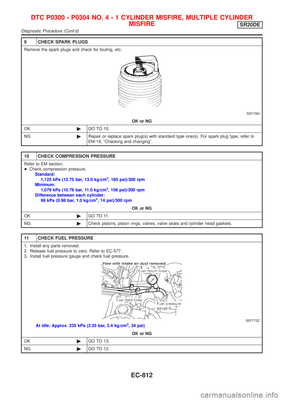
9 CHECK SPARK PLUGS
Remove the spark plugs and check for fouling, etc.
SEF156I
OK or NG
OK©GO TO 10.
NG©Repair or replace spark plug(s) with standard type one(s). For spark plug type, refer to
EM-19, ªChecking and changingº.
10 CHECK COMPRESSION PRESSURE
Refer to EM section.
+Check compression pressure.
Standard:
1,125 kPa (12.75 bar, 13.0 kg/cm
2, 185 psi)/300 rpm
Minimum:
1,079 kPa (10.79 bar, 11.0 kg/cm
2, 156 psi)/300 rpm
Difference between each cylinder:
98 kPa (0.98 bar, 1.0 kg/cm
2, 14 psi)/300 rpm
OK or NG
OK©GO TO 11.
NG©Check pistons, piston rings, valves, valve seats and cylinder head gaskets.
11 CHECK FUEL PRESSURE
1. Install any parts removed.
2. Release fuel pressure to zero. Refer to EC-577.
3. Install fuel pressure gauge and check fuel pressure.
SEF775Z
At idle: Approx. 235 kPa (2.35 bar, 2.4 kg/cm2, 34 psi)
OK or NG
OK©GO TO 13.
NG©GO TO 12.
DTC P0300 - P0304 NO.4-1CYLINDER MISFIRE, MULTIPLE CYLINDER
MISFIRE
SR20DE
Diagnostic Procedure (Cont'd)
EC-812
Page 1238 of 3051
12 DETECT MALFUNCTIONING PART
Check the following.
+Fuel pump and circuit (Refer to EC-1032.)
+Fuel pressure regulator (Refer to EC-578.)
+Fuel lines
+Fuel filter for clogging
©Repair or replace.
13 CHECK IGNITION TIMING
Perform ªBasic Inspectionº.
Refer to EC-623.
OK or NG
OK©GO TO 14.
NG©Adjust ignition timing.
14 CHECK HEATED OXYGEN SENSOR 1 (FRONT)
Refer to ªComponent Inspectionº, EC-715.
OK or NG
OK©GO TO 15.
NG©Replace heated oxygen sensor 1 (front).
15 CHECK MASS AIR FLOW SENSOR
With CONSULT-II
Check ªMASS AIR FLOWº in ªDATA MONITORº mode with CONSULT-II.
at idling: 2.5 - 5.0 g´m/sec
at 2,500 rpm: 7.1 - 12.5 g´m/sec
With GST
Check mass air flow sensor signal in MODE 1 with GST.
at idling: 2.5 - 5.0 g´m/sec
at 2,500 rpm: 7.1 - 12.5 g´m/sec
OK or NG
OK©GO TO 17.
NG©GO TO 16.
16 CHECK CONNECTORS
Check connectors for rusted terminals or loose connections in the mass air flow sensor circuit or engine grounds.
Refer to EC-679.
OK or NG
NG©Repair or replace it.
17 CHECK SYMPTOM MATRIX CHART
Check items on the rough idle symptom in ªSymptom Matrix Chartº, EC-648.
OK or NG
OK©GO TO 18.
NG©Repair or replace.
DTC P0300 - P0304 NO.4-1CYLINDER MISFIRE, MULTIPLE CYLINDER
MISFIRE
SR20DE
Diagnostic Procedure (Cont'd)
EC-813
Page 1461 of 3051
Diagnostic ProcedureNLEC1870
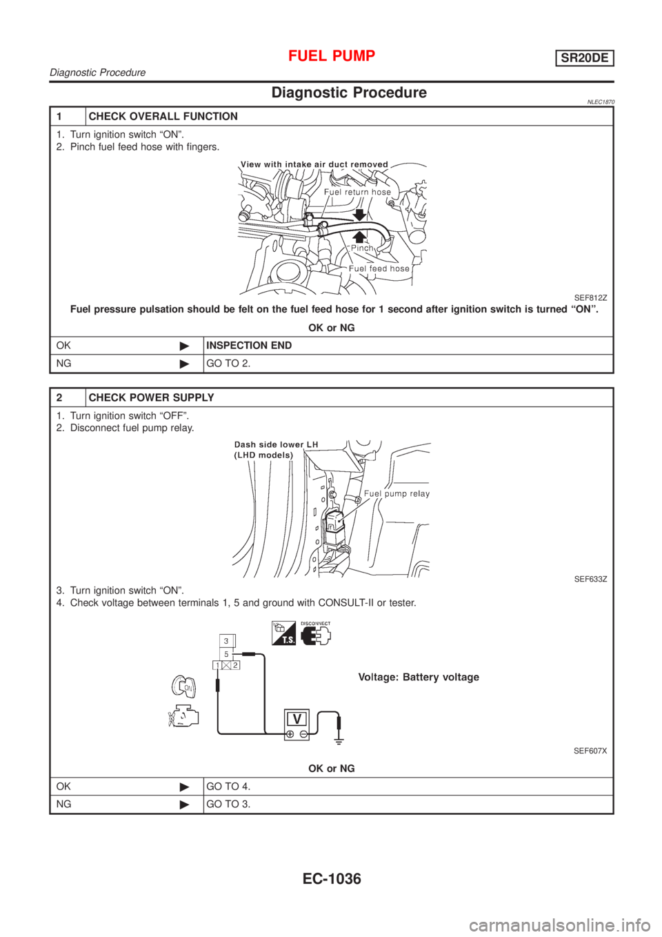
1 CHECK OVERALL FUNCTION
1. Turn ignition switch ªONº.
2. Pinch fuel feed hose with fingers.
SEF812Z
Fuel pressure pulsation should be felt on the fuel feed hose for 1 second after ignition switch is turned ªONº.
OK or NG
OK©INSPECTION END
NG©GO TO 2.
2 CHECK POWER SUPPLY
1. Turn ignition switch ªOFFº.
2. Disconnect fuel pump relay.
SEF633Z
3. Turn ignition switch ªONº.
4. Check voltage between terminals 1, 5 and ground with CONSULT-II or tester.
SEF607X
OK or NG
OK©GO TO 4.
NG©GO TO 3.
FUEL PUMPSR20DE
Diagnostic Procedure
EC-1036