2001 NISSAN ALMERA TINO fuel pressure
[x] Cancel search: fuel pressurePage 2589 of 3051

NEW TERMNEW ACRONYM /
ABBREVIATIONOLD TERM
Manifold absolute pressure MAP ***
Manifold absolute pressure/Barometric
pressure switch solenoid valveMAP/BARO switch solenoid valve ***
Manifold absolute pressure sensor MAPS ***
Manifold differential pressure MDP ***
Manifold differential pressure sensor MDPS ***
Manifold surface temperature MST ***
Manifold surface temperature sensor MSTS ***
Manifold vacuum zone MVZ ***
Manifold vacuum zone sensor MVZS ***
Mass air flow sensor MAFS Air flow meter
Mixture control solenoid valve MC solenoid valve Air-fuel ratio control solenoid valve
Multiport fuel injection system MFI system Fuel injection control
Neutral position switch *** Neutral switch
Nonvolatile random access memory NVRAM ***
On board diagnostic system OBD system Self-diagnoses
Open loop OL Open loop
Oxidation catalyst OC Catalyst
Oxidation catalytic converter system OC system ***
Oxygen sensor O2S Exhaust gas sensor
Park position switch *** Park switch
Park/neutral position switch PNP switch Park/neutral switch
Periodic trap oxidizer system PTOX system ***
Powertrain control module PCM ***
Programmable read only memory PROM ***
Pulsed secondary air injection control
solenoid valvePAIRC solenoid valve AIV control solenoid valve
Pulsed secondary air injection system PAIR system Air induction valve (AIV) control
Pulsed secondary air injection valve PAIR valve Air induction valve
Random access memory RAM ***
Read only memory ROM ***
Scan tool ST ***
Secondary air injection pump AIR pump ***
Secondary air injection system AIR system ***
Sequential multiport fuel injection system SFI system Sequential fuel injection
Service reminder indicator SRI ***
Simultaneous multiport fuel injection sys-
tem*** Simultaneous fuel injection
ISO 15031–2 TERMINOLOGY LIST
ISO 15031–2 Terminology List (Cont’d)
GI-50
Page 2698 of 3051

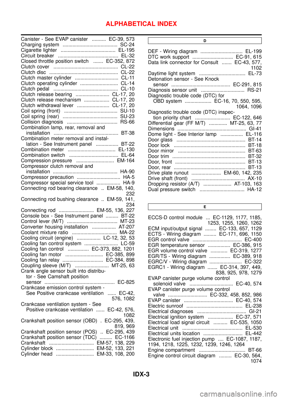
Canister - See EVAP canister .......... EC-39, 573
Charging system ....................................... SC-24
Cigarette lighter ....................................... EL-195
Circuit breaker ........................................... EL-32
Closed throttle position switch ....... EC-352, 872
Clutch cover .............................................. CL-22
Clutch disc ................................................. CL-22
Clutch master cylinder ............................... CL-11
Clutch operating cylinder ........................... CL-14
Clutch pedal .............................................. CL-10
Clutch release bearing ........................ CL-17, 20
Clutch release mechanism .................. CL-17, 20
Clutch withdrawal lever ....................... CL-17, 20
Coil spring (front) ...................................... SU-10
Coil spring (rear) ....................................... SU-23
Collision diagnosis .................................... RS-66
Combination lamp, rear, removal and
installation .............................................. BT-38
Combination meter removal and instal-
lation - See Instrument panel ................ BT-22
Combination meter .................................. EL-130
Combination switch ................................... EL-64
Compression pressure ........................... EM-164
Compressor clutch removal and
installation .............................................. HA-90
Compressor precaution ............................... HA-5
Compressor special service tool ................. HA-9
Connecting rod bearing clearance .. EM-58, 140,
232
Connecting rod bushing clearance .. EM-59, 141,
234
Connecting rod ......................... EM-55, 136, 227
Console box - See Instrument panel ......... BT-22
Control lever (M/T) .................................... MT-23
Converter housing installation ................. AT-207
Coolant mixture ratio ................................ MA-22
Cooling circuit (engine) ................. LC-12, 32, 53
Cooling fan control system ........................ LC-59
Cooling fan control ............... EC-373, 882, 1201
Cooling fan motor ........................... EC-385, 899
Cooling fan relay ............................. EC-384, 898
Coupling sleeve (M/T) ........................ MT-25, 63
Crank angle sensor built into distribu-
tor - See Camshaft position
sensor .................................................. EC-825
Crankcase emission control system -
See Positive crankcase ventilation ...... EC-42,
576, 1082
Crankcase ventilation system - See
Positive crankcase ventilation ...... EC-42, 576,
1082
Crankshaft position sensor (OBD) . EC-295, 439,
819, 969
Crankshaft position sensor (POS) .. EC-295, 439
Crankshaft position sensor (TDC) ......... EC-1166
Crankshaft ................................ EM-57, 138, 229
Cylinder block ........................... EM-52, 133, 221
Cylinder head ........................... EM-33, 108, 200D
DEF - Wiring diagram .............................. EL-199
DTC work support ............................. EC-91, 615
Data link connector for Consult ....... EC-43, 577,
1102
Daytime light system ................................. EL-73
Detonation sensor - See Knock
sensor .......................................... EC-291, 815
Diagnosis sensor unit ............................... RS-21
Diagnostic trouble code (DTC) for
OBD system ................... EC-16, 70, 550, 595,
1064, 1096
Diagnostic trouble code (DTC) inspec-
tion priority chart ......................... EC-122, 646
Differential gear (FF M/T) ............. MT-25, 63, 77
Dimensions ................................................. GI-41
Dome light - See Interior lamp ................ EL-116
Door glass ................................................. BT-14
Door lock ................................................... BT-18
Door mirror ................................................ BT-63
Door trim .................................................... BT-32
Door, front .................................................. BT-13
Door, rear ................................................... BT-13
Drive plate runout ..................... EM-60, 142, 235
Drive shaft (front) ...................................... AX-10
Dropping resistor (A/T) .................... AT-103, 163
Dual pressure switch ................................ HA-12
E
ECCS-D control module ... EC-1129, 1177, 1185,
1253, 1255, 1260, 1262
ECM input/output signal ........ EC-133, 657, 1129
ECTS - Wiring diagram ......... EC-171, 696, 1150
EGR control valve ................................... EC-400
EGR temperature sensor ................ EC-386, 915
EGR volume control valve ............ EC-319, 1277
EGR/TS - Wiring diagram ............... EC-389, 918
EGRC/V - Wiring diagram ....................... EC-322
EGRC1 - Wiring diagram ....... EC-314, 397, 449,
838, 925, 978, 1279
EVAP canister purge volume control
solenoid valve ............................... EC-40, 574
EVAP canister purge volume control
valve ............................ EC-332, 458, 852, 986
EVAP canister ................................... EC-40, 574
Electric sunroof ........................................ EL-238
Electrical diagnoses ................................... GI-21
Electrical ignition system .................. EC-37, 571
Electrical load signal circuit .......... EC-535, 1050
Electrical unit ........................................... EL-530
Electrical units location ............................ EL-442
Electronic fuel injection pump .... EC-1087, 1187,
1194, 1218, 1225, 1232, 1239, 1246, 1264
Engine compartment ................................. BT-66
Engine control circuit diagram ......... EC-30, 564,
1074
ALPHABETICAL INDEX
IDX-3
Page 2699 of 3051

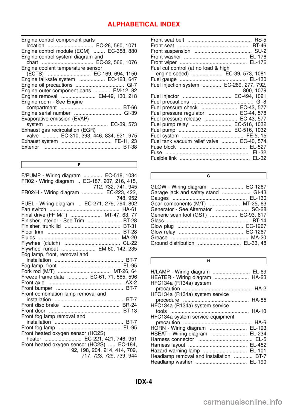
Engine control component parts
location ................................ EC-26, 560, 1071
Engine control module (ECM) ........ EC-358, 880
Engine control system diagram and
chart .................................... EC-32, 566, 1076
Engine coolant temperature sensor
(ECTS) .............................. EC-169, 694, 1150
Engine fail-safe system .................. EC-123, 647
Engine oil precautions .................................. GI-7
Engine outer component parts ........... EM-12, 82
Engine removal ........................ EM-49, 130, 218
Engine room - See Engine
compartment .......................................... BT-66
Engine serial number ................................. GI-39
Evaporative emission (EVAP)
system ........................................... EC-39, 573
Exhaust gas recirculation (EGR)
valve ........... EC-310, 393, 446, 834, 921, 975
Exhaust system ................................... FE-11, 23
Exterior ...................................................... BT-38
F
F/PUMP - Wiring diagram ............. EC-518, 1034
FR02 - Wiring diagram .. EC-187, 207, 216, 415,
712, 732, 741, 945
FR02/H - Wiring diagram ............... EC-223, 422,
748, 952
FUEL - Wiring diagram ... EC-271, 279, 794, 802
Fan switch ................................................. HA-61
Final drive (FF M/T) ...................... MT-47, 63, 77
Finisher, interior - See Trim ....................... BT-28
Finisher, trunk lid ....................................... BT-31
Floor trim ................................................... BT-28
Fluids ........................................................ MA-20
Flywheel (clutch) ....................................... CL-22
Flywheel runout ........................ EM-60, 142, 235
Fog lamp, front, removal and
installation ................................................ BT-7
Fog lamp, front .......................................... EL-95
Fork rod (M/T) ..................................... MT-26, 64
Freeze frame data .............. EC-61, 71, 585, 596
Front axle .................................................... AX-2
Front bumper ............................................... BT-7
Front combination lamp removal and
installation ................................................ BT-7
Front disc brake ........................................ BR-24
Front door .................................................. BT-13
Front fog lamp removal and
installation ................................................ BT-7
Front fog lamp ........................................... EL-95
Front heated oxygen sensor (HO2S)
heater .......................... EC-221, 421, 746, 951
Front heated oxygen sensor (HO2S) ..... EC-184,
192, 198, 204, 214, 414, 709,
717, 723, 729, 739, 944Front seat belt ............................................. RS-5
Front seat .................................................. BT-46
Front suspension ........................................ SU-2
Front washer ............................................ EL-176
Front wiper ............................................... EL-176
Fuel cut control (at no load & high
engine speed) ..................... EC-39, 573, 1081
Fuel gauge ............................................... EL-130
Fuel injection system ............. EC-269, 277, 792,
800, 1079
Fuel injector .................................. EC-494, 1021
Fuel precautions ........................................... GI-8
Fuel pressure check ......................... EC-43, 577
Fuel pressure regulator .................... EC-44, 578
Fuel pressure release ....................... EC-43, 577
Fuel pump relay ............................ EC-516, 1032
Fuel pump ..................................... EC-516, 1032
Fuel system ........................................... FE-5, 15
Fuel tank vacuum relief valve ........... EC-40, 574
Fuse block ............................................... EL-527
Fuse ........................................................... EL-32
Fusible link ................................................. EL-32G
GLOW - Wiring diagram ....................... EC-1267
Garage jack and safety stand .................... GI-43
Gauges .................................................... EL-130
Gear components (M/T) ..................... MT-25, 63
Generator - See Alternator ....................... SC-28
Generic scan tool (GST) ................... EC-93, 617
Glass .......................................................... BT-14
Glow plug .............................................. EC-1267
Glow relay ............................................. EC-1267
Grease ...................................................... MA-20
Ground distribution .............................. EL-33, 48
H
H/LAMP - Wiring diagram .......................... EL-69
HEATER - Wiring diagram ........................ HA-23
HFC134a (R134a) system
precaution ................................................ HA-2
HFC134a (R134a) system service
procedure .............................................. HA-85
HFC134a (R134a) system service
tools ....................................................... HA-10
HFC134a system service equipment
precaution ................................................ HA-6
HORN - Wiring diagram .......................... EL-193
HSEAT - Wiring diagram ......................... EL-234
Harness connector ...................................... EL-5
Harness layout ......................................... EL-452
Hazard warning lamp .............................. EL-101
Headlamp removal and installation ............. BT-7
Headlamp washer .................................... EL-190
ALPHABETICAL INDEX
IDX-4
Page 2700 of 3051

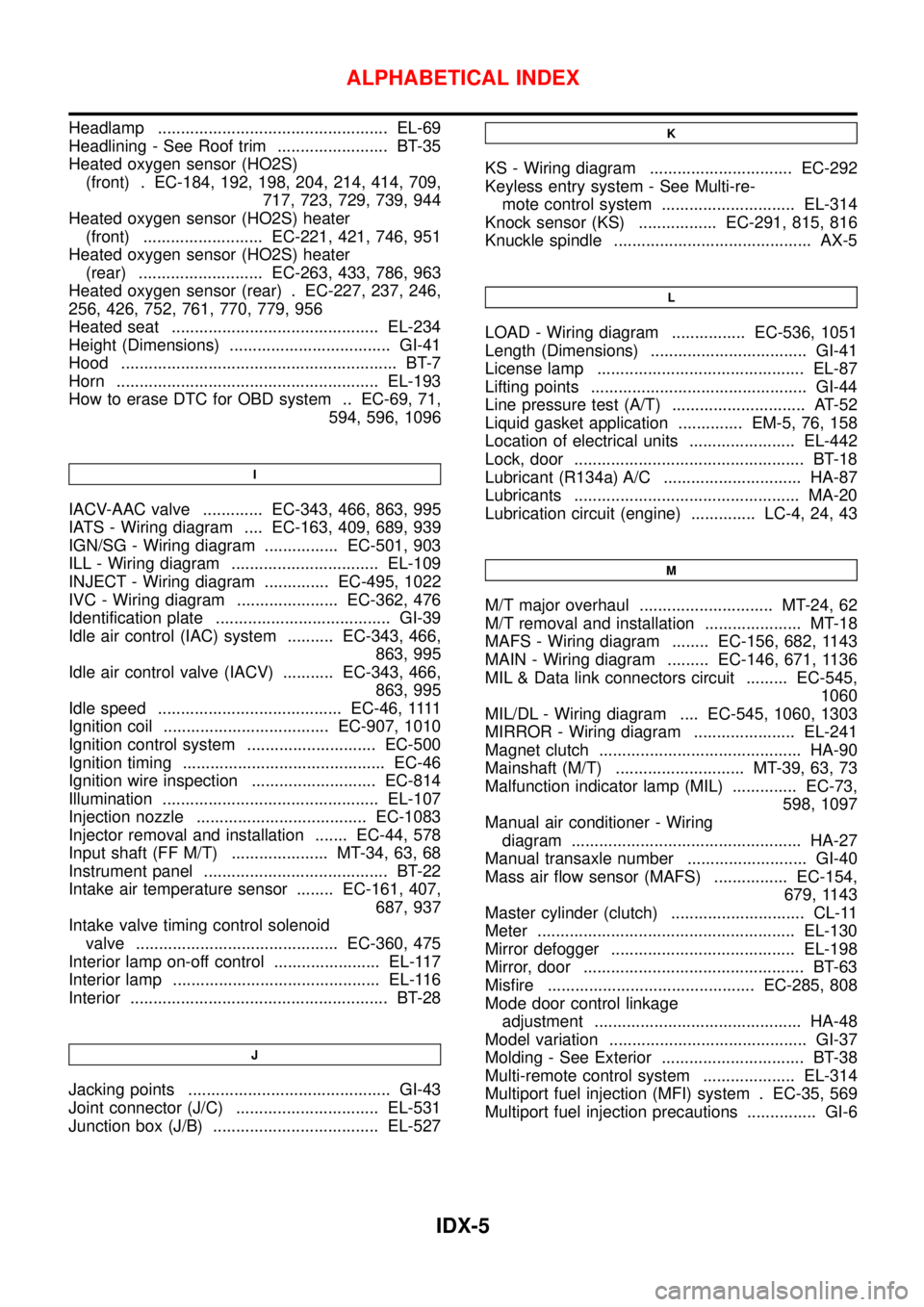
Headlamp .................................................. EL-69
Headlining - See Roof trim ........................ BT-35
Heated oxygen sensor (HO2S)
(front) . EC-184, 192, 198, 204, 214, 414, 709,
717, 723, 729, 739, 944
Heated oxygen sensor (HO2S) heater
(front) .......................... EC-221, 421, 746, 951
Heated oxygen sensor (HO2S) heater
(rear) ........................... EC-263, 433, 786, 963
Heated oxygen sensor (rear) . EC-227, 237, 246,
256, 426, 752, 761, 770, 779, 956
Heated seat ............................................. EL-234
Height (Dimensions) ................................... GI-41
Hood ............................................................ BT-7
Horn ......................................................... EL-193
How to erase DTC for OBD system .. EC-69, 71,
594, 596, 1096
I
IACV-AAC valve ............. EC-343, 466, 863, 995
IATS - Wiring diagram .... EC-163, 409, 689, 939
IGN/SG - Wiring diagram ................ EC-501, 903
ILL - Wiring diagram ................................ EL-109
INJECT - Wiring diagram .............. EC-495, 1022
IVC - Wiring diagram ...................... EC-362, 476
Identification plate ...................................... GI-39
Idle air control (IAC) system .......... EC-343, 466,
863, 995
Idle air control valve (IACV) ........... EC-343, 466,
863, 995
Idle speed ........................................ EC-46,1111
Ignition coil .................................... EC-907, 1010
Ignition control system ............................ EC-500
Ignition timing ............................................ EC-46
Ignition wire inspection ........................... EC-814
Illumination ............................................... EL-107
Injection nozzle ..................................... EC-1083
Injector removal and installation ....... EC-44, 578
Input shaft (FF M/T) ..................... MT-34, 63, 68
Instrument panel ........................................ BT-22
Intake air temperature sensor ........ EC-161, 407,
687, 937
Intake valve timing control solenoid
valve ............................................ EC-360, 475
Interior lamp on-off control ....................... EL-117
Interior lamp ............................................. EL-116
Interior ........................................................ BT-28
J
Jacking points ............................................ GI-43
Joint connector (J/C) ............................... EL-531
Junction box (J/B) .................................... EL-527
K
KS - Wiring diagram ............................... EC-292
Keyless entry system - See Multi-re-
mote control system ............................. EL-314
Knock sensor (KS) ................. EC-291, 815, 816
Knuckle spindle ........................................... AX-5
L
LOAD - Wiring diagram ................ EC-536, 1051
Length (Dimensions) .................................. GI-41
License lamp ............................................. EL-87
Lifting points ............................................... GI-44
Line pressure test (A/T) ............................. AT-52
Liquid gasket application .............. EM-5, 76, 158
Location of electrical units ....................... EL-442
Lock, door .................................................. BT-18
Lubricant (R134a) A/C .............................. HA-87
Lubricants ................................................. MA-20
Lubrication circuit (engine) .............. LC-4, 24, 43
M
M/T major overhaul ............................. MT-24, 62
M/T removal and installation ..................... MT-18
MAFS - Wiring diagram ........ EC-156, 682, 1143
MAIN - Wiring diagram ......... EC-146, 671, 1136
MIL & Data link connectors circuit ......... EC-545,
1060
MIL/DL - Wiring diagram .... EC-545, 1060, 1303
MIRROR - Wiring diagram ...................... EL-241
Magnet clutch ............................................ HA-90
Mainshaft (M/T) ............................ MT-39, 63, 73
Malfunction indicator lamp (MIL) .............. EC-73,
598, 1097
Manual air conditioner - Wiring
diagram .................................................. HA-27
Manual transaxle number .......................... GI-40
Mass air flow sensor (MAFS) ................ EC-154,
679, 1143
Master cylinder (clutch) ............................. CL-11
Meter ........................................................ EL-130
Mirror defogger ........................................ EL-198
Mirror, door ................................................ BT-63
Misfire ............................................. EC-285, 808
Mode door control linkage
adjustment ............................................. HA-48
Model variation ........................................... GI-37
Molding - See Exterior ............................... BT-38
Multi-remote control system .................... EL-314
Multiport fuel injection (MFI) system . EC-35, 569
Multiport fuel injection precautions ............... GI-6
ALPHABETICAL INDEX
IDX-5
Page 2769 of 3051

NLMA0036
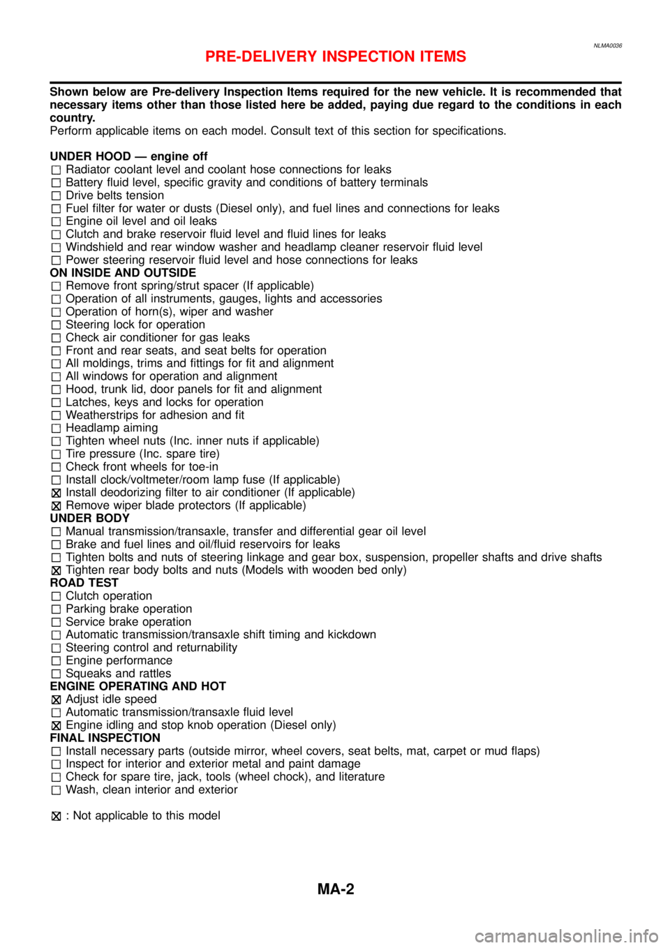
Shown below are Pre-delivery Inspection Items required for the new vehicle. It is recommended that
necessary items other than those listed here be added, paying due regard to the conditions in each
country.
Perform applicable items on each model. Consult text of this section for specifications.
UNDER HOOD — engine off
Radiator coolant level and coolant hose connections for leaks
Battery fluid level, specific gravity and conditions of battery terminals
Drive belts tension
Fuel filter for water or dusts (Diesel only), and fuel lines and connections for leaks
Engine oil level and oil leaks
Clutch and brake reservoir fluid level and fluid lines for leaks
Windshield and rear window washer and headlamp cleaner reservoir fluid level
Power steering reservoir fluid level and hose connections for leaks
ON INSIDE AND OUTSIDE
Remove front spring/strut spacer (If applicable)
Operation of all instruments, gauges, lights and accessories
Operation of horn(s), wiper and washer
Steering lock for operation
Check air conditioner for gas leaks
Front and rear seats, and seat belts for operation
All moldings, trims and fittings for fit and alignment
All windows for operation and alignment
Hood, trunk lid, door panels for fit and alignment
Latches, keys and locks for operation
Weatherstrips for adhesion and fit
Headlamp aiming
Tighten wheel nuts (Inc. inner nuts if applicable)
Tire pressure (Inc. spare tire)
Check front wheels for toe-in
Install clock/voltmeter/room lamp fuse (If applicable)
Install deodorizing filter to air conditioner (If applicable)
Remove wiper blade protectors (If applicable)
UNDER BODY
Manual transmission/transaxle, transfer and differential gear oil level
Brake and fuel lines and oil/fluid reservoirs for leaks
Tighten bolts and nuts of steering linkage and gear box, suspension, propeller shafts and drive shafts
Tighten rear body bolts and nuts (Models with wooden bed only)
ROAD TEST
Clutch operation
Parking brake operation
Service brake operation
Automatic transmission/transaxle shift timing and kickdown
Steering control and returnability
Engine performance
Squeaks and rattles
ENGINE OPERATING AND HOT
Adjust idle speed
Automatic transmission/transaxle fluid level
Engine idling and stop knob operation (Diesel only)
FINAL INSPECTION
Install necessary parts (outside mirror, wheel covers, seat belts, mat, carpet or mud flaps)
Inspect for interior and exterior metal and paint damage
Check for spare tire, jack, tools (wheel chock), and literature
Wash, clean interior and exterior
: Not applicable to this model
PRE-DELIVERY INSPECTION ITEMS
MA-2
Page 2770 of 3051

NLMA0004
General maintenance includes those items which should be checked during the normal day-to-day operation
of the vehicle. They are essential if the vehicle is to continue operating properly. The owners can perform the
checks and inspections themselves or they can have their NISSAN dealers do them for a nominal charge.
OUTSIDE THE VEHICLE
The maintenance items listed here should be performed from time to time, unless otherwise specified.
Item Reference page
TiresCheck the pressure with a gauge periodically when at a service station,
including the spare, and adjust to the specified pressure if necessary. Check
carefully for damage, cuts or excessive wear.—
Windshield wiper
bladesCheck for cracks or wear if not functioning correctly. —
Doors and engine
hoodCheck that all doors, the engine hood, the trunk lid and back door operate
properly. Also ensure that all latches lock securely. Lubricate if necessary.
Make sure that the secondary latch keeps the hood from opening when the
primary latch is released.
When driving in areas using road salt or other corrosive materials, check for
lubrication frequently.BT-7
BT-13
Tire rotationTires should be rotated every 10,000 km (6,000 miles). SU-8
INSIDE THE VEHICLE
The maintenance items listed here should be checked on a regular basis, such as when performing periodic maintenance, cleaning the
vehicle, etc.
Item Reference page
LampsMake sure that the headlamps, stop lamps, tail lamps, turn signal lamps,
and other lamps are all operating properly and installed securely. Also check
headlamp aim.—
Warning lamps and
chimesMake sure that all warning lamps and buzzers/chimes are operating prop-
erly.—
Steering wheelCheck that it has the specified play.
Check for changes in the steering conditions, such as excessive free play,
hard steering or strange noises.
Free play: Less than 35 mm (1.38 in)—
Seat beltsCheck that all parts of the seat belt system (e.g. buckles, anchors, adjusters
and retractors) operate properly and smoothly, and are installed securely.
Check the belt webbing for cuts, fraying, wear or damage.RS-3
UNDER THE HOOD AND VEHICLE
The maintenance items listed here should be checked periodically e.g. each time you check the engine oil or refuel.
Item Reference page
Windshield washer
fluidCheck that there is adequate fluid in the tank. —
Engine coolant levelCheck the coolant level when the engine is cold. LC-19, LC-59
Engine oil levelCheck the level after parking the vehicle (on level ground) and turning off
the engine.LC-8, LC-28
Brake and clutch
fluid levelsMake sure that the brake and clutch fluid levels are between the “MAX” and
“MIN” lines on the reservoir.BR-7
BatteryCheck the fluid level in each cell. It should be between the “MAX” and “MIN”
lines.—
GENERAL MAINTENANCE
MA-3