2001 NISSAN ALMERA TINO fuel pressure
[x] Cancel search: fuel pressurePage 1074 of 3051
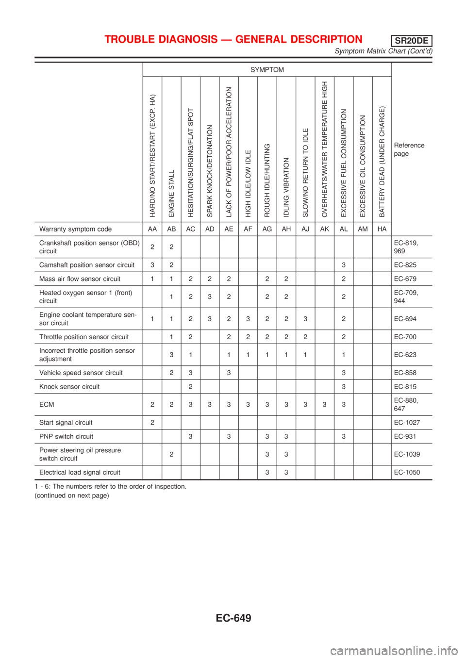
SYMPTOM
Reference
page
HARD/NO START/RESTART (EXCP. HA)
ENGINE STALL
HESITATION/SURGING/FLAT SPOT
SPARK KNOCK/DETONATION
LACK OF POWER/POOR ACCELERATION
HIGH IDLE/LOW IDLE
ROUGH IDLE/HUNTING
IDLING VIBRATION
SLOW/NO RETURN TO IDLE
OVERHEATS/WATER TEMPERATURE HIGH
EXCESSIVE FUEL CONSUMPTION
EXCESSIVE OIL CONSUMPTION
BATTERY DEAD (UNDER CHARGE)
Warranty symptom code AA AB AC AD AE AF AG AH AJ AK AL AM HA
Crankshaft position sensor (OBD)
circuit22EC-819,
969
Camshaft position sensor circuit 3 2 3 EC-825
Mass air flow sensor circuit11222 22 2EC-679
Heated oxygen sensor 1 (front)
circuit1232 22 2EC-709,
944
Engine coolant temperature sen-
sor circuit112323223 2EC-694
Throttle position sensor circuit 1 222222 2EC-700
Incorrect throttle position sensor
adjustment31 11111 1EC-623
Vehicle speed sensor circuit 2 3 3 3 EC-858
Knock sensor circuit 2 3 EC-815
ECM 22333333333EC-880,
647
Start signal circuit 2EC-1027
PNP switch circuit 3 3 3 3 3 EC-931
Power steering oil pressure
switch circuit2 3 3 EC-1039
Electrical load signal circuit 3 3 EC-1050
1 - 6: The numbers refer to the order of inspection.
(continued on next page)
TROUBLE DIAGNOSIS Ð GENERAL DESCRIPTIONSR20DE
Symptom Matrix Chart (Cont'd)
EC-649
Page 1091 of 3051
DescriptionNLEC1748The specification (SP) value indicates the tolerance of the value that is displayed in ªDATA MONITOR (SPEC)º
mode of CONSULT-II during normal operation of the Engine Control System. When the value in ªDATA MONI-
TOR (SPEC)º mode is within the SP value, the Engine Control System is confirmed OK. When the value in
ªDATA MONITOR (SPEC)º mode is NOT within the SP value, the Engine Control System may have one or
more malfunctions.
The SP value is used to detect malfunctions that may affect the Engine Control System, but will not light the
MIL.
The SP value will be displayed for the following three items:
+B/FUEL SCHDL (The fuel injection pulse width programmed into ECM prior to any learned on board cor-
rection)
+A/F ALPHA-B1/B2 (The mean value of air-fuel ratio feedback correction factor per cycle)
+MAS A/F SE-B1 (The signal voltage of the mass air flow sensor)
Testing ConditionNLEC1749+Vehicle driven distance: More than 5,000 km (3,107 miles)
+Barometric pressure: 98.3 - 104.3 kPa (0.983 - 1.043 bar, 1.003 - 1.064 kg/cm2, 14.25 - 15.12 psi)
+Atmospheric temperature: 20 - 30ÉC (68 - 86ÉF)
+Engine coolant temperature: 75 - 95ÉC (167 - 203ÉF)
+Transmission: Warmed-up*1
+Electrical load: Not applied*2
+Engine speed: Idle
*1: For after the engine is warmed up to normal operating temperature, drive vehicle until ªFLUID TEMP SEº
(CVT fluid temperature sensor signal) indicates less than 0.9V.
*2: Rear window defogger switch, air conditioner switch, lighting switch are ªOFFº. Cooling fans are not oper-
ating. Steering wheel is straight ahead.
SEF601Z
Inspection ProcedureNLEC1750NOTE:
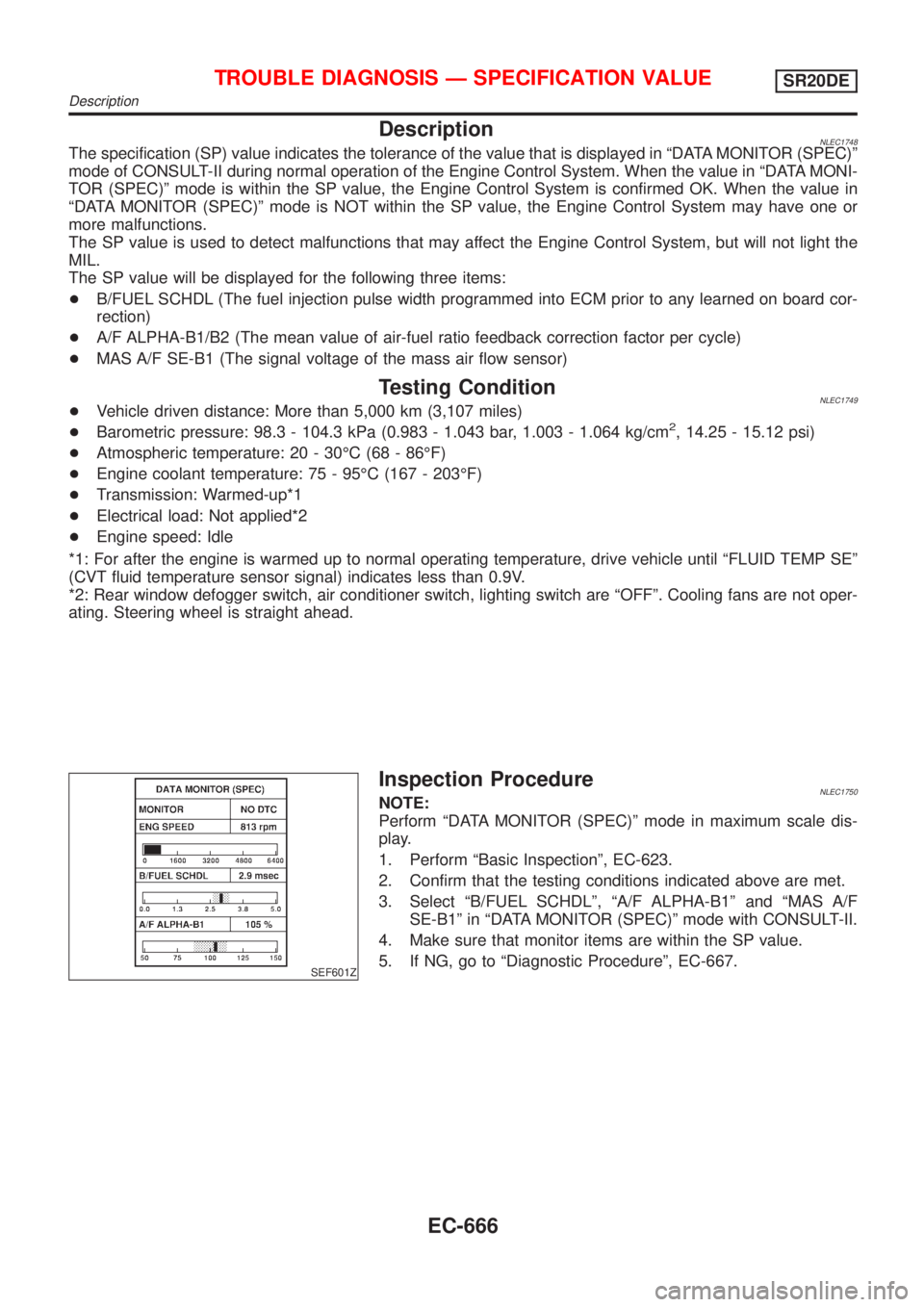
Perform ªDATA MONITOR (SPEC)º mode in maximum scale dis-
play.
1. Perform ªBasic Inspectionº, EC-623.
2. Confirm that the testing conditions indicated above are met.
3. Select ªB/FUEL SCHDLº, ªA/F ALPHA-B1º and ªMAS A/F
SE-B1º in ªDATA MONITOR (SPEC)º mode with CONSULT-II.
4. Make sure that monitor items are within the SP value.
5. If NG, go to ªDiagnostic Procedureº, EC-667.
TROUBLE DIAGNOSIS Ð SPECIFICATION VALUESR20DE
Description
EC-666
Page 1143 of 3051
SEF300U
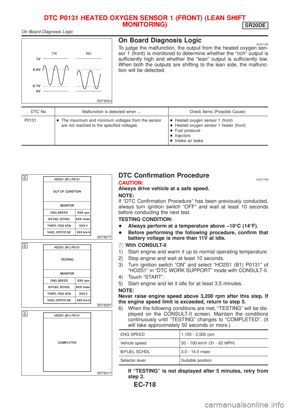
On Board Diagnosis LogicNLEC1425To judge the malfunction, the output from the heated oxygen sen-
sor 1 (front) is monitored to determine whether the ªrichº output is
sufficiently high and whether the ªleanº output is sufficiently low.
When both the outputs are shifting to the lean side, the malfunc-
tion will be detected.
DTC No. Malfunction is detected when ... Check Items (Possible Cause)
P0131+The maximum and minimum voltages from the sensor
are not reached to the specified voltages.+Heated oxygen sensor 1 (front)
+Heated oxygen sensor 1 heater (front)
+Fuel pressure
+Injectors
+Intake air leaks
SEF827Y
SEF828Y
SEF651Y
DTC Confirmation ProcedureNLEC1426CAUTION:
Always drive vehicle at a safe speed.
NOTE:
If ªDTC Confirmation Procedureº has been previously conducted,
always turn ignition switch ªOFFº and wait at least 10 seconds
before conducting the next test.
TESTING CONDITION:
+Always perform at a temperature above þ10ÉC (14ÉF).
+Before performing the following procedure, confirm that
battery voltage is more than 11V at idle.
With CONSULT-II
1) Start engine and warm it up to normal operating temperature.
2) Stop engine and wait at least 10 seconds.
3) Turn ignition switch ªONº and select ªHO2S1 (B1) P0131º of
ªHO2S1º in ªDTC WORK SUPPORTº mode with CONSULT-II.
4) Touch ªSTARTº.
5) Start engine and let it idle for at least 3.5 minutes.
NOTE:
Never raise engine speed above 3,200 rpm after this step. If
the engine speed limit is exceeded, return to step 5.
6) When the following conditions are met, ªTESTINGº will be dis-
played on the CONSULT-II screen. Maintain the conditions
continuously until ªTESTINGº changes to ªCOMPLETEDº. (It
will take approximately 50 seconds or more.)
ENG SPEED 1,150 - 2,500 rpm
Vehicle speed 50 - 100 km/h (31 - 62 MPH)
B/FUEL SCHDL 3.0 - 14.0 msec
Selector lever Suitable position
If ªTESTINGº is not displayed after 5 minutes, retry from
step 2.
DTC P0131 HEATED OXYGEN SENSOR 1 (FRONT) (LEAN SHIFT
MONITORING)
SR20DE
On Board Diagnosis Logic
EC-718
Page 1149 of 3051
SEF299U
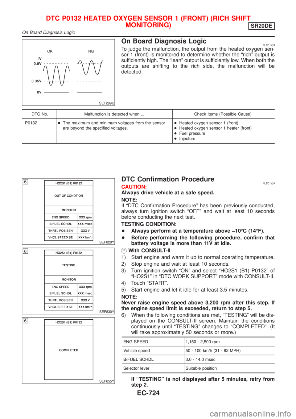
On Board Diagnosis LogicNLEC1433To judge the malfunction, the output from the heated oxygen sen-
sor 1 (front) is monitored to determine whether the ªrichº output is
sufficiently high. The ªleanº output is sufficiently low. When both the
outputs are shifting to the rich side, the malfunction will be
detected.
DTC No. Malfunction is detected when ... Check Items (Possible Cause)
P0132+The maximum and minimum voltages from the sensor
are beyond the specified voltages.+Heated oxygen sensor 1 (front)
+Heated oxygen sensor 1 heater (front)
+Fuel pressure
+Injectors
SEF829Y
SEF830Y
SEF655Y
DTC Confirmation ProcedureNLEC1434CAUTION:
Always drive vehicle at a safe speed.
NOTE:
If ªDTC Confirmation Procedureº has been previously conducted,
always turn ignition switch ªOFFº and wait at least 10 seconds
before conducting the next test.
TESTING CONDITION:
+Always perform at a temperature above þ10ÉC (14ÉF).
+Before performing the following procedure, confirm that
battery voltage is more than 11V at idle.
With CONSULT-II
1) Start engine and warm it up to normal operating temperature.
2) Stop engine and wait at least 10 seconds.
3) Turn ignition switch ªONº and select ªHO2S1 (B1) P0132º of
ªHO2S1º in ªDTC WORK SUPPORTº mode with CONSULT-II.
4) Touch ªSTARTº.
5) Start engine and let it idle for at least 3.5 minutes.
NOTE:
Never raise engine speed above 3,200 rpm after this step. If
the engine speed limit is exceeded, return to step 5.
6) When the following conditions are met, ªTESTINGº will be dis-
played on the CONSULT-II screen. Maintain the conditions
continuously until ªTESTINGº changes to ªCOMPLETEDº. (It
will take approximately 50 seconds or more.)
ENG SPEED 1,150 - 2,500 rpm
Vehicle speed 50 - 100 km/h (31 - 62 MPH)
B/FUEL SCHDL 3.0 - 14.0 msec
Selector lever Suitable position
If ªTESTINGº is not displayed after 5 minutes, retry from
step 2.
DTC P0132 HEATED OXYGEN SENSOR 1 (FRONT) (RICH SHIFT
MONITORING)
SR20DE
On Board Diagnosis Logic
EC-724
Page 1155 of 3051
SEF010V
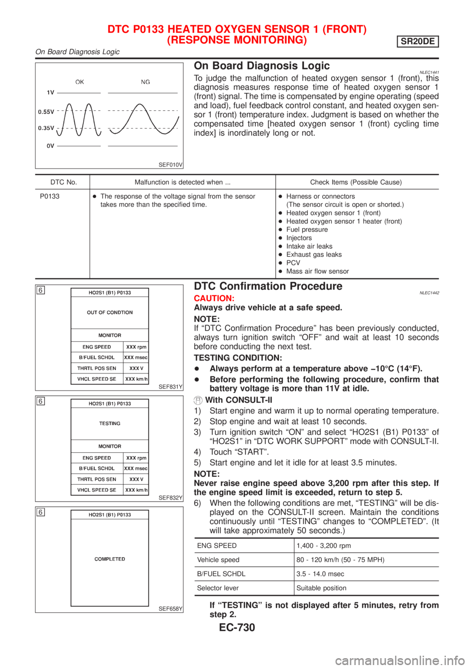
On Board Diagnosis LogicNLEC1441To judge the malfunction of heated oxygen sensor 1 (front), this
diagnosis measures response time of heated oxygen sensor 1
(front) signal. The time is compensated by engine operating (speed
and load), fuel feedback control constant, and heated oxygen sen-
sor 1 (front) temperature index. Judgment is based on whether the
compensated time [heated oxygen sensor 1 (front) cycling time
index] is inordinately long or not.
DTC No. Malfunction is detected when ... Check Items (Possible Cause)
P0133+The response of the voltage signal from the sensor
takes more than the specified time.+Harness or connectors
(The sensor circuit is open or shorted.)
+Heated oxygen sensor 1 (front)
+Heated oxygen sensor 1 heater (front)
+Fuel pressure
+Injectors
+Intake air leaks
+Exhaust gas leaks
+PCV
+Mass air flow sensor
SEF831Y
SEF832Y
SEF658Y
DTC Confirmation ProcedureNLEC1442CAUTION:
Always drive vehicle at a safe speed.
NOTE:
If ªDTC Confirmation Procedureº has been previously conducted,
always turn ignition switch ªOFFº and wait at least 10 seconds
before conducting the next test.
TESTING CONDITION:
+Always perform at a temperature above þ10ÉC (14ÉF).
+Before performing the following procedure, confirm that
battery voltage is more than 11V at idle.
With CONSULT-II
1) Start engine and warm it up to normal operating temperature.
2) Stop engine and wait at least 10 seconds.
3) Turn ignition switch ªONº and select ªHO2S1 (B1) P0133º of
ªHO2S1º in ªDTC WORK SUPPORTº mode with CONSULT-II.
4) Touch ªSTARTº.
5) Start engine and let it idle for at least 3.5 minutes.
NOTE:
Never raise engine speed above 3,200 rpm after this step. If
the engine speed limit is exceeded, return to step 5.
6) When the following conditions are met, ªTESTINGº will be dis-
played on the CONSULT-II screen. Maintain the conditions
continuously until ªTESTINGº changes to ªCOMPLETEDº. (It
will take approximately 50 seconds.)
ENG SPEED 1,400 - 3,200 rpm
Vehicle speed 80 - 120 km/h (50 - 75 MPH)
B/FUEL SCHDL 3.5 - 14.0 msec
Selector lever Suitable position
If ªTESTINGº is not displayed after 5 minutes, retry from
step 2.
DTC P0133 HEATED OXYGEN SENSOR 1 (FRONT)
(RESPONSE MONITORING)
SR20DE
On Board Diagnosis Logic
EC-730
Page 1177 of 3051
SEF327R
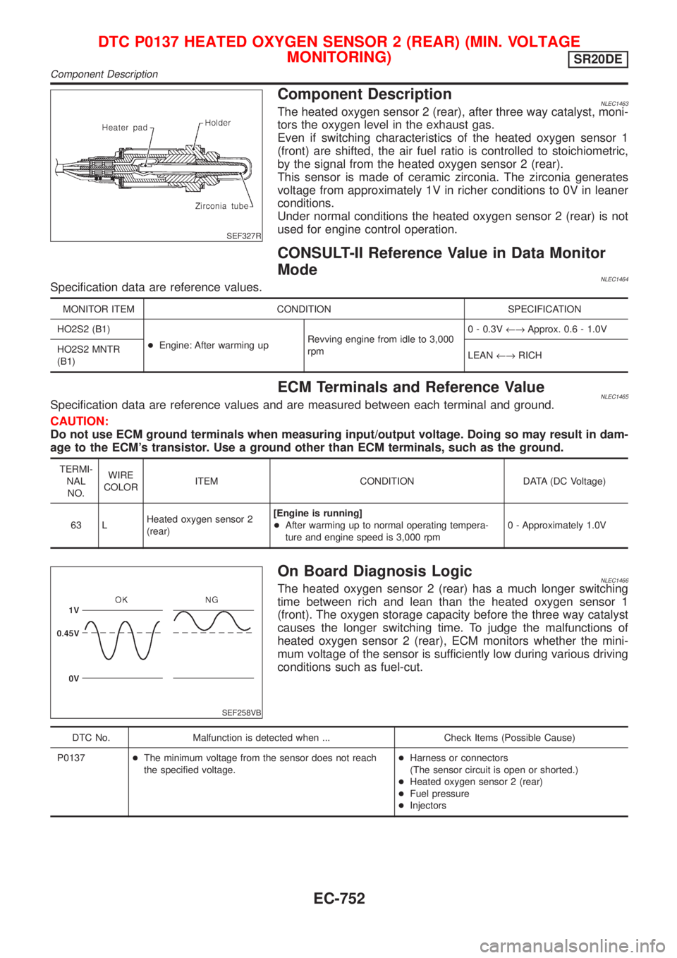
Component DescriptionNLEC1463The heated oxygen sensor 2 (rear), after three way catalyst, moni-
tors the oxygen level in the exhaust gas.
Even if switching characteristics of the heated oxygen sensor 1
(front) are shifted, the air fuel ratio is controlled to stoichiometric,
by the signal from the heated oxygen sensor 2 (rear).
This sensor is made of ceramic zirconia. The zirconia generates
voltage from approximately 1V in richer conditions to 0V in leaner
conditions.
Under normal conditions the heated oxygen sensor 2 (rear) is not
used for engine control operation.
CONSULT-II Reference Value in Data Monitor
Mode
NLEC1464Specification data are reference values.
MONITOR ITEM CONDITION SPECIFICATION
HO2S2 (B1)
+Engine: After warming upRevving engine from idle to 3,000
rpm0 - 0.3V¨Approx. 0.6 - 1.0V
HO2S2 MNTR
(B1)LEAN¨RICH
ECM Terminals and Reference ValueNLEC1465Specification data are reference values and are measured between each terminal and ground.
CAUTION:
Do not use ECM ground terminals when measuring input/output voltage. Doing so may result in dam-
age to the ECM's transistor. Use a ground other than ECM terminals, such as the ground.
TERMI-
NAL
NO.WIRE
COLORITEM CONDITION DATA (DC Voltage)
63 LHeated oxygen sensor 2
(rear)[Engine is running]
+After warming up to normal operating tempera-
ture and engine speed is 3,000 rpm0 - Approximately 1.0V
SEF258VB
On Board Diagnosis LogicNLEC1466The heated oxygen sensor 2 (rear) has a much longer switching
time between rich and lean than the heated oxygen sensor 1
(front). The oxygen storage capacity before the three way catalyst
causes the longer switching time. To judge the malfunctions of
heated oxygen sensor 2 (rear), ECM monitors whether the mini-
mum voltage of the sensor is sufficiently low during various driving
conditions such as fuel-cut.
DTC No. Malfunction is detected when ... Check Items (Possible Cause)
P0137+The minimum voltage from the sensor does not reach
the specified voltage.+Harness or connectors
(The sensor circuit is open or shorted.)
+Heated oxygen sensor 2 (rear)
+Fuel pressure
+Injectors
DTC P0137 HEATED OXYGEN SENSOR 2 (REAR) (MIN. VOLTAGE
MONITORING)
SR20DE
Component Description
EC-752
Page 1186 of 3051
SEF327R
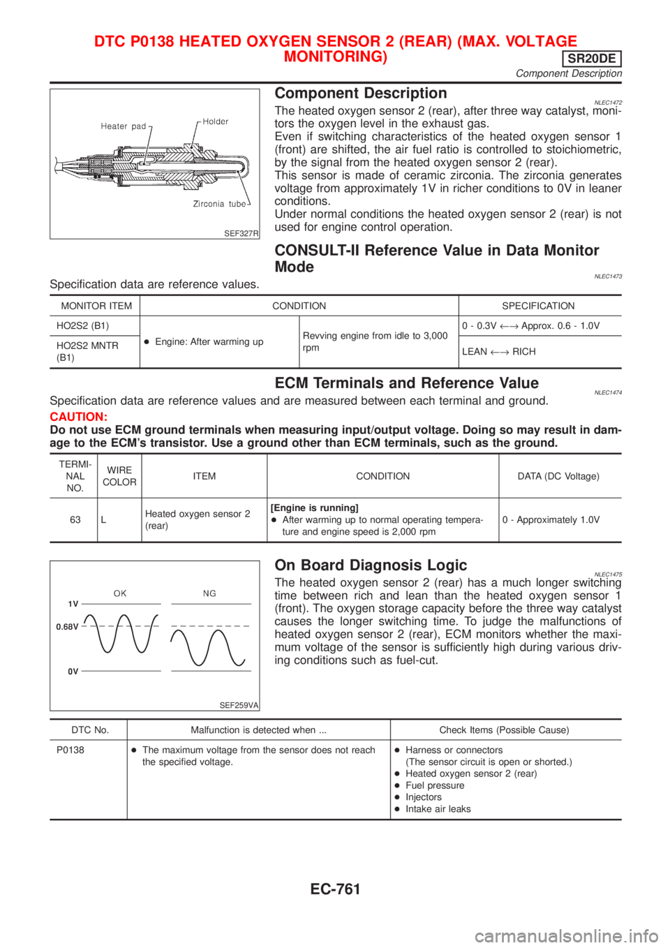
Component DescriptionNLEC1472The heated oxygen sensor 2 (rear), after three way catalyst, moni-
tors the oxygen level in the exhaust gas.
Even if switching characteristics of the heated oxygen sensor 1
(front) are shifted, the air fuel ratio is controlled to stoichiometric,
by the signal from the heated oxygen sensor 2 (rear).
This sensor is made of ceramic zirconia. The zirconia generates
voltage from approximately 1V in richer conditions to 0V in leaner
conditions.
Under normal conditions the heated oxygen sensor 2 (rear) is not
used for engine control operation.
CONSULT-II Reference Value in Data Monitor
Mode
NLEC1473Specification data are reference values.
MONITOR ITEM CONDITION SPECIFICATION
HO2S2 (B1)
+Engine: After warming upRevving engine from idle to 3,000
rpm0 - 0.3V¨Approx. 0.6 - 1.0V
HO2S2 MNTR
(B1)LEAN¨RICH
ECM Terminals and Reference ValueNLEC1474Specification data are reference values and are measured between each terminal and ground.
CAUTION:
Do not use ECM ground terminals when measuring input/output voltage. Doing so may result in dam-
age to the ECM's transistor. Use a ground other than ECM terminals, such as the ground.
TERMI-
NAL
NO.WIRE
COLORITEM CONDITION DATA (DC Voltage)
63 LHeated oxygen sensor 2
(rear)[Engine is running]
+After warming up to normal operating tempera-
ture and engine speed is 2,000 rpm0 - Approximately 1.0V
SEF259VA
On Board Diagnosis LogicNLEC1475The heated oxygen sensor 2 (rear) has a much longer switching
time between rich and lean than the heated oxygen sensor 1
(front). The oxygen storage capacity before the three way catalyst
causes the longer switching time. To judge the malfunctions of
heated oxygen sensor 2 (rear), ECM monitors whether the maxi-
mum voltage of the sensor is sufficiently high during various driv-
ing conditions such as fuel-cut.
DTC No. Malfunction is detected when ... Check Items (Possible Cause)
P0138+The maximum voltage from the sensor does not reach
the specified voltage.+Harness or connectors
(The sensor circuit is open or shorted.)
+Heated oxygen sensor 2 (rear)
+Fuel pressure
+Injectors
+Intake air leaks
DTC P0138 HEATED OXYGEN SENSOR 2 (REAR) (MAX. VOLTAGE
MONITORING)
SR20DE
Component Description
EC-761
Page 1195 of 3051
SEF327R
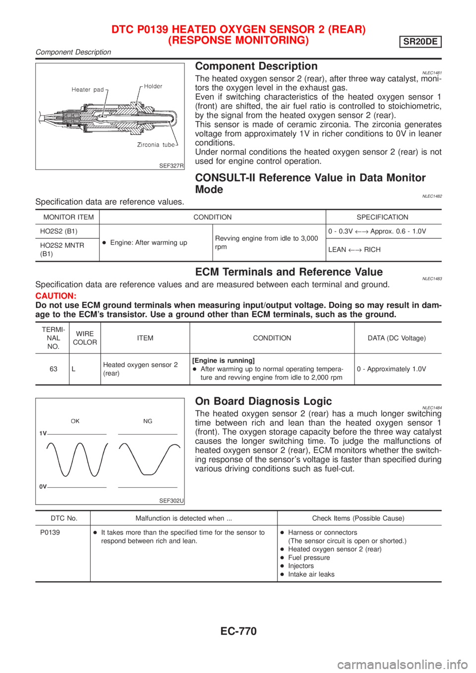
Component DescriptionNLEC1481The heated oxygen sensor 2 (rear), after three way catalyst, moni-
tors the oxygen level in the exhaust gas.
Even if switching characteristics of the heated oxygen sensor 1
(front) are shifted, the air fuel ratio is controlled to stoichiometric,
by the signal from the heated oxygen sensor 2 (rear).
This sensor is made of ceramic zirconia. The zirconia generates
voltage from approximately 1V in richer conditions to 0V in leaner
conditions.
Under normal conditions the heated oxygen sensor 2 (rear) is not
used for engine control operation.
CONSULT-II Reference Value in Data Monitor
Mode
NLEC1482Specification data are reference values.
MONITOR ITEM CONDITION SPECIFICATION
HO2S2 (B1)
+Engine: After warming upRevving engine from idle to 3,000
rpm0 - 0.3V¨Approx. 0.6 - 1.0V
HO2S2 MNTR
(B1)LEAN¨RICH
ECM Terminals and Reference ValueNLEC1483Specification data are reference values and are measured between each terminal and ground.
CAUTION:
Do not use ECM ground terminals when measuring input/output voltage. Doing so may result in dam-
age to the ECM's transistor. Use a ground other than ECM terminals, such as the ground.
TERMI-
NAL
NO.WIRE
COLORITEM CONDITION DATA (DC Voltage)
63 LHeated oxygen sensor 2
(rear)[Engine is running]
+After warming up to normal operating tempera-
ture and revving engine from idle to 2,000 rpm0 - Approximately 1.0V
SEF302U
On Board Diagnosis LogicNLEC1484The heated oxygen sensor 2 (rear) has a much longer switching
time between rich and lean than the heated oxygen sensor 1
(front). The oxygen storage capacity before the three way catalyst
causes the longer switching time. To judge the malfunctions of
heated oxygen sensor 2 (rear), ECM monitors whether the switch-
ing response of the sensor's voltage is faster than specified during
various driving conditions such as fuel-cut.
DTC No. Malfunction is detected when ... Check Items (Possible Cause)
P0139+It takes more than the specified time for the sensor to
respond between rich and lean.+Harness or connectors
(The sensor circuit is open or shorted.)
+Heated oxygen sensor 2 (rear)
+Fuel pressure
+Injectors
+Intake air leaks
DTC P0139 HEATED OXYGEN SENSOR 2 (REAR)
(RESPONSE MONITORING)
SR20DE
Component Description
EC-770