Page 1465 of 3051
Wiring DiagramNLEC1875
YEC715
POWER STEERING OIL PRESSURE SWITCHSR20DE
Wiring Diagram
EC-1040
Page 1466 of 3051
Diagnostic Procedure=NLEC1876
1 INSPECTION START
Do you have CONSULT-II?
YesorNo
Ye s©GO TO 2.
No©GO TO 3.
2 CHECK OVERALL FUNCTION
With CONSULT-II
1. Start engine.
2. Check ªPW/ST SIGNALº in ªDATA MONITORº mode with CONSULT-II under the following conditions.
SEF311Y
OK or NG
OK©INSPECTION END
NG©GO TO 4.
3 CHECK OVERALL FUNCTION
Without CONSULT-II
1. Start engine.
2. Check voltage between ECM terminal 46 and ground under the following conditions.
SEF614Y
OK or NG
OK©INSPECTION END
NG©GO TO 4.
POWER STEERING OIL PRESSURE SWITCHSR20DE
Diagnostic Procedure
EC-1041
Page 1467 of 3051
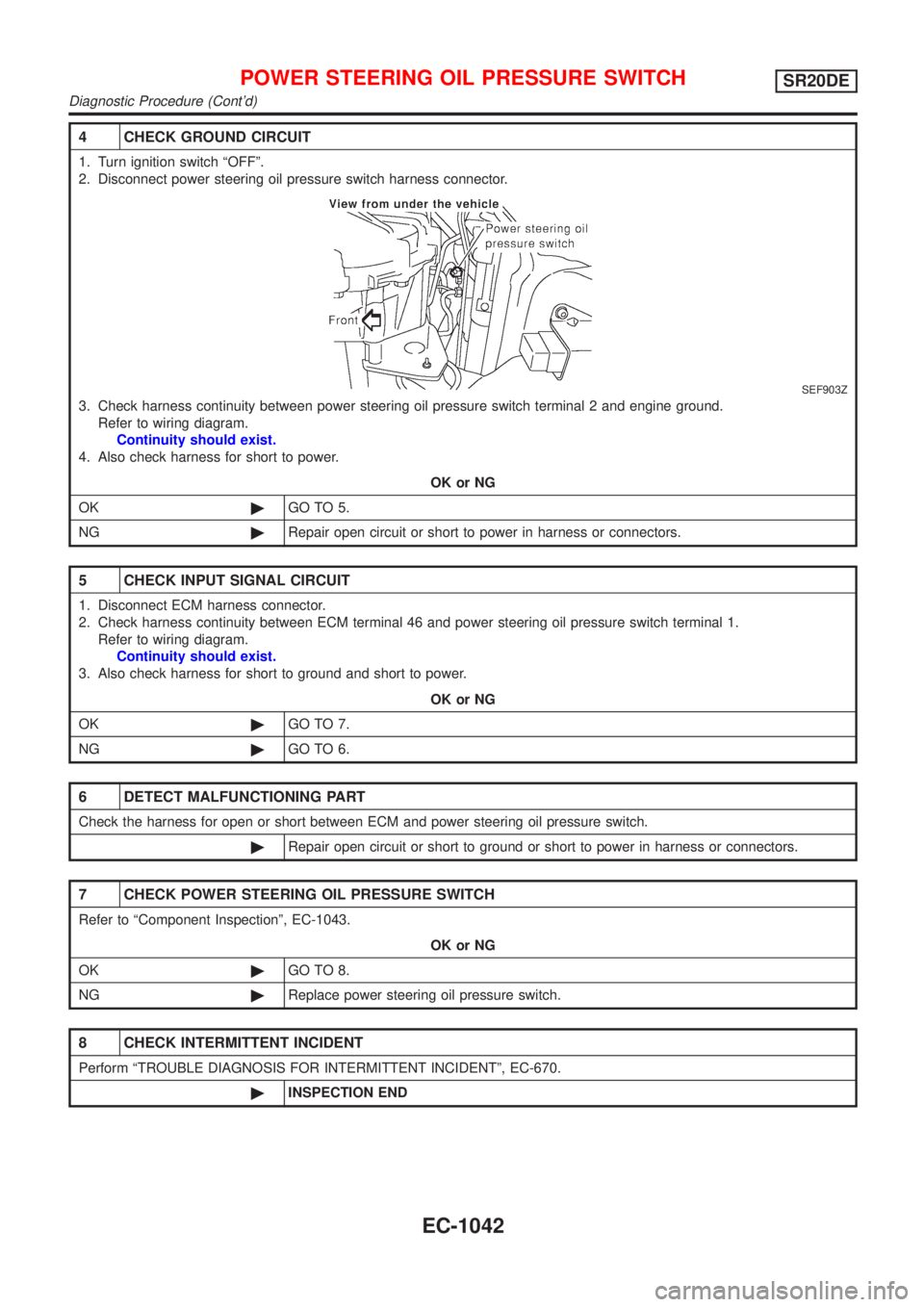
4 CHECK GROUND CIRCUIT
1. Turn ignition switch ªOFFº.
2. Disconnect power steering oil pressure switch harness connector.
SEF903Z
3. Check harness continuity between power steering oil pressure switch terminal 2 and engine ground.
Refer to wiring diagram.
Continuity should exist.
4. Also check harness for short to power.
OK or NG
OK©GO TO 5.
NG©Repair open circuit or short to power in harness or connectors.
5 CHECK INPUT SIGNAL CIRCUIT
1. Disconnect ECM harness connector.
2. Check harness continuity between ECM terminal 46 and power steering oil pressure switch terminal 1.
Refer to wiring diagram.
Continuity should exist.
3. Also check harness for short to ground and short to power.
OK or NG
OK©GO TO 7.
NG©GO TO 6.
6 DETECT MALFUNCTIONING PART
Check the harness for open or short between ECM and power steering oil pressure switch.
©Repair open circuit or short to ground or short to power in harness or connectors.
7 CHECK POWER STEERING OIL PRESSURE SWITCH
Refer to ªComponent Inspectionº, EC-1043.
OK or NG
OK©GO TO 8.
NG©Replace power steering oil pressure switch.
8 CHECK INTERMITTENT INCIDENT
Perform ªTROUBLE DIAGNOSIS FOR INTERMITTENT INCIDENTº, EC-670.
©INSPECTION END
POWER STEERING OIL PRESSURE SWITCHSR20DE
Diagnostic Procedure (Cont'd)
EC-1042
Page 1468 of 3051
Component InspectionNLEC1877POWER STEERING OIL PRESSURE SWITCHNLEC1877S011. Disconnect power steering oil pressure switch harness con-
nector then start engine.
2. Check continuity between terminals 1 and 2.
Refer to wiring diagram.
Conditions Continuity
Steering wheel is being fully turned. Yes
Steering wheel is not being turned. No
If NG, replace power steering oil pressure switch.
POWER STEERING OIL PRESSURE SWITCHSR20DE
Component Inspection
EC-1043
Page 1487 of 3051
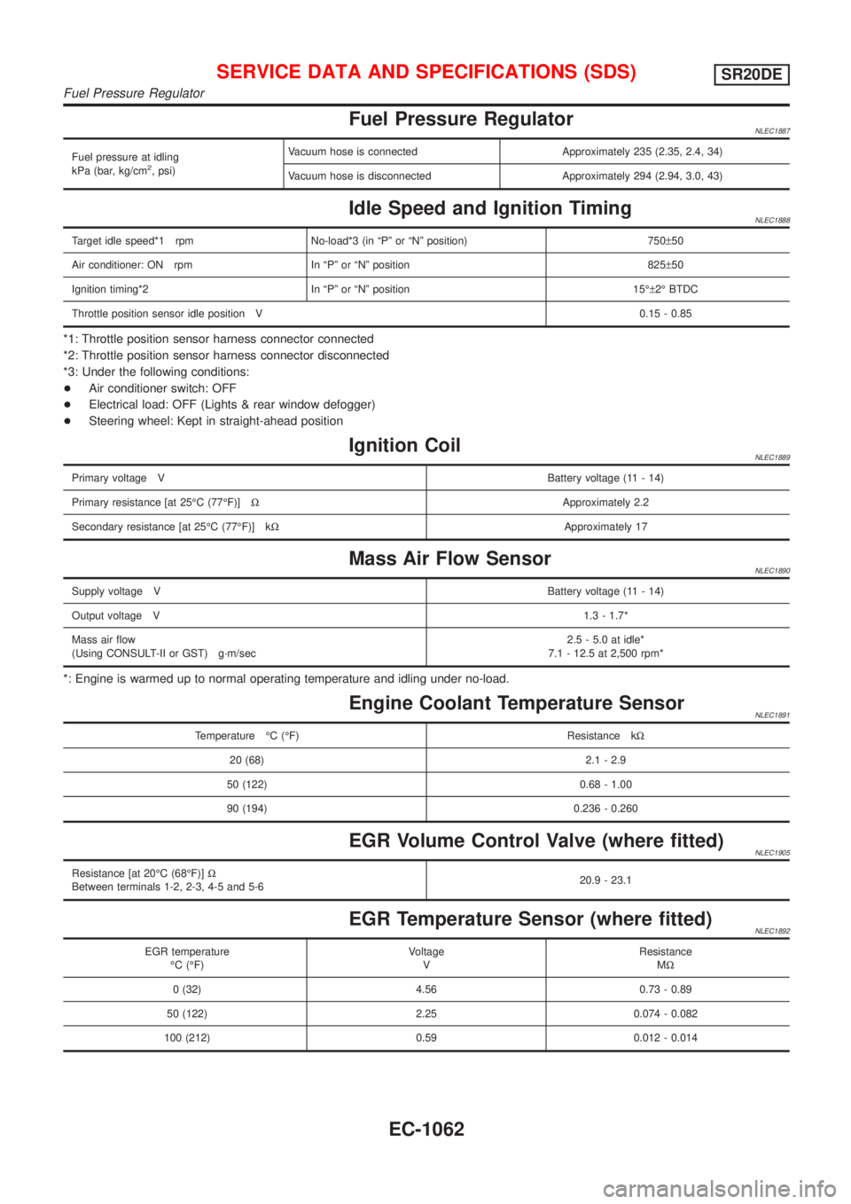
Fuel Pressure RegulatorNLEC1887
Fuel pressure at idling
kPa (bar, kg/cm2, psi)Vacuum hose is connected Approximately 235 (2.35, 2.4, 34)
Vacuum hose is disconnected Approximately 294 (2.94, 3.0, 43)
Idle Speed and Ignition TimingNLEC1888
Target idle speed*1 rpm No-load*3 (in ªPº or ªNº position) 750±50
Air conditioner: ON rpm In ªPº or ªNº position 825±50
Ignition timing*2 In ªPº or ªNº position 15ɱ2É BTDC
Throttle position sensor idle position V0.15 - 0.85
*1: Throttle position sensor harness connector connected
*2: Throttle position sensor harness connector disconnected
*3: Under the following conditions:
+Air conditioner switch: OFF
+Electrical load: OFF (Lights & rear window defogger)
+Steering wheel: Kept in straight-ahead position
Ignition CoilNLEC1889
Primary voltage VBattery voltage (11 - 14)
Primary resistance [at 25ÉC (77ÉF)]WApproximately 2.2
Secondary resistance [at 25ÉC (77ÉF)] kWApproximately 17
Mass Air Flow SensorNLEC1890
Supply voltage VBattery voltage (11 - 14)
Output voltage V1.3 - 1.7*
Mass air flow
(Using CONSULT-II or GST) g´m/sec2.5 - 5.0 at idle*
7.1 - 12.5 at 2,500 rpm*
*: Engine is warmed up to normal operating temperature and idling under no-load.
Engine Coolant Temperature SensorNLEC1891
Temperature ÉC (ÉF) Resistance kW
20 (68) 2.1 - 2.9
50 (122) 0.68 - 1.00
90 (194) 0.236 - 0.260
EGR Volume Control Valve (where fitted)NLEC1905
Resistance [at 20ÉC (68ÉF)]W
Between terminals 1-2, 2-3, 4-5 and 5-620.9 - 23.1
EGR Temperature Sensor (where fitted)NLEC1892
EGR temperature
ÉC (ÉF)Voltage
VResistance
MW
0 (32) 4.56 0.73 - 0.89
50 (122) 2.25 0.074 - 0.082
100 (212) 0.59 0.012 - 0.014
SERVICE DATA AND SPECIFICATIONS (SDS)SR20DE
Fuel Pressure Regulator
EC-1062
Page 1509 of 3051
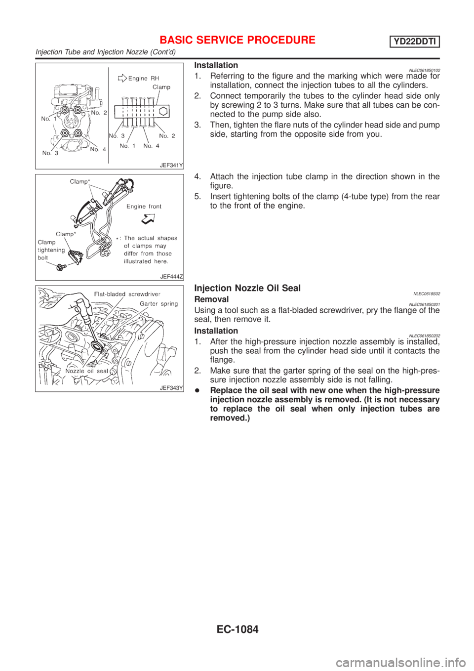
JEF341Y
InstallationNLEC0618S01021. Referring to the figure and the marking which were made for
installation, connect the injection tubes to all the cylinders.
2. Connect temporarily the tubes to the cylinder head side only
by screwing 2 to 3 turns. Make sure that all tubes can be con-
nected to the pump side also.
3. Then, tighten the flare nuts of the cylinder head side and pump
side, starting from the opposite side from you.
JEF444Z
4. Attach the injection tube clamp in the direction shown in the
figure.
5. Insert tightening bolts of the clamp (4-tube type) from the rear
to the front of the engine.
JEF343Y
Injection Nozzle Oil SealNLEC0618S02RemovalNLEC0618S0201Using a tool such as a flat-bladed screwdriver, pry the flange of the
seal, then remove it.
Installation
NLEC0618S02021. After the high-pressure injection nozzle assembly is installed,
push the seal from the cylinder head side until it contacts the
flange.
2. Make sure that the garter spring of the seal on the high-pres-
sure injection nozzle assembly side is not falling.
+Replace the oil seal with new one when the high-pressure
injection nozzle assembly is removed. (It is not necessary
to replace the oil seal when only injection tubes are
removed.)
BASIC SERVICE PROCEDUREYD22DDTI
Injection Tube and Injection Nozzle (Cont'd)
EC-1084
Page 1542 of 3051
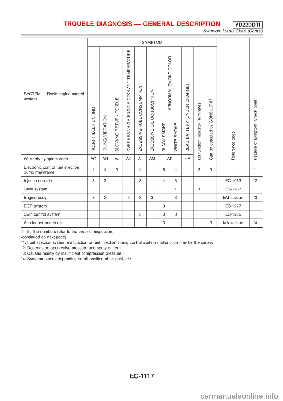
SYSTEM Ð Basic engine control
systemSYMPTOM
Reference page
Feature of symptom, Check pointROUGH IDLE/HUNTING
IDLING VIBRATION
SLOW/NO RETURN TO IDLE
OVERHEAT/HIGH ENGINE COOLANT TEMPERATURE
EXCESSIVE FUEL CONSUMPTION
EXCESSIVE OIL CONSUMPTION
ABNORMAL SMOKE COLOR
DEAD BATTERY (UNDER CHARGE)
Malfunction indicator illuminates.
Can be detected by CONSULT-II?BLACK SMOKE
WHITE SMOKEWarranty symptom code AG AH AJ AK AL AM AP HA
Electronic control fuel injection
pump mainframe44345433Ð*1
Injection nozzle 3 3 3 4 3 EC-1083 *2
Glow system 1 1 EC-1267
Engine body 3 3 3 3 3 3 EM section *3
EGR system 3 EC-1277
Swirl control system 3 3 3 EC-1285
Air cleaner and ducts 3 3 MA section *4
1 - 5: The numbers refer to the order of inspection.
(continued on next page)
*1: Fuel injection system malfunction or fuel injection timing control system malfunction may be the cause.
*2: Depends on open-valve pressure and spray pattern.
*3: Caused mainly by insufficient compression pressure.
*4: Symptom varies depending on off-position of air duct, etc.
TROUBLE DIAGNOSIS Ð GENERAL DESCRIPTIONYD22DDTI
Symptom Matrix Chart (Cont'd)
EC-1117
Page 1803 of 3051
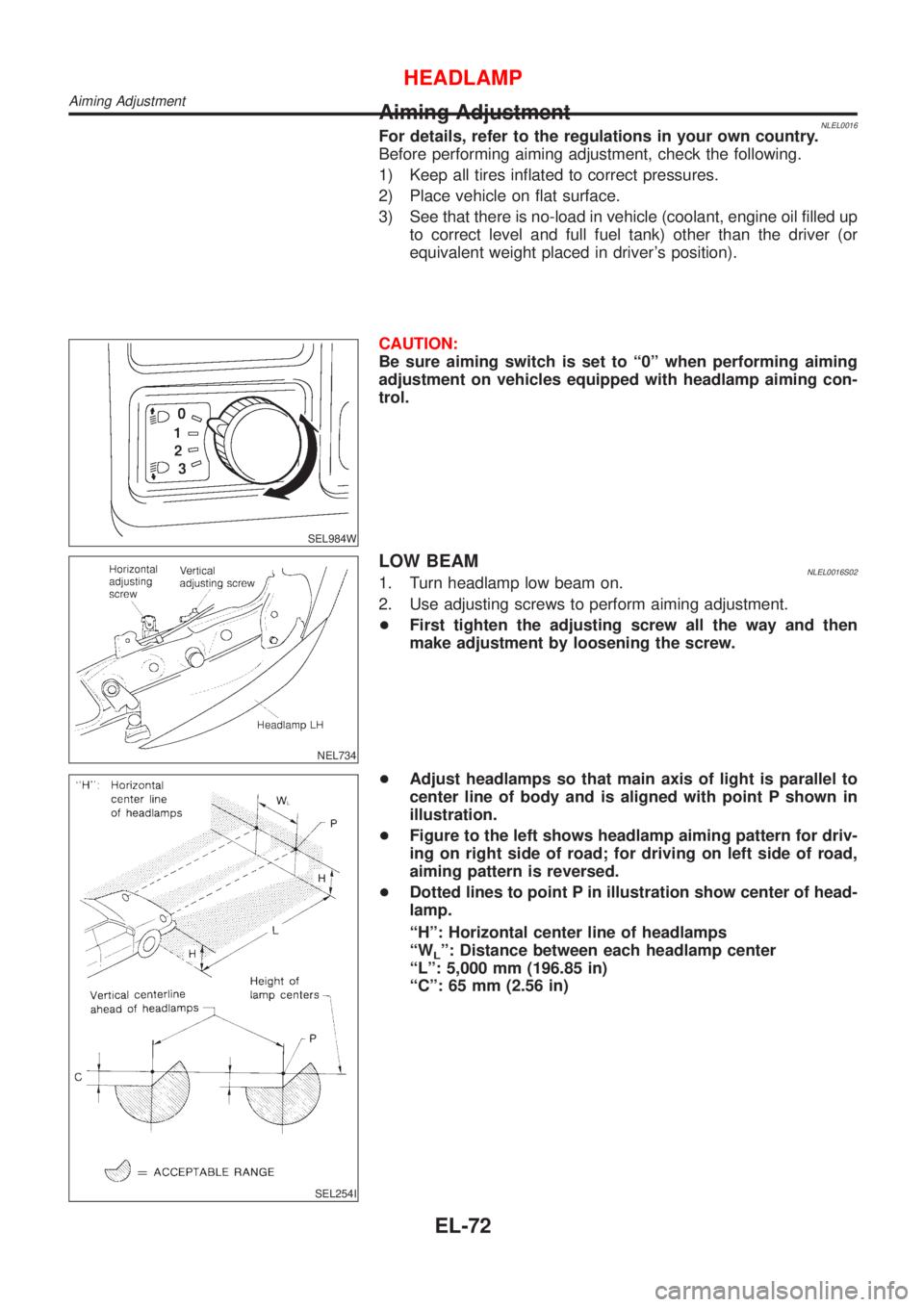
Aiming AdjustmentNLEL0016For details, refer to the regulations in your own country.
Before performing aiming adjustment, check the following.
1) Keep all tires inflated to correct pressures.
2) Place vehicle on flat surface.
3) See that there is no-load in vehicle (coolant, engine oil filled up
to correct level and full fuel tank) other than the driver (or
equivalent weight placed in driver's position).
SEL984W
CAUTION:
Be sure aiming switch is set to ª0º when performing aiming
adjustment on vehicles equipped with headlamp aiming con-
trol.
NEL734
LOW BEAMNLEL0016S021. Turn headlamp low beam on.
2. Use adjusting screws to perform aiming adjustment.
+First tighten the adjusting screw all the way and then
make adjustment by loosening the screw.
SEL254I
+Adjust headlamps so that main axis of light is parallel to
center line of body and is aligned with point P shown in
illustration.
+Figure to the left shows headlamp aiming pattern for driv-
ing on right side of road; for driving on left side of road,
aiming pattern is reversed.
+Dotted lines to point P in illustration show center of head-
lamp.
ªHº: Horizontal center line of headlamps
ªW
Lº: Distance between each headlamp center
ªLº: 5,000 mm (196.85 in)
ªCº: 65 mm (2.56 in)
HEADLAMP
Aiming Adjustment
EL-72