Page 2273 of 3051
NLEM0007
1. Warm up engine.
2. Turn ignition switch OFF.
3. Release fuel pressure.
Refer to EC-43, ªReleasing Fuel Pressureº.
4. Remove ignition coils.
5. Remove spark plugs.
+Clean area around plug with compressed air before removing
the spark plug.
SEM973E
AEM308
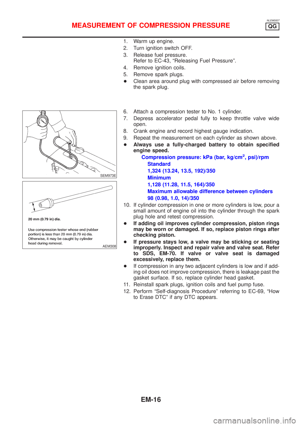
6. Attach a compression tester to No. 1 cylinder.
7. Depress accelerator pedal fully to keep throttle valve wide
open.
8. Crank engine and record highest gauge indication.
9. Repeat the measurement on each cylinder as shown above.
+Always use a fully-charged battery to obtain specified
engine speed.
Compression pressure: kPa (bar, kg/cm
2, psi)/rpm
Standard
1,324 (13.24, 13.5, 192)/350
Minimum
1,128 (11.28, 11.5, 164)/350
Maximum allowable difference between cylinders
98 (0.98, 1.0, 14)/350
10. If cylinder compression in one or more cylinders is low, pour a
small amount of engine oil into the cylinder through the spark
plug hole and retest compression.
+If adding oil improves cylinder compression, piston rings
may be worn or damaged. If so, replace piston rings after
checking piston.
+If pressure stays low, a valve may be sticking or seating
improperly. Inspect and repair valve and valve seat. Refer
to SDS, EM-70. If valve or valve seat is damaged
excessively, replace them.
+If compression in any two adjacent cylinders is low and if add-
ing oil does not improve compression, there is leakage past the
gasket surface. If so, replace cylinder head gasket.
11. Reinstall spark plugs, ignition coils and fuel pump fuse.
12. Perform ªSelf-diagnosis Procedureº referring to EC-69, ªHow
to Erase DTCº if any DTC appears.
MEASUREMENT OF COMPRESSION PRESSUREQG
EM-16
Page 2280 of 3051
CAUTION:
+After removing timing chain, do not turn crankshaft and
camshaft separately, or valves will strike piston heads.
+When installing chain tensioner, oil seals, or other sliding
parts, lubricate contacting surfaces with new engine oil.
+Apply new engine oil to bolt threads and seat surfaces
when installing camshaft sprocket and crankshaft pulley.
+When removing oil pump assembly, remove camshaft
position sensor (PHASE), then remove timing chain from
engine.
+Be careful not to damage sensor edges.
SEM869F
RemovalNLEM01051. Drain engine coolant from radiator and cylinder block.
Be careful not to spill coolant on drive belts.
2. Remove reservoir tank.
3. Release fuel pressure.
Refer to EC-43, ªFuel Pressure Releaseº.
4. Remove the following belts.
+Power steering pump drive belt
+Alternator drive belt
5. Remove front right-side wheel.
6. Remove front/right splash undercover.
7. Remove front exhaust tube.
SEM870F
8. Remove vacuum hoses, fuel hoses, and so on.
9. Remove ignition coils.
10. Remove spark plugs.
SEM102G
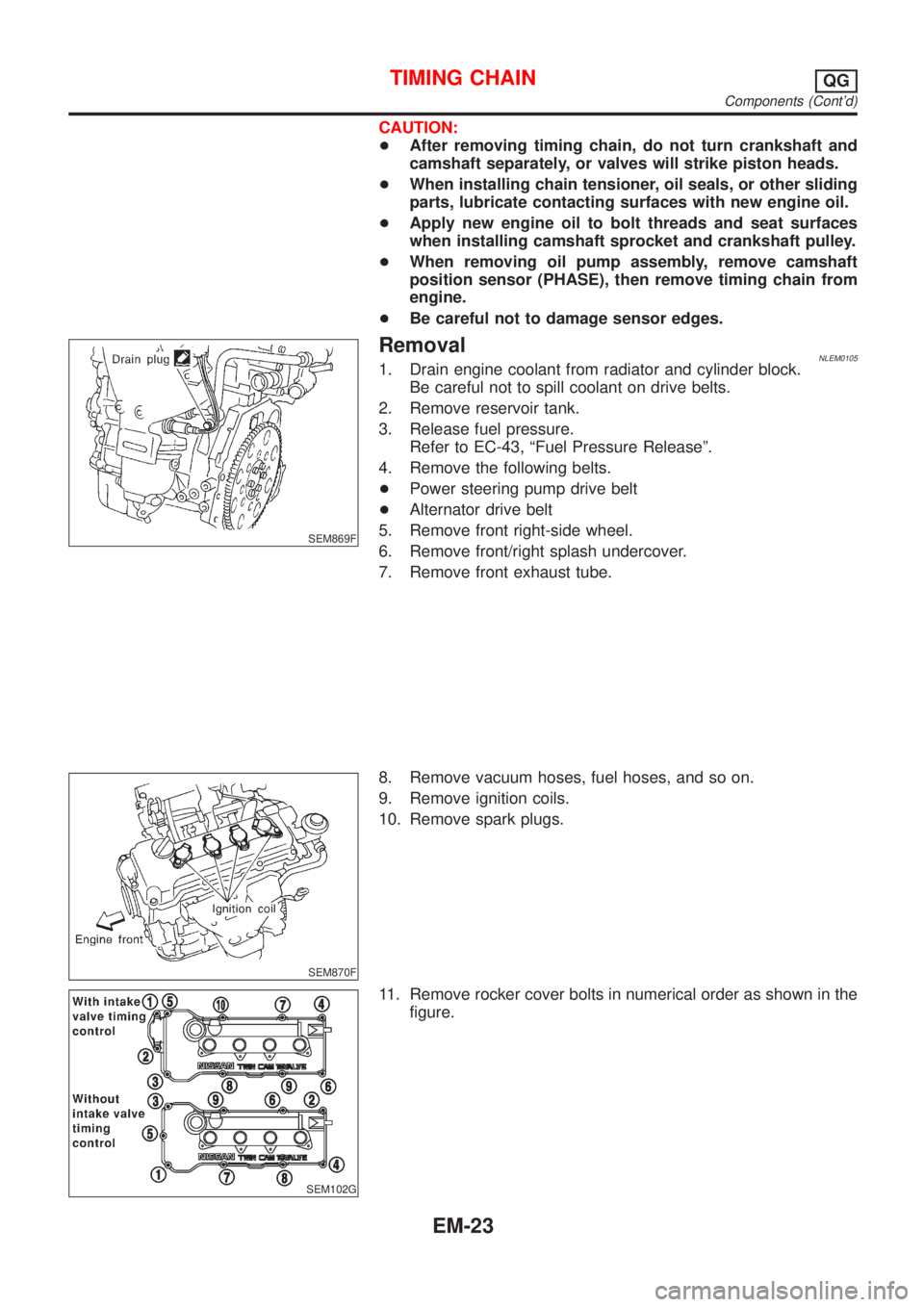
11. Remove rocker cover bolts in numerical order as shown in the
figure.
TIMING CHAINQG
Components (Cont'd)
EM-23
Page 2291 of 3051
CAUTION:
+When installing camshaft and oil seal, lubricate contacting
surfaces with new engine oil.
+When tightening cylinder head bolts, camshaft sprocket
bolts and camshaft bracket bolts, lubricate bolt threads
and seat surfaces with new engine oil.
+Attach tags to valve lifters so as not to mix them up.
SEM869F
RemovalNLEM00171. Drain engine coolant from radiator and cylinder block.
Be careful not to spill coolant on drive belts.
2. Release fuel pressure.
Refer to EC-43, ªFuel Pressure Releaseº.
3. Remove drive belts.
4. Remove air duct to intake manifold collector.
5. Remove front undercovers.
6. Remove front exhaust tube.
SEM870F
7. Disconnect vacuum hoses, fuel hoses, water hoses, wires,
harness, connectors and so on.
8. Remove intake manifold rear supports.
9. Remove exhaust manifold.
10. Remove ignition coils.
11. Remove spark plugs.
SEM102G
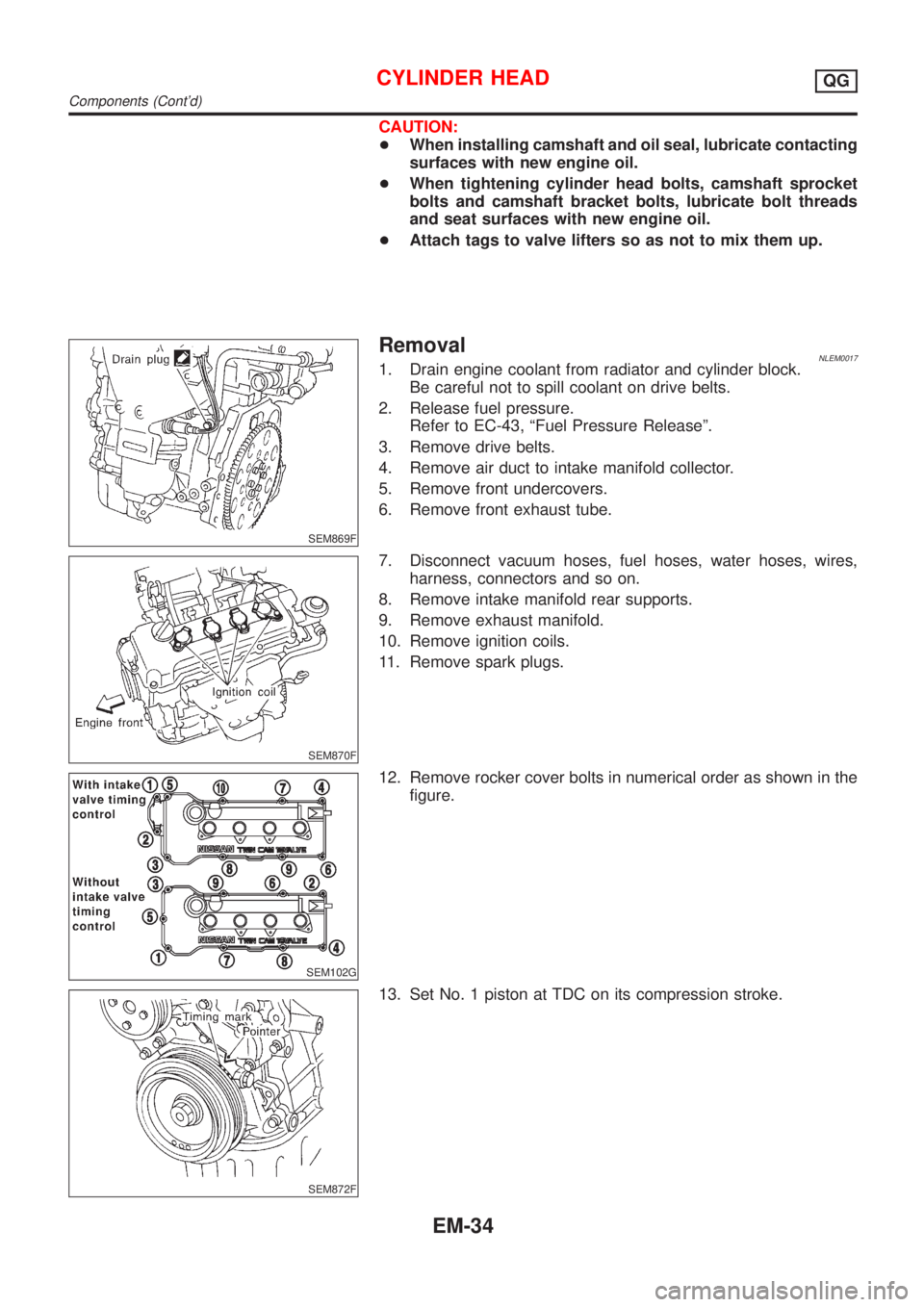
12. Remove rocker cover bolts in numerical order as shown in the
figure.
SEM872F
13. Set No. 1 piston at TDC on its compression stroke.
CYLINDER HEADQG
Components (Cont'd)
EM-34
Page 2307 of 3051
WARNING:
+Position vehicle on a flat and solid surface.
+Place chocks at front and back of rear wheels.
+Do not remove engine until exhaust system has com-
pletely cooled off, otherwise, you may burn yourself
and/or fire may break out in fuel line.
+Before disconnecting fuel hose, release pressure.
Refer to EC-43, ªFuel Pressure Releaseº.
+Be sure to lift engine and transaxle in a safe manner.
+For engines not equipped with engine slingers, attach
proper slingers and bolts described in PARTS CATALOG.
CAUTION:
+When lifting engine, be sure to clear surrounding parts.
Use special care near accelerator wire casing, brake lines
and brake master cylinder.
+When lifting the engine, always use engine slingers in a
safe manner.
+When removing drive shaft, be careful not to damage
grease seal of transaxle.
+Before separating engine and transaxle, remove crank-
shaft position sensor (POS) from the cylinder block
assembly.
+Always be extra careful not to damage edge of crankshaft
position sensor (POS), or signal plate teeth.
Engine cannot be removed separately from transaxle. Remove
engine with transaxle as an assembly.
REMOVALNLEM0022S011. Drain coolant from radiator and cylinder block. Refer to LC-18,
ªChanging Engine Coolantº.
2. Remove coolant reservoir tank and bracket.
3. Drain engine oil.
4. Remove battery and battery tray.
5. Remove air cleaner and air duct.
6. Remove drive belts.
7. Remove alternator and air conditioner compressor from
engine.
8. Remove power steering oil pump from engine and position
aside.
Power steering oil pump does not need to be disconnected
from power steering tubes.
ENGINE ASSEMBLYQG
Removal and Installation (Cont'd)
EM-50
Page 2321 of 3051
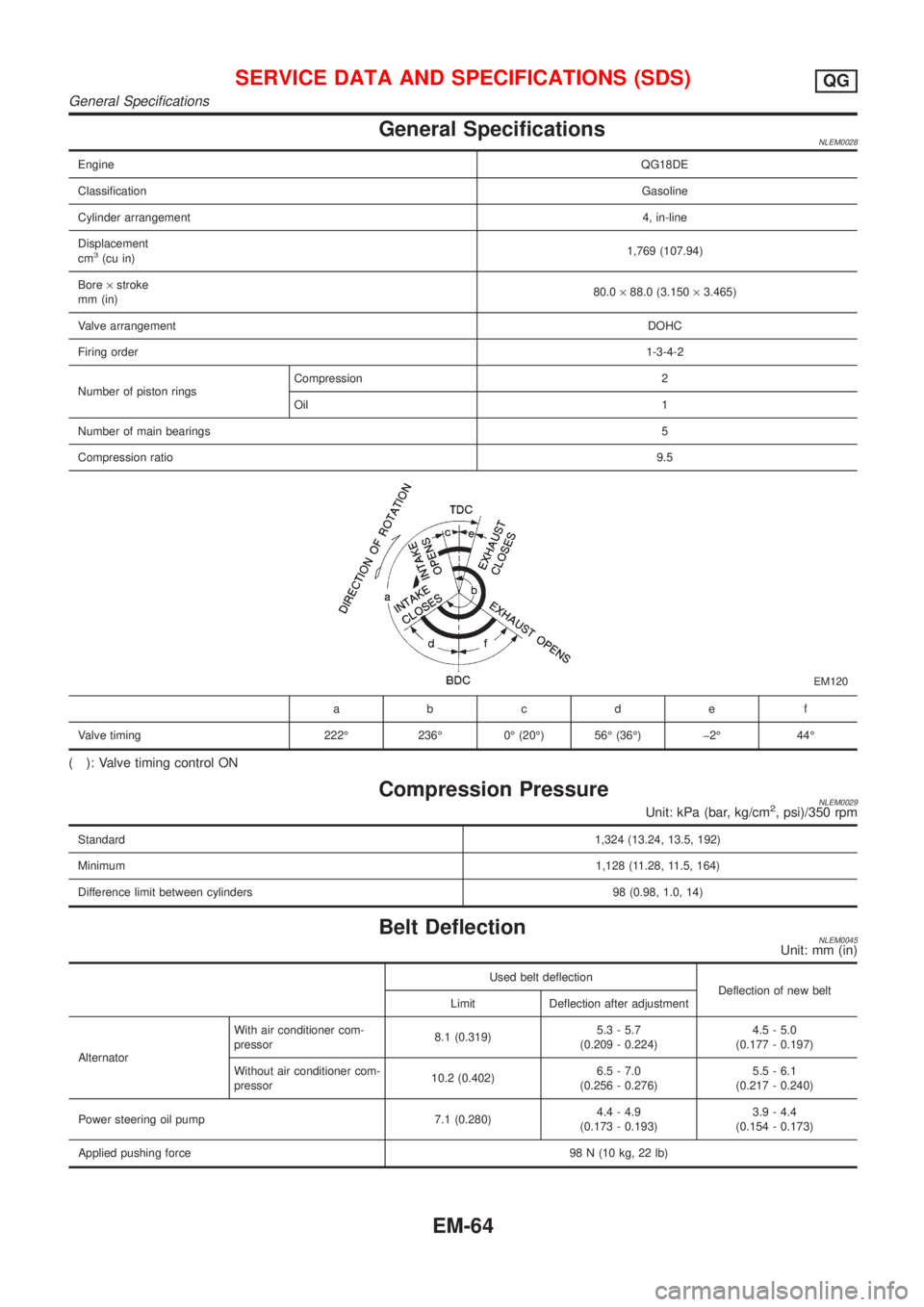
General SpecificationsNLEM0028
EngineQG18DE
ClassificationGasoline
Cylinder arrangement4, in-line
Displacement
cm
3(cu in)1,769 (107.94)
Bore´stroke
mm (in)80.0´88.0 (3.150´3.465)
Valve arrangementDOHC
Firing order1-3-4-2
Number of piston ringsCompression 2
Oil 1
Number of main bearings5
Compression ratio9.5
EM120
abcde f
Valve timing 222É 236É 0É (20É) 56É (36É) þ2É 44É
( ): Valve timing control ON
Compression PressureNLEM0029Unit: kPa (bar, kg/cm2, psi)/350 rpm
Standard1,324 (13.24, 13.5, 192)
Minimum1,128 (11.28, 11.5, 164)
Difference limit between cylinders 98 (0.98, 1.0, 14)
Belt DeflectionNLEM0045Unit: mm (in)
Used belt deflection
Deflection of new belt
Limit Deflection after adjustment
AlternatorWith air conditioner com-
pressor8.1 (0.319)5.3 - 5.7
(0.209 - 0.224)4.5 - 5.0
(0.177 - 0.197)
Without air conditioner com-
pressor10.2 (0.402)6.5 - 7.0
(0.256 - 0.276)5.5 - 6.1
(0.217 - 0.240)
Power steering oil pump 7.1 (0.280)4.4 - 4.9
(0.173 - 0.193)3.9 - 4.4
(0.154 - 0.173)
Applied pushing force98 N (10 kg, 22 lb)
SERVICE DATA AND SPECIFICATIONS (SDS)QG
General Specifications
EM-64
Page 2342 of 3051
NLEM0118
1. Warm up engine.
2. Turn ignition switch OFF.
3. Release fuel pressure.
Refer to EC-578, ªFuel Pressure Releaseº.
4. Remove all spark plugs.
5. Disconnect distributor coil connector.
SEM973E
SEM387C
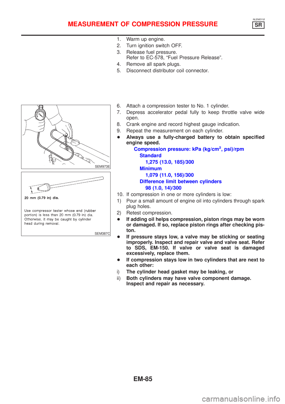
6. Attach a compression tester to No. 1 cylinder.
7. Depress accelerator pedal fully to keep throttle valve wide
open.
8. Crank engine and record highest gauge indication.
9. Repeat the measurement on each cylinder.
+Always use a fully-charged battery to obtain specified
engine speed.
Compression pressure: kPa (kg/cm
2, psi)/rpm
Standard
1,275 (13.0, 185)/300
Minimum
1,079 (11.0, 156)/300
Difference limit between cylinders
98 (1.0, 14)/300
10. If compression in one or more cylinders is low:
1) Pour a small amount of engine oil into cylinders through spark
plug holes.
2) Retest compression.
+If adding oil helps compression, piston rings may be worn
or damaged. If so, replace piston rings after checking pis-
ton.
+If pressure stays low, a valve may be sticking or seating
improperly. Inspect and repair valve and valve seat. Refer
to SDS, EM-150. If valve or valve seat is damaged
excessively, replace them.
+If compression stays low in two cylinders that are next to
each other:
i)The cylinder head gasket may be leaking, or
ii)Both cylinders may have valve component damage.
Inspect and repair as necessary.
MEASUREMENT OF COMPRESSION PRESSURESR
EM-85
Page 2362 of 3051
SEM077D
ReplacementNLEM0129VALVE OIL SEALNLEM0129S011. Remove accelerator wire.
2. Remove rocker cover.
3. Remove camshafts and sprockets. Refer to EM-109.
4. Remove spark plugs.
5. Install air hose adapter into spark plug hole and apply air
pressure to hold valves in place. Apply a pressure of 490 kPa
(5 kg/cm
2, 71 psi).
6. Remove rocker arm, rocker arm guide and shim.
SEM604E
7. Remove valve spring with Tool. Temporarily install camshaft as
shown.
Piston concerned should be set at TDC to prevent valve from
falling.
SEM054G
8. Remove valve oil seal with a suitable tool.
SEM358E
9. Apply new engine oil to new valve oil seal and install it with
Tool.
SEM997C
FRONT OIL SEALNLEM0129S021. Remove the following parts:
+Engine under cover
+Front RH wheel and engine side cover
+Drive belts
+Crankshaft pulley
2. Remove front oil seal.
+Be careful not to scratch front cover.
OIL SEALSR
Replacement
EM-105
Page 2378 of 3051
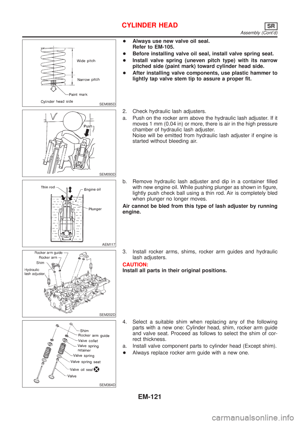
SEM085D
+Always use new valve oil seal.
Refer to EM-105.
+Before installing valve oil seal, install valve spring seat.
+Install valve spring (uneven pitch type) with its narrow
pitched side (paint mark) toward cylinder head side.
+After installing valve components, use plastic hammer to
lightly tap valve stem tip to assure a proper fit.
SEM093D
2. Check hydraulic lash adjusters.
a. Push on the rocker arm above the hydraulic lash adjuster. If it
moves 1 mm (0.04 in) or more, there is air in the high pressure
chamber of hydraulic lash adjuster.
Noise will be emitted from hydraulic lash adjuster if engine is
started without bleeding air.
AEM117
b. Remove hydraulic lash adjuster and dip in a container filled
with new engine oil. While pushing plunger as shown in figure,
lightly push check ball using a thin rod. Air is completely bled
when plunger no longer moves.
Air cannot be bled from this type of lash adjuster by running
engine.
SEM202D
3. Install rocker arms, shims, rocker arm guides and hydraulic
lash adjusters.
CAUTION:
Install all parts in their original positions.
SEM364D
4. Select a suitable shim when replacing any of the following
parts with a new one: Cylinder head, shim, rocker arm guide
and valve seat. Proceed as follows to select the shim of cor-
rect thickness.
a. Install valve component parts to cylinder head (Except shim).
+Always replace rocker arm guide with a new one.
CYLINDER HEADSR
Assembly (Cont'd)
EM-121