Page 2403 of 3051
General SpecificationsNLEM0143
Cylinder arrangementIn-line 4
Displacement cm
3(cu in)1,998 (121.92)
Bore and stroke mm (in)86´86 (3.39´3.39)
Valve arrangementDOHC
Firing order1-3-4-2
Number of piston ringsCompression 2
Oil 1
Number of main bearings5
Compression ratio10.0
Valve timing
Unit: degree
EM120
abcde f
232É 240É 6É 54É 3É 49É
Compression PressureNLEM0144Unit: kPa (kg/cm2, psi)/300 rpm
Compression pressureStandard 1,275 (13.01, 184.9)
Minimum 1,079 (11.01, 156.5)
Differential limit between cylinders 98 (1.0, 14)
Cylinder HeadNLEM0147Unit: mm (in)
SEM043F
Standard Limit
Head surface distortion Less than 0.03 (0.0012) 0.1 (0.004)
Nominal cylinder head
height ªHº136.9 - 137.1 (5.390 - 5.398)
Resurfacing limit 0.2 (0.008)*
*Total amount of cylinder head resurfacing plus cylinder block resurfacing
SERVICE DATA AND SPECIFICATIONS (SDS)SR
General Specifications
EM-146
Page 2453 of 3051
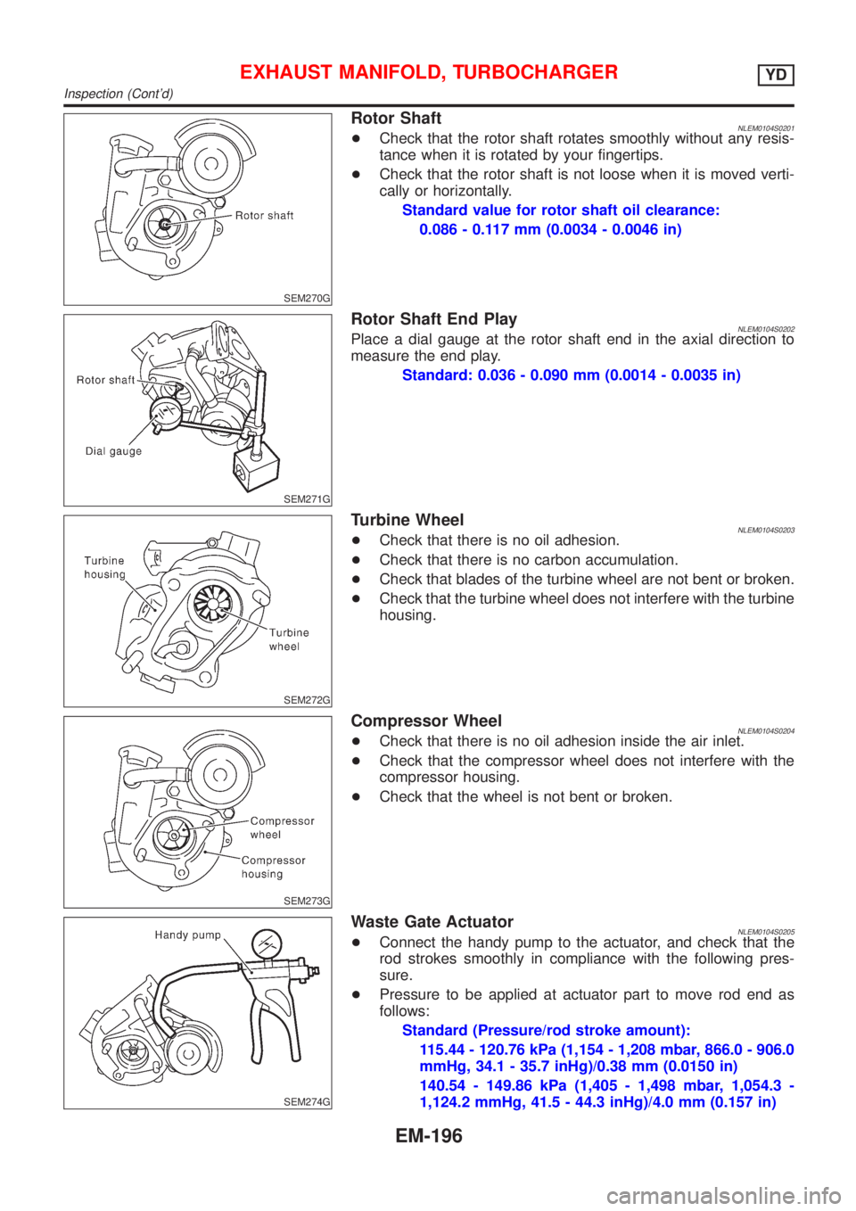
SEM270G
Rotor ShaftNLEM0104S0201+Check that the rotor shaft rotates smoothly without any resis-
tance when it is rotated by your fingertips.
+Check that the rotor shaft is not loose when it is moved verti-
cally or horizontally.
Standard value for rotor shaft oil clearance:
0.086 - 0.117 mm (0.0034 - 0.0046 in)
SEM271G
Rotor Shaft End PlayNLEM0104S0202Place a dial gauge at the rotor shaft end in the axial direction to
measure the end play.
Standard: 0.036 - 0.090 mm (0.0014 - 0.0035 in)
SEM272G
Turbine WheelNLEM0104S0203+Check that there is no oil adhesion.
+Check that there is no carbon accumulation.
+Check that blades of the turbine wheel are not bent or broken.
+Check that the turbine wheel does not interfere with the turbine
housing.
SEM273G
Compressor WheelNLEM0104S0204+Check that there is no oil adhesion inside the air inlet.
+Check that the compressor wheel does not interfere with the
compressor housing.
+Check that the wheel is not bent or broken.
SEM274G
Waste Gate ActuatorNLEM0104S0205+Connect the handy pump to the actuator, and check that the
rod strokes smoothly in compliance with the following pres-
sure.
+Pressure to be applied at actuator part to move rod end as
follows:
Standard (Pressure/rod stroke amount):
115.44 - 120.76 kPa (1,154 - 1,208 mbar, 866.0 - 906.0
mmHg, 34.1 - 35.7 inHg)/0.38 mm (0.0150 in)
140.54 - 149.86 kPa (1,405 - 1,498 mbar, 1,054.3 -
1,124.2 mmHg, 41.5 - 44.3 inHg)/4.0 mm (0.157 in)
EXHAUST MANIFOLD, TURBOCHARGERYD
Inspection (Cont'd)
EM-196
Page 2454 of 3051
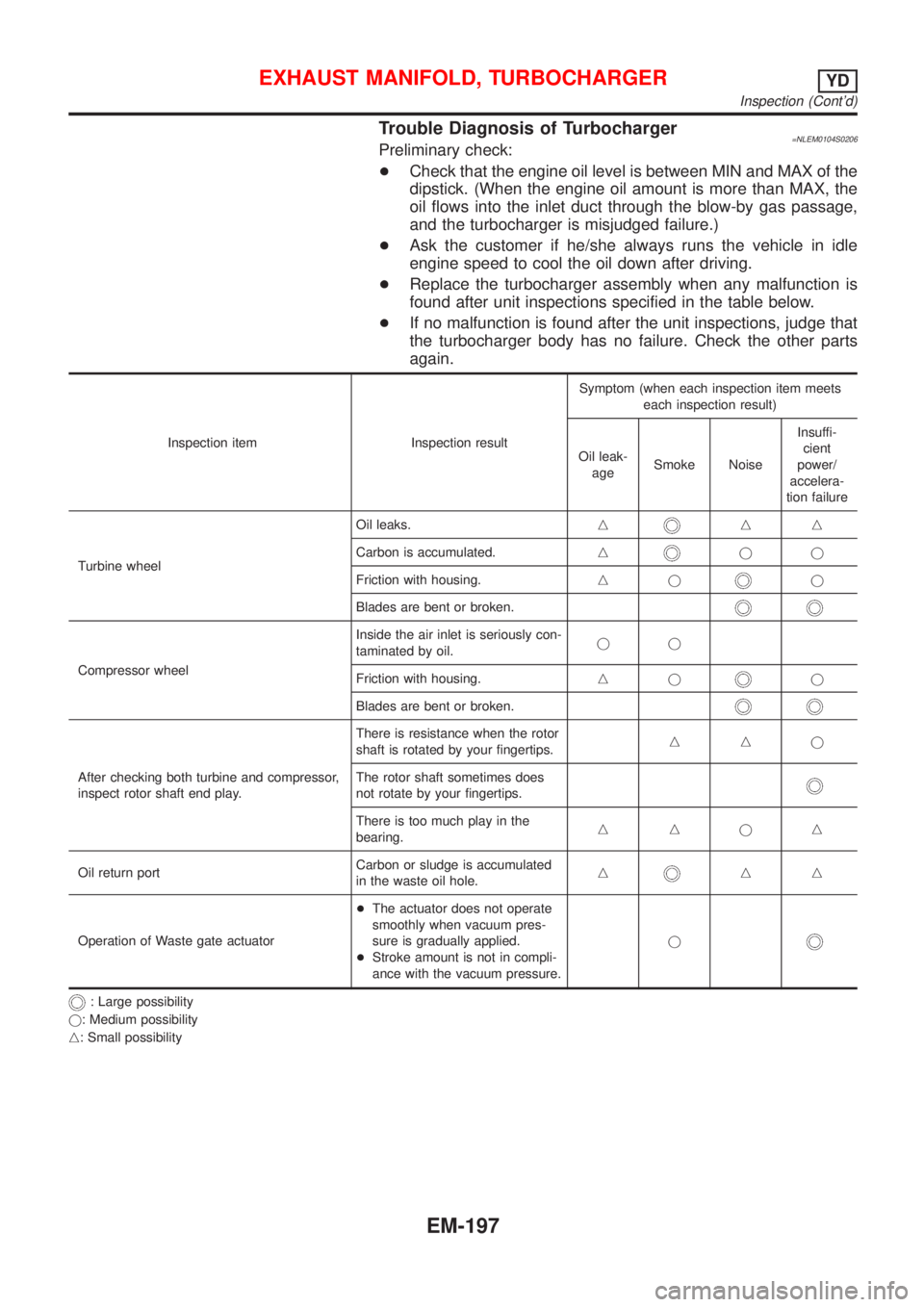
Trouble Diagnosis of Turbocharger=NLEM0104S0206Preliminary check:
+Check that the engine oil level is between MIN and MAX of the
dipstick. (When the engine oil amount is more than MAX, the
oil flows into the inlet duct through the blow-by gas passage,
and the turbocharger is misjudged failure.)
+Ask the customer if he/she always runs the vehicle in idle
engine speed to cool the oil down after driving.
+Replace the turbocharger assembly when any malfunction is
found after unit inspections specified in the table below.
+If no malfunction is found after the unit inspections, judge that
the turbocharger body has no failure. Check the other parts
again.
Inspection item Inspection resultSymptom (when each inspection item meets
each inspection result)
Oil leak-
ageSmoke NoiseInsuffi-
cient
power/
accelera-
tion failure
Turbine wheelOil leaks.n
nn
Carbon is accumulated.n
jj
Friction with housing.nj
j
Blades are bent or broken.
Compressor wheelInside the air inlet is seriously con-
taminated by oil.jj
Friction with housing.njj
Blades are bent or broken.
After checking both turbine and compressor,
inspect rotor shaft end play.There is resistance when the rotor
shaft is rotated by your fingertips.nnj
The rotor shaft sometimes does
not rotate by your fingertips.
There is too much play in the
bearing.nnjn
Oil return portCarbon or sludge is accumulated
in the waste oil hole.n
nn
Operation of Waste gate actuator+The actuator does not operate
smoothly when vacuum pres-
sure is gradually applied.
+Stroke amount is not in compli-
ance with the vacuum pressure.j
: Large possibility
j: Medium possibility
n: Small possibility
EXHAUST MANIFOLD, TURBOCHARGERYD
Inspection (Cont'd)
EM-197
Page 2458 of 3051
CAUTION:
+When installing camshafts, chain tensioners, oil seals, or
other sliding parts, lubricate contacting surfaces with new
engine oil.
+Apply new engine oil to threads and seat surfaces when
installing cylinder head, camshaft sprocket, crankshaft
pulley, and camshaft bracket.
+Attach tags to valve lifters so as not to mix them up.
RemovalNLEM0063PREPARATIVE WORKNLEM0063S011. Drain engine coolant. Refer to LC-59, ªChanging Engine Cool-
antº.
2. Remove exhaust manifold. Refer to EM-193, ªRemovalº.
3. Remove intake manifold. Refer to EM-189, ªRemovalº.
+Apply paint to camshaft sprockets for alignment during
installation.
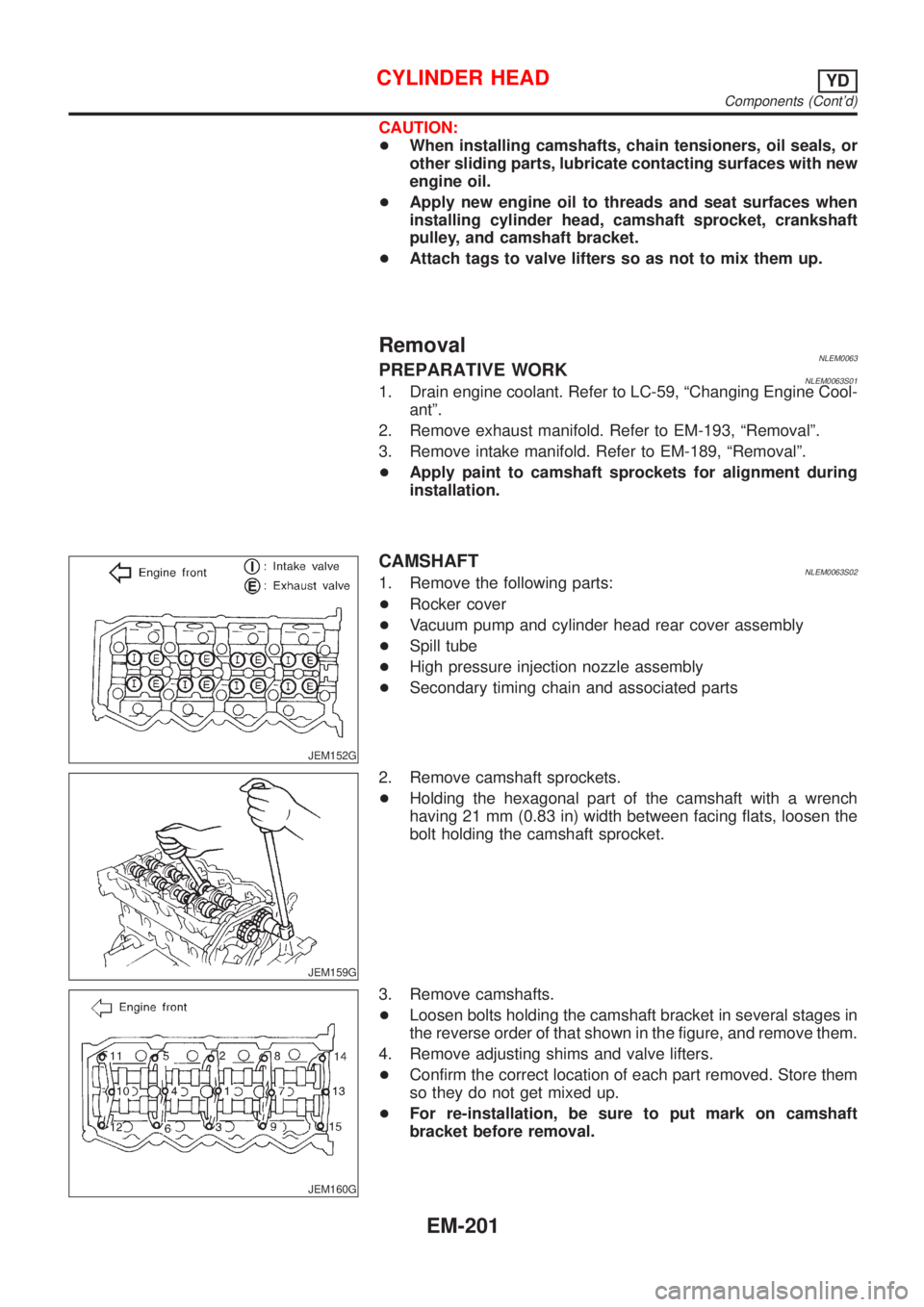
JEM152G
CAMSHAFTNLEM0063S021. Remove the following parts:
+Rocker cover
+Vacuum pump and cylinder head rear cover assembly
+Spill tube
+High pressure injection nozzle assembly
+Secondary timing chain and associated parts
JEM159G
2. Remove camshaft sprockets.
+Holding the hexagonal part of the camshaft with a wrench
having 21 mm (0.83 in) width between facing flats, loosen the
bolt holding the camshaft sprocket.
JEM160G
3. Remove camshafts.
+Loosen bolts holding the camshaft bracket in several stages in
the reverse order of that shown in the figure, and remove them.
4. Remove adjusting shims and valve lifters.
+Confirm the correct location of each part removed. Store them
so they do not get mixed up.
+For re-installation, be sure to put mark on camshaft
bracket before removal.
CYLINDER HEADYD
Components (Cont'd)
EM-201
Page 2463 of 3051
SEM008A
VALVE GUIDE REPLACEMENTNLEM0065S09+When a valve guide is removed, replace with an oversized [0.2
mm (0.008 in)] valve guide.
1. To remove valve guide, heat cylinder head to 110 to 130ÉC
(230 to 266ÉF) by soaking in heated oil.
SEM931C
2. Drive out valve guide with a press [under a 20 kN (2 ton, 2.2
US ton, 2.0 Imp ton) pressure] or hammer and suitable tool.
SEM932C
3. Ream cylinder head valve guide hole.
Valve guide hole diameter (for service parts):
10.175 - 10.196 mm (0.4006 - 0.4014 in)
JEM156G
4. Heat cylinder head to 110 to 130ÉC (230 to 266ÉF) and press
service valve guide onto cylinder head.
Projection ªLº:
10.4 - 10.6 mm (0.409 - 0.417 in)
5. Ream valve guide.
Finished size:
6.000 - 6.018 mm (0.2362 - 0.2369 in)
CYLINDER HEADYD
Inspection (Cont'd)
EM-206
Page 2480 of 3051
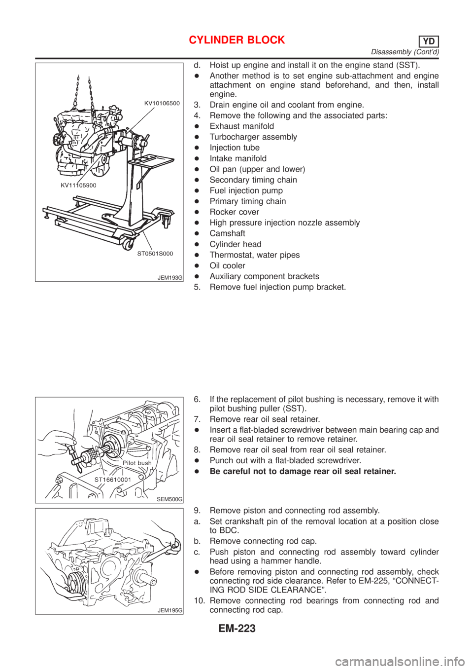
JEM193G
d. Hoist up engine and install it on the engine stand (SST).
+Another method is to set engine sub-attachment and engine
attachment on engine stand beforehand, and then, install
engine.
3. Drain engine oil and coolant from engine.
4. Remove the following and the associated parts:
+Exhaust manifold
+Turbocharger assembly
+Injection tube
+Intake manifold
+Oil pan (upper and lower)
+Secondary timing chain
+Fuel injection pump
+Primary timing chain
+Rocker cover
+High pressure injection nozzle assembly
+Camshaft
+Cylinder head
+Thermostat, water pipes
+Oil cooler
+Auxiliary component brackets
5. Remove fuel injection pump bracket.
SEM500G
6. If the replacement of pilot bushing is necessary, remove it with
pilot bushing puller (SST).
7. Remove rear oil seal retainer.
+Insert a flat-bladed screwdriver between main bearing cap and
rear oil seal retainer to remove retainer.
8. Remove rear oil seal from rear oil seal retainer.
+Punch out with a flat-bladed screwdriver.
+Be careful not to damage rear oil seal retainer.
JEM195G
9. Remove piston and connecting rod assembly.
a. Set crankshaft pin of the removal location at a position close
to BDC.
b. Remove connecting rod cap.
c. Push piston and connecting rod assembly toward cylinder
head using a hammer handle.
+Before removing piston and connecting rod assembly, check
connecting rod side clearance. Refer to EM-225, ªCONNECT-
ING ROD SIDE CLEARANCEº.
10. Remove connecting rod bearings from connecting rod and
connecting rod cap.
CYLINDER BLOCKYD
Disassembly (Cont'd)
EM-223
Page 2498 of 3051
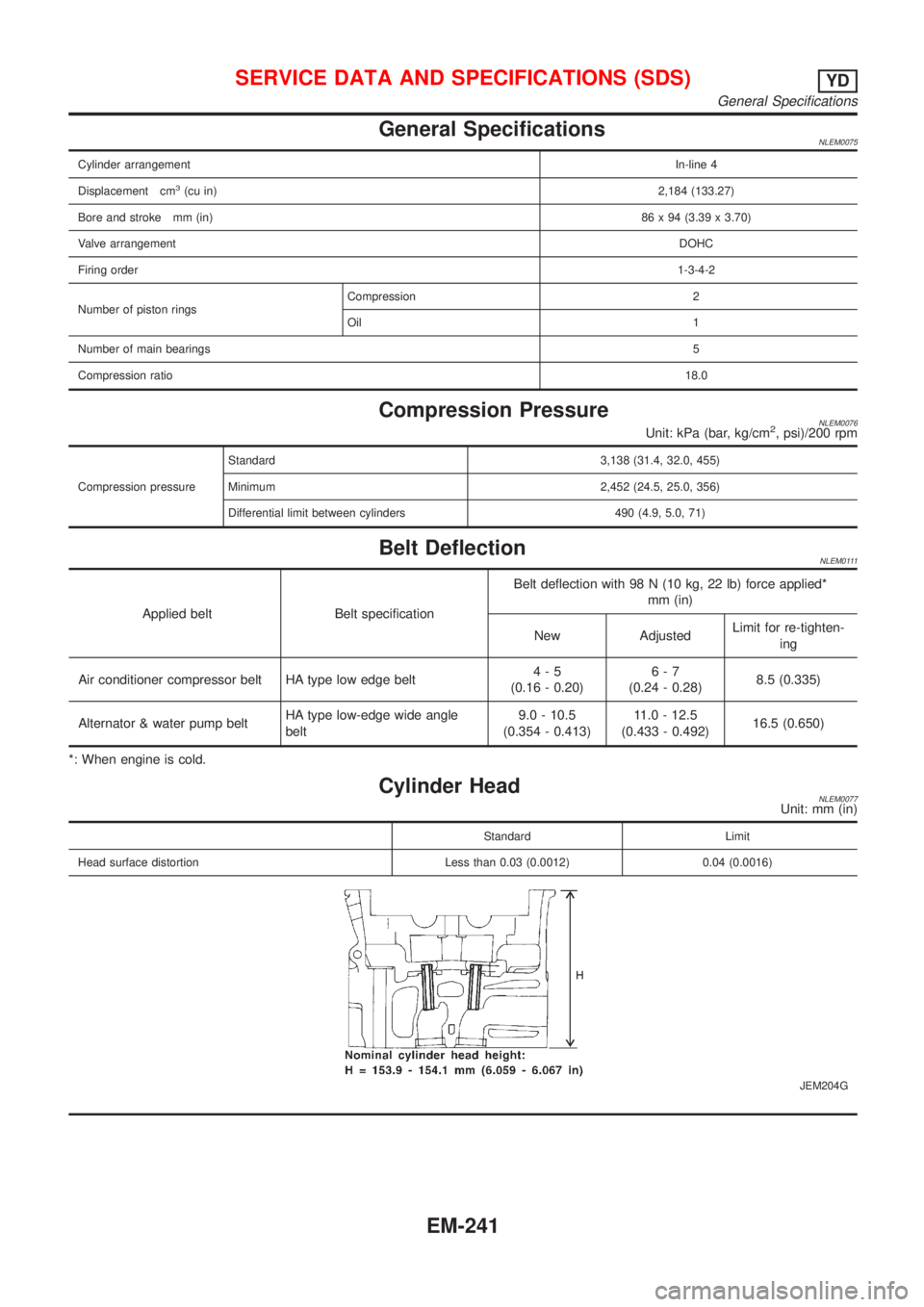
General SpecificationsNLEM0075
Cylinder arrangementIn-line 4
Displacement cm
3(cu in)2,184 (133.27)
Bore and stroke mm (in)86 x 94 (3.39 x 3.70)
Valve arrangementDOHC
Firing order1-3-4-2
Number of piston ringsCompression 2
Oil 1
Number of main bearings5
Compression ratio18.0
Compression PressureNLEM0076Unit: kPa (bar, kg/cm2, psi)/200 rpm
Compression pressureStandard 3,138 (31.4, 32.0, 455)
Minimum 2,452 (24.5, 25.0, 356)
Differential limit between cylinders 490 (4.9, 5.0, 71)
Belt DeflectionNLEM0111
Applied belt Belt specificationBelt deflection with 98 N (10 kg, 22 lb) force applied*
mm (in)
New AdjustedLimit for re-tighten-
ing
Air conditioner compressor belt HA type low edge belt4-5
(0.16 - 0.20)6-7
(0.24 - 0.28)8.5 (0.335)
Alternator & water pump beltHA type low-edge wide angle
belt9.0 - 10.5
(0.354 - 0.413)11.0 - 12.5
(0.433 - 0.492)16.5 (0.650)
*: When engine is cold.
Cylinder HeadNLEM0077Unit: mm (in)
Standard Limit
Head surface distortion Less than 0.03 (0.0012) 0.04 (0.0016)
JEM204G
SERVICE DATA AND SPECIFICATIONS (SDS)YD
General Specifications
EM-241
Page 2597 of 3051
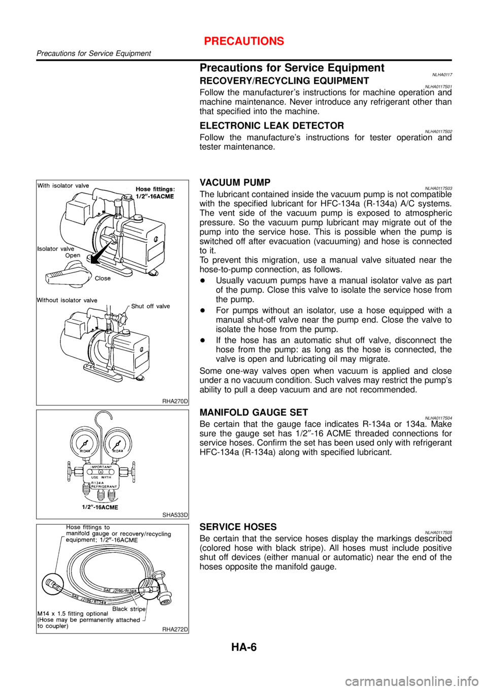
Precautions for Service EquipmentNLHA0117RECOVERY/RECYCLING EQUIPMENTNLHA0117S01Follow the manufacturer’s instructions for machine operation and
machine maintenance. Never introduce any refrigerant other than
that specified into the machine.
ELECTRONIC LEAK DETECTORNLHA0117S02Follow the manufacture’s instructions for tester operation and
tester maintenance.
RHA270D
VACUUM PUMPNLHA0117S03The lubricant contained inside the vacuum pump is not compatible
with the specified lubricant for HFC-134a (R-134a) A/C systems.
The vent side of the vacuum pump is exposed to atmospheric
pressure. So the vacuum pump lubricant may migrate out of the
pump into the service hose. This is possible when the pump is
switched off after evacuation (vacuuming) and hose is connected
to it.
To prevent this migration, use a manual valve situated near the
hose-to-pump connection, as follows.
+Usually vacuum pumps have a manual isolator valve as part
of the pump. Close this valve to isolate the service hose from
the pump.
+For pumps without an isolator, use a hose equipped with a
manual shut-off valve near the pump end. Close the valve to
isolate the hose from the pump.
+If the hose has an automatic shut off valve, disconnect the
hose from the pump: as long as the hose is connected, the
valve is open and lubricating oil may migrate.
Some one-way valves open when vacuum is applied and close
under a no vacuum condition. Such valves may restrict the pump’s
ability to pull a deep vacuum and are not recommended.
SHA533D
MANIFOLD GAUGE SETNLHA0117S04Be certain that the gauge face indicates R-134a or 134a. Make
sure the gauge set has 1/2″-16 ACME threaded connections for
service hoses. Confirm the set has been used only with refrigerant
HFC-134a (R-134a) along with specified lubricant.
RHA272D
SERVICE HOSESNLHA0117S05Be certain that the service hoses display the markings described
(colored hose with black stripe). All hoses must include positive
shut off devices (either manual or automatic) near the end of the
hoses opposite the manifold gauge.
PRECAUTIONS
Precautions for Service Equipment
HA-6