Page 2580 of 3051
Dimensions=NLGI0008S03Unit: mm (in)
Item
Overall length 4,270 (168.1)
Overall width 1,760 (69.3)
Overall height 1,610 (63.4)
Front tread 1,535 (60.4)
Rear tread 1,510 (59.4)
Wheelbase 2,535 (99.8)
Wheels and TiresNLGI0008S04
Road
wheelSteel 15×6J
——
Offset mm (in) 40 (1.57)
Aluminium
—15×6J 16×6.5JJ
Offset mm (in) 40 (1.57) 45 (1.77)
Tire sizeConventional 195/65 R15 195/65 R15 205/55 R16
Spare*1Conven-
tional*2Conven-
tional*2Conven-
tional*2
*1: Without spare tire in case of NISSAN Mobility System (NMS)
*2: T125/90D16 for models with QG18DE engine
IDENTIFICATION INFORMATION
Dimensions
GI-41
Page 2703 of 3051

Vehicle speed sensor (VSS) . EC-338, 858, 1172
Viscosity number (SAE) ............................ MA-21
Viscous coupling (FF M/T) ........................ MT-63
W
WARN - Wiring diagram .......................... EL-156
WIP/R - Wiring diagram .......................... EL-184
WIPER - Wiring diagram ......................... EL-178
Warning chime ......................................... EL-165
Warning lamps ......................................... EL-155
Washer, front ........................................... EL-176
Water pump ................................... LC-14, 33, 55
Water temperature gauge ........................ EL-130
Weatherstrip - See Exterior ....................... BT-38
Wheel alignment (rear) ............................. SU-19
Wheel bearing (front) .................................. AX-3Wheel bearing (rear) ................................. AX-22
Wheel hub (front) ........................................ AX-5
Wheel hub (rear) ....................................... AX-23
Wheel sensors (ABS) ............................... BR-90
Wheelarch height ........................................ SU-6
Wheelbase (Dimensions) ........................... GI-41
Wide open & closed throttle position
switch .......................................... EC-175, 700
Width (Dimensions) .................................... GI-41
Window, rear .............................................. BT-59
Windshield ................................................. BT-59
Wiper, front .............................................. EL-176
Wiring diagram (cell code) list ................. EL-525
Wiring diagrams .......................................... GI-11
Withdrawal lever (clutch) ..................... CL-17, 20
Wrist pin - See Piston pin inspection ...... EM-54,
134, 226
ALPHABETICAL INDEX
IDX-8
Page 2752 of 3051
![NISSAN ALMERA TINO 2001 Service Repair Manual JLC290B
REMOVALNLLC0076S011. Using a socket wrench [plane-to-plane width: 17 mm (0.67 in)],
loosen the filter body approximately four turns.
JLC291B
2. Drain the oil after matching the ªDRAINº arrow](/manual-img/5/57352/w960_57352-2751.png "NISSAN ALMERA TINO 2001 Service Repair Manual JLC290B
REMOVALNLLC0076S011. Using a socket wrench [plane-to-plane width: 17 mm (0.67 in)],
loosen the filter body approximately four turns.
JLC291B
2. Drain the oil after matching the ªDRAINº arrow")
JLC290B
REMOVALNLLC0076S011. Using a socket wrench [plane-to-plane width: 17 mm (0.67 in)],
loosen the filter body approximately four turns.
JLC291B
2. Drain the oil after matching the ªDRAINº arrow mark at the
bottom of the filter body to the protrusion on the oil filter
bracket.
+Catch the oil with a pan or cloth.
CAUTION:
+The drained oil flows over the right surface of the filter
body.
+Completely wipe clean any engine oil remaining on the
filter body or vehicle.
3. Remove the filter body, then remove the oil filter element.
JLC292B
4. Remove the O-ring from the filter body.
+Push the O-ring in one direction, lift the slack part using
fingers, and remove the O-ring from the filter body.
CAUTION:
Do not use wires or flat-bladed screwdrivers etc. as they may
cause damage to the filter body.
INSTALLATIONNLLC0076S021. Completely remove all foreign objects adhering to the inside of
the filter body or O-ring mounting area (body side and bracket
side).
2. Install the oil filter element and O-ring to the filter body.
+Push the oil filter element into the filter body completely.
3. Install the filter body to the oil filter bracket.
: 20 - 24 N´m (2.0 - 2.5 kg-m, 15 - 18 ft-lb)
4. After warming up the engine, check for engine oil leakage.
ENGINE LUBRICATION SYSTEMYD
Changing Oil Filter (Cont'd)
LC-49
Page 2840 of 3051
SMT801D
Shift Control Components
INSPECTION=NLMT0066+Check if the width of shift fork hook (sliding area with coupling
sleeve) is within allowable specification below.
ItemOne-side wear specifi-
cationSliding width of new part
1st & 2nd 0.2 mm (0.008 in)7.80 - 7.93 mm
(0.3071 - 0.3122 in)
3rd & 4th 0.2 mm (0.008 in)7.80 - 7.93 mm
(0.3071 - 0.3122 in)
5th & reverse 0.2 mm (0.008 in)7.80 - 7.93 mm
(0.3071 - 0.3122 in)
SMT692D
+Check if shift check groove of fork rod or 5th & reverse check
groove is worn, or has any other abnormalities.
REPAIR FOR COMPONENT PARTSRS5F70A
Shift Control Components
MT-51
Page 2872 of 3051
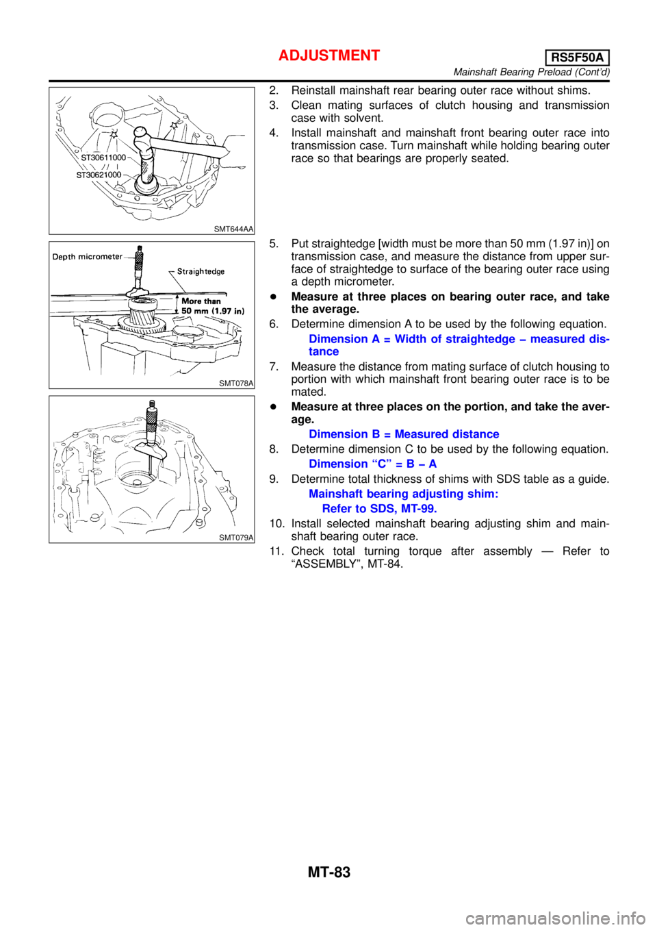
SMT644AA
2. Reinstall mainshaft rear bearing outer race without shims.
3. Clean mating surfaces of clutch housing and transmission
case with solvent.
4. Install mainshaft and mainshaft front bearing outer race into
transmission case. Turn mainshaft while holding bearing outer
race so that bearings are properly seated.
SMT078A
SMT079A
5. Put straightedge [width must be more than 50 mm (1.97 in)] on
transmission case, and measure the distance from upper sur-
face of straightedge to surface of the bearing outer race using
a depth micrometer.
+Measure at three places on bearing outer race, and take
the average.
6. Determine dimension A to be used by the following equation.
Dimension A = Width of straightedge measured dis-
tance
7. Measure the distance from mating surface of clutch housing to
portion with which mainshaft front bearing outer race is to be
mated.
+Measure at three places on the portion, and take the aver-
age.
Dimension B = Measured distance
8. Determine dimension C to be used by the following equation.
Dimension “C”=BA
9. Determine total thickness of shims with SDS table as a guide.
Mainshaft bearing adjusting shim:
Refer to SDS, MT-99.
10. Install selected mainshaft bearing adjusting shim and main-
shaft bearing outer race.
11. Check total turning torque after assembly—Refer to
“ASSEMBLY”, MT-84.
ADJUSTMENTRS5F50A
Mainshaft Bearing Preload (Cont’d)
MT-83