Page 91 of 3051

DescriptionNLAT0041The engine speed signal is sent from the ECM to the TCM.
TCM TERMINALS AND REFERENCE VALUENLAT0041S01Remarks: Specification data are reference values.
Terminal
No.Wire color Item ConditionJudgement stan-
dard (Approx.)
39 L/OREngine speed sig-
nal
When engine runs at idle speed. 0.5 - 1.5V
ON BOARD DIAGNOSIS LOGICNLAT0041S02
Diagnostic trouble code Malfunction is detected when ... Check item (Possible cause)
: ENGINE SPEED SIG
TCM does not receive the proper voltage
signal from ECM.+Harness or connectors
(The sensor circuit is open or shorted.)
: P0725
: MI Code No. 0725
SAT250K
SAT255K
DIAGNOSTIC TROUBLE CODE (DTC) CONFIRMATION
PROCEDURE
NLAT0041S03CAUTION:
Always drive vehicle at a safe speed.
NOTE:
If ªDIAGNOSTIC TROUBLE CODE CONFIRMATION PROCE-
DUREº has been previously conducted, always turn ignition
switch ªOFFº and wait at least 5 seconds before conducting
the next test.
After the repair, perform the following procedure to confirm the
malfunction is eliminated.
With CONSULT-II
1) Turn ignition switch ªONº and select ªDATA MONITORº mode
for ªENGINEº with CONSULT-II.
2) Start engine and maintain the following conditions for at least
10 consecutive seconds.
VHCL SPEED SE: 10 km/h (6 MPH) or more
THRTL POS SEN: More than 1.3V
Selector lever: D position
If the check result is ªNGº, go to ªDiagnostic Procedureº, AT-92
With GST
Follow the procedure ªWith CONSULT-IIº.
DTC P0725 ENGINE SPEED SIGNALEURO-OBD
Description
AT-90
Page 93 of 3051
Diagnostic ProcedureNLAT0042
1 CHECK DTC WITH ECM
Perform diagnostic test mode II (self-diag results) for engine control. Check ignition signal circuit condition.
OK or NG
OK (With CONSULT-II)©GO TO 2.
OK (Without CONSULT-
II)©GO TO 3.
NG©Check ignition signal circuit for engine control. Refer to EC section (IGNITION SIGNAL).
2 CHECK INPUT SIGNAL (With CONSULT-II)
With CONSULT-II
1. Start engine.
2. Select ªTCM INPUT SIGNALSº in ªDATA MONITORº mode for ªCVTº with CONSULT-II.
3. Read out the value of ªENGINE SPEEDº.
Check engine speed changes according to throttle position.
OK or NG
OK©GO TO 4.
NG©Check the following items:
+Harness for short or open between TCM and ECM
+Resistor and ignition coil
Refer to EC section (IGNITION SIGNAL).
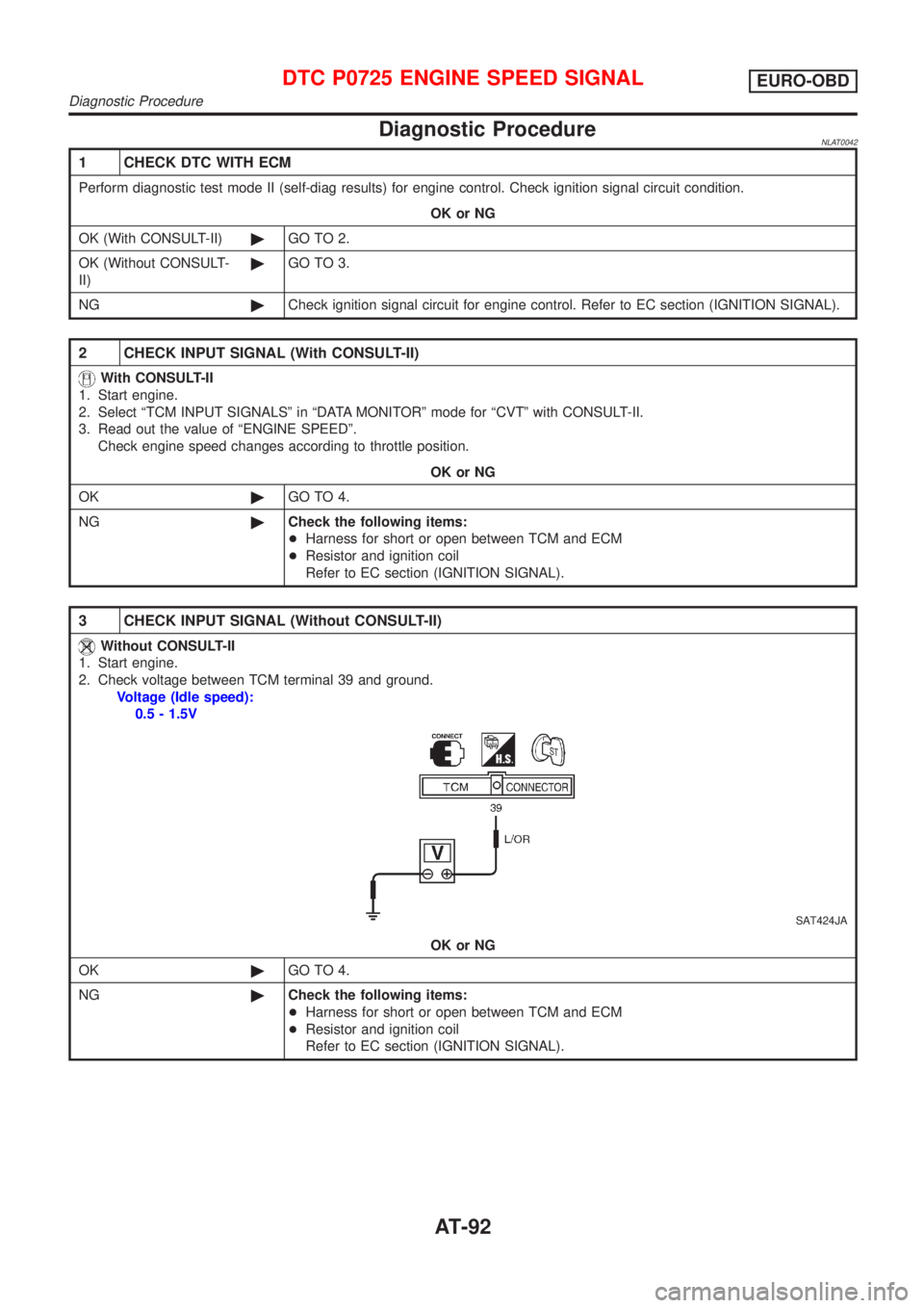
3 CHECK INPUT SIGNAL (Without CONSULT-II)
Without CONSULT-II
1. Start engine.
2. Check voltage between TCM terminal 39 and ground.
Voltage (Idle speed):
0.5 - 1.5V
SAT424JA
OK or NG
OK©GO TO 4.
NG©Check the following items:
+Harness for short or open between TCM and ECM
+Resistor and ignition coil
Refer to EC section (IGNITION SIGNAL).
DTC P0725 ENGINE SPEED SIGNALEURO-OBD
Diagnostic Procedure
AT-92
Page 95 of 3051
DescriptionNLAT0055The torque converter clutch solenoid valve is activated by the TCM
in response to signals sent from the vehicle speed and throttle
position sensors. Lock-up piston operation will then be controlled.
Lock-up operation, however, is prohibited when CVT fluid tempera-
ture is too low.
When the accelerator pedal is depressed (less than 2/8) in lock-up
condition, the engine speed should not change abruptly. If there is
a big jump in engine speed, there is no lock-up.
CONSULT-II REFERENCE VALUE IN DATA MONITOR
MODE
NLAT0055S01Remarks: Specification data are reference values.
Monitor item Condition Specification
Torque converter clutch solenoid valve
dutyLock-up ªOFFº
¯
Lock-up ªONºApproximately 4%
¯
Approximately 94%
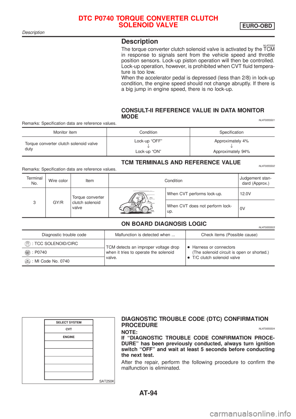
TCM TERMINALS AND REFERENCE VALUENLAT0055S02Remarks: Specification data are reference values.
Terminal
No.Wire color Item ConditionJudgement stan-
dard (Approx.)
3 GY/RTorque converter
clutch solenoid
valve
When CVT performs lock-up. 12.0V
When CVT does not perform lock-
up.0V
ON BOARD DIAGNOSIS LOGICNLAT0055S03
Diagnostic trouble code Malfunction is detected when ... Check items (Possible cause)
: TCC SOLENOID/CIRC
TCM detects an improper voltage drop
when it tries to operate the solenoid
valve.+Harness or connectors
(The solenoid circuit is open or shorted.)
+T/C clutch solenoid valve
: P0740
: MI Code No. 0740
SAT250K
DIAGNOSTIC TROUBLE CODE (DTC) CONFIRMATION
PROCEDURE
NLAT0055S04NOTE:
If ªDIAGNOSTIC TROUBLE CODE CONFIRMATION PROCE-
DUREº has been previously conducted, always turn ignition
switch ªOFFº and wait at least 5 seconds before conducting
the next test.
After the repair, perform the following procedure to confirm the
malfunction is eliminated.
DTC P0740 TORQUE CONVERTER CLUTCH
SOLENOID VALVE
EURO-OBD
Description
AT-94
Page 96 of 3051
SAT255K
With CONSULT-II
1) Turn ignition switch ªONº.
2) Select ªDATA MONITORº mode for ªENGINEº with CON-
SULT-II and wait at least 10 seconds.
If the check result is ªNGº, go to ªDiagnostic Procedureº, AT-97.
With GST
Follow the procedure ªWith CONSULT-IIº.
DTC P0740 TORQUE CONVERTER CLUTCH
SOLENOID VALVE
EURO-OBD
Description (Cont'd)
AT-95
Page 98 of 3051
Diagnostic ProcedureNLAT0056
1 CHECK GROUND CIRCUIT
1. Turn ignition switch to ªOFFº position.
2. Disconnect terminal cord assembly connector in engine compartment.
3. Check resistance between terminal 9 and ground.
Resistance:
10-20W
OK or NG
OK©GO TO 2.
NG©Replace CVT assembly.
2 CHECK POWER SOURCE CIRCUIT
1. Turn ignition switch to ªOFFº position.
2. Disconnect TCM harness connector.
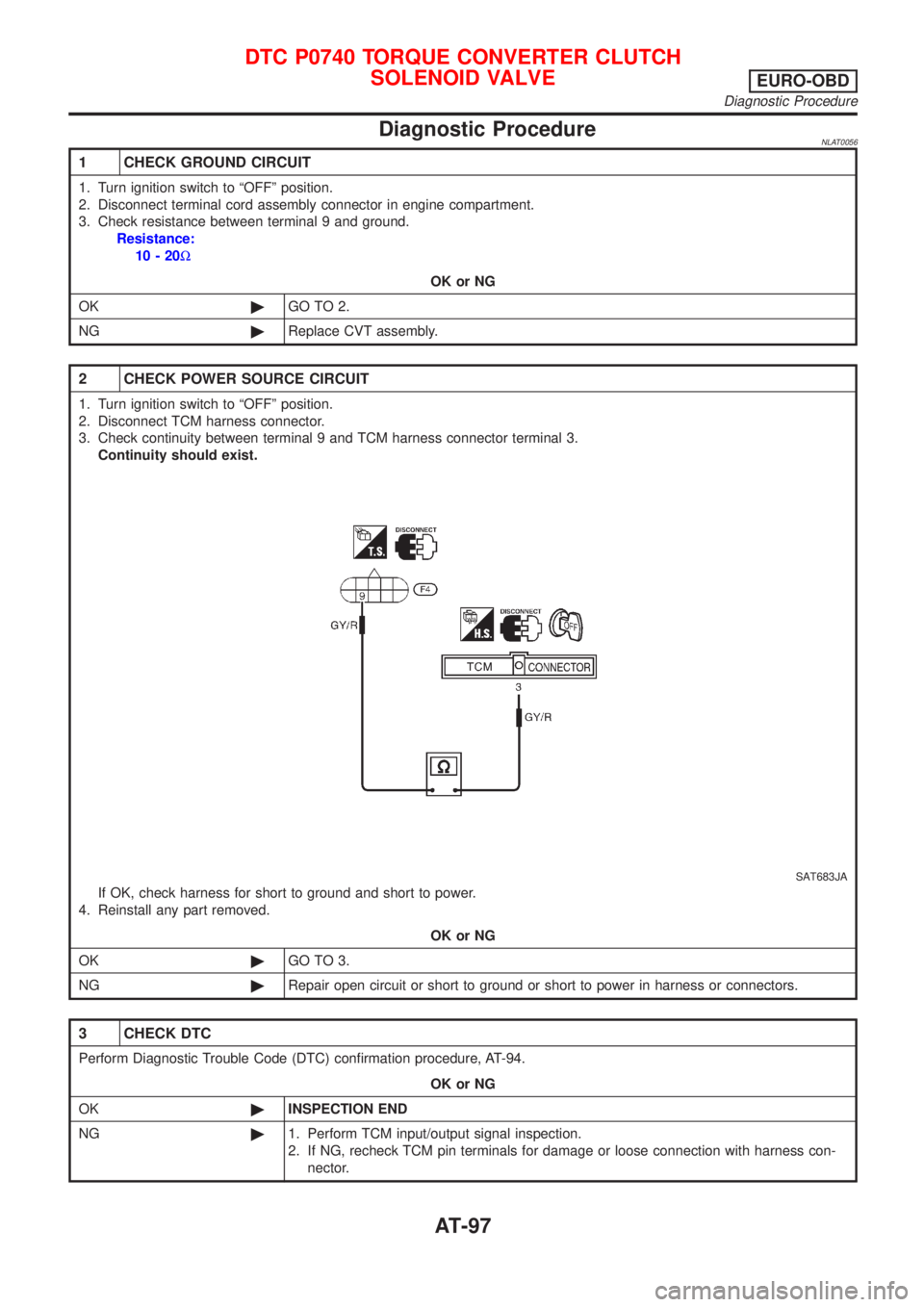
3. Check continuity between terminal 9 and TCM harness connector terminal 3.
Continuity should exist.
SAT683JA
If OK, check harness for short to ground and short to power.
4. Reinstall any part removed.
OK or NG
OK©GO TO 3.
NG©Repair open circuit or short to ground or short to power in harness or connectors.
3 CHECK DTC
Perform Diagnostic Trouble Code (DTC) confirmation procedure, AT-94.
OK or NG
OK©INSPECTION END
NG©1. Perform TCM input/output signal inspection.
2. If NG, recheck TCM pin terminals for damage or loose connection with harness con-
nector.
DTC P0740 TORQUE CONVERTER CLUTCH
SOLENOID VALVE
EURO-OBD
Diagnostic Procedure
AT-97
Page 101 of 3051
SAT250K
DIAGNOSTIC TROUBLE CODE (DTC) CONFIRMATION
PROCEDURE
=NLAT0061S04NOTE:
If ªDIAGNOSTIC TROUBLE CODE CONFIRMATION PROCE-
DUREº has been previously conducted, always turn ignition
switch ªOFFº and wait at least 5 seconds before conducting
the next test.
After the repair, perform the following procedure to confirm the
malfunction is eliminated.
SAT255K
With CONSULT-II
1) Turn ignition switch ªONº and select ªDATA MONITORº mode
for ªENGINEº with CONSULT-II.
2) Depress accelerator pedal completely and wait at least 5 sec-
onds.
If the check result is ªNGº, go to ªDiagnostic Procedureº,
AT-102.
With GST
Follow the procedure ªWith CONSULT-IIº.
DTC P0745 LINE PRESSURE SOLENOID VALVEEURO-OBD
Description (Cont'd)
AT-100
Page 103 of 3051
Diagnostic ProcedureNLAT0062
1 CHECK GROUND CIRCUIT
1. Turn ignition switch to ªOFFº position.
2. Disconnect terminal cord assembly connector in engine compartment.
3. Check resistance between terminal 8 and ground.
Resistance:
2.5-5W
OK or NG
OK©GO TO 2.
NG©Check the following items:
+Line pressure solenoid valve
Refer to ªComponent Inspectionº, AT-103.
+Harness of terminal cord assembly for short or open
2 CHECK POWER SOURCE CIRCUIT
1. Turn ignition switch to ªOFFº position.
2. Disconnect TCM harness connector.
3. Check resistance between terminal 8 and TCM harness connector terminal 2.
Resistance:
11.2 - 12.8W
OK or NG
OK©GO TO 3.
NG©Check the following items:
+Dropping resistor
Refer to ªComponent Inspectionº, AT-103.
+Harness for short or open between TCM terminal 2 and terminal cord assembly (Main
harness)
3 CHECK POWER SOURCE CIRCUIT
1. Turn ignition switch to ªOFFº position.
2. Check continuity between terminal 8 and TCM harness connector terminal 1.
Continuity should exist.
If OK, check harness for short to ground and short to power.
3. Reinstall any part removed.
OK or NG
OK©GO TO 4.
NG©Repair open circuit or short to ground or short to power in harness or connectors.
4 CHECK DTC
Perform Diagnostic Trouble Code (DTC) confirmation procedure, AT-100.
OK or NG
OK©INSPECTION END
NG©1. Perform TCM input/output signal inspection.
2. If NG, recheck TCM pin terminals for damage or loose connection with harness con-
nector.
DTC P0745 LINE PRESSURE SOLENOID VALVEEURO-OBD
Diagnostic Procedure
AT-102
Page 105 of 3051
SAT233K
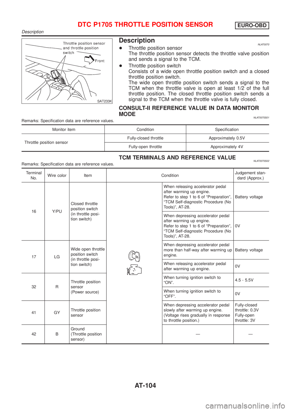
DescriptionNLAT0070+Throttle position sensor
The throttle position sensor detects the throttle valve position
and sends a signal to the TCM.
+Throttle position switch
Consists of a wide open throttle position switch and a closed
throttle position switch.
The wide open throttle position switch sends a signal to the
TCM when the throttle valve is open at least 1/2 of the full
throttle position. The closed throttle position switch sends a
signal to the TCM when the throttle valve is fully closed.
CONSULT-II REFERENCE VALUE IN DATA MONITOR
MODE
NLAT0070S01Remarks: Specification data are reference values.
Monitor item Condition Specification
Throttle position sensorFully-closed throttle Approximately 0.5V
Fully-open throttle Approximately 4V
TCM TERMINALS AND REFERENCE VALUENLAT0070S02Remarks: Specification data are reference values.
Terminal
No.Wire color Item ConditionJudgement stan-
dard (Approx.)
16 Y/PUClosed throttle
position switch
(in throttle posi-
tion switch)
When releasing accelerator pedal
after warming up engine.
Refer to step 1 to 6 of ªPreparationº,
ªTCM Self-diagnostic Procedure (No
Tools)º, AT-28.Battery voltage
When depressing accelerator pedal
after warming up engine.
Refer to step 1 to 6 of ªPreparationº,
ªTCM Self-diagnostic Procedure (No
Tools)º, AT-28.0V
17 LGWide open throttle
position switch
(in throttle posi-
tion switch)When depressing accelerator pedal
more than half-way after warming up
engine.Battery voltage
When releasing accelerator pedal
after warming up engine.0V
32 RThrottle position
sensor
(Power source)When turning ignition switch to
ªONº.4.5 - 5.5V
When turning ignition switch to
ªOFFº.0V
41 GYThrottle position
sensorWhen depressing accelerator pedal
slowly after warming up engine.
(Voltage rises gradually in response
to throttle position.)Fully-closed
throttle: 0.3V
Fully-open
throttle: 3V
42 BGround
(Throttle position
sensor)ÐÐ
DTC P1705 THROTTLE POSITION SENSOREURO-OBD
Description
AT-104