Page 106 of 3051
ON BOARD DIAGNOSIS LOGICNLAT0070S03
Diagnostic trouble code Malfunction is detected when ... Check items (Possible cause)
: TP SEN/CIRC A/T
TCM receives an excessively low or high
voltage from the sensor.+Harness or connectors
(The sensor circuit is open or shorted.)
+Throttle position sensor
+Throttle position switch
: P1705
: MI Code No. 1705
SAT250K
SAT252K
SAT255K
DIAGNOSTIC TROUBLE CODE (DTC) CONFIRMATION
PROCEDURE
NLAT0070S04CAUTION:
Always drive vehicle at a safe speed.
NOTE:
If ªDIAGNOSTIC TROUBLE CODE CONFIRMATION PROCE-
DUREº has been previously conducted, always turn ignition
switch ªOFFº and wait at least 5 seconds before conducting
the next test.
After the repair, perform the following procedure to confirm the
malfunction is eliminated.
With CONSULT-II
1) Turn ignition switch ªONº and select ªDATA MONITORº mode
for ªCVTº with CONSULT-II.
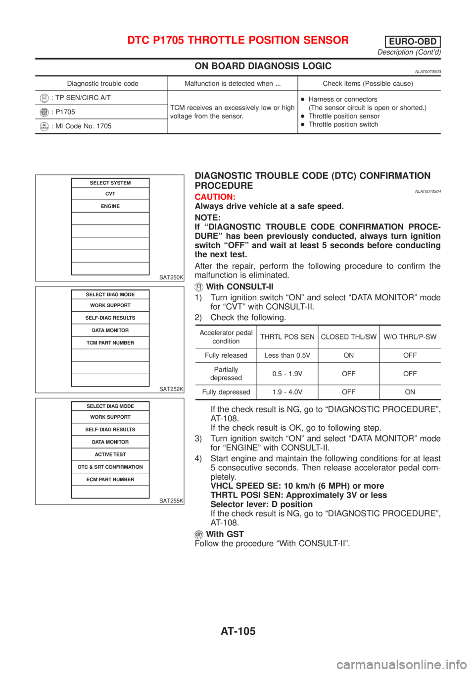
2) Check the following.
Accelerator pedal
conditionTHRTL POS SEN CLOSED THL/SW W/O THRL/P-SW
Fully released Less than 0.5V ON OFF
Partially
depressed0.5 - 1.9V OFF OFF
Fully depressed 1.9 - 4.0V OFF ON
If the check result is NG, go to ªDIAGNOSTIC PROCEDUREº,
AT-108.
If the check result is OK, go to following step.
3) Turn ignition switch ªONº and select ªDATA MONITORº mode
for ªENGINEº with CONSULT-II.
4) Start engine and maintain the following conditions for at least
5 consecutive seconds. Then release accelerator pedal com-
pletely.
VHCL SPEED SE: 10 km/h (6 MPH) or more
THRTL POSI SEN: Approximately 3V or less
Selector lever: D position
If the check result is NG, go to ªDIAGNOSTIC PROCEDUREº,
AT-108.
With GST
Follow the procedure ªWith CONSULT-IIº.
DTC P1705 THROTTLE POSITION SENSOREURO-OBD
Description (Cont'd)
AT-105
Page 109 of 3051
Diagnostic ProcedureNLAT0071
1 CHECK DTC WITH ECM
Perform diagnostic test mode II (self-diagnostic results) for engine control.
Refer to EC section [ªMalfunction Indicator (MI)º, ªON BOARD DIAGNOSTIC SYSTEM DESCRIPTIONº].
OK or NG
OK (With CONSULT-II)©GO TO 2.
OK (Without CONSULT-
II)©GO TO 3.
NG©Check throttle position sensor circuit for engine control. Refer to EC section (ªDTC
P0120 THROTTLE POSITION SENSORº).
2 CHECK INPUT SIGNAL (With CONSULT-II)
With CONSULT-II
1. Turn ignition switch to ªONº position.
(Do not start engine.)
2. Select ªTCM INPUT SIGNALSº in ªDATA MONITORº mode for ªCVTº with CONSULT-II.
3. Read out the value of ªTHRTL POS SENº.
Voltage:
Fully-closed throttle:
Approximately 0.5V
Fully-open throttle:
Approximately 4V
OK or NG
OK©GO TO 4.
NG©Check harness for short or open between ECM and TCM regarding throttle position sen-
sor circuit. (Main harness)
3 CHECK INPUT SIGNAL (Without CONSULT-II)
Without CONSULT-II
1. Turn ignition switch to ªONº position.
(Do not start engine.)
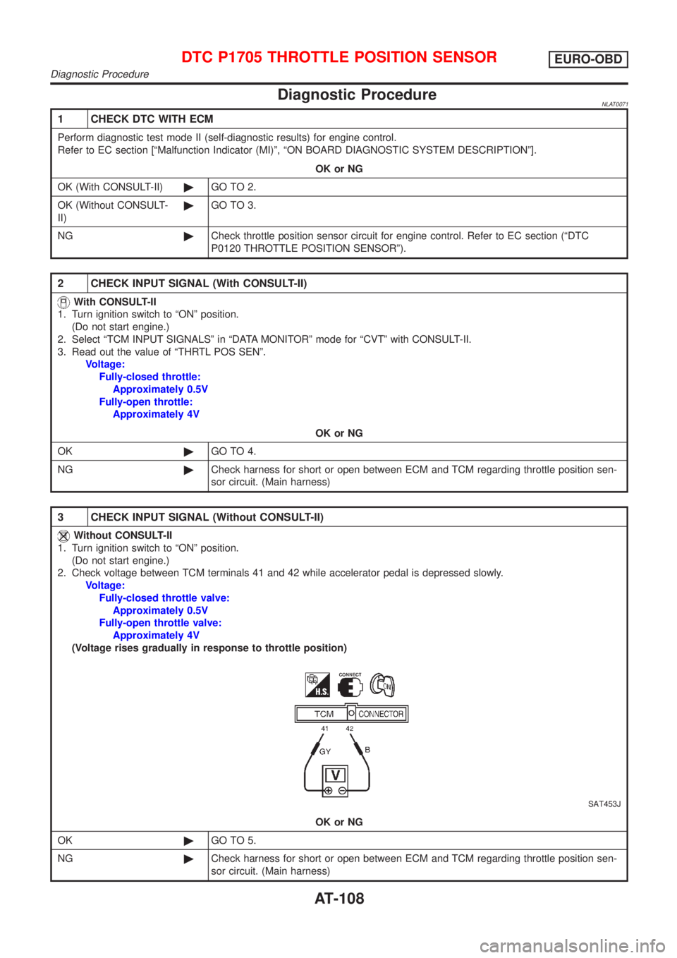
2. Check voltage between TCM terminals 41 and 42 while accelerator pedal is depressed slowly.
Voltage:
Fully-closed throttle valve:
Approximately 0.5V
Fully-open throttle valve:
Approximately 4V
(Voltage rises gradually in response to throttle position)
SAT453J
OK or NG
OK©GO TO 5.
NG©Check harness for short or open between ECM and TCM regarding throttle position sen-
sor circuit. (Main harness)
DTC P1705 THROTTLE POSITION SENSOREURO-OBD
Diagnostic Procedure
AT-108
Page 110 of 3051
4 CHECK THROTTLE POSITION SWITCH CIRCUIT (With CONSULT-II)
With CONSULT-II
1. Refer to steps 1 to 7 of ªPreparationº, ªTCM Self-diagnostic Procedure (No Tools)º, AT-28.
2. Turn ignition switch to ªOFFº position.
3. Turn ignition switch to ªONº position.
(Do not start engine.)
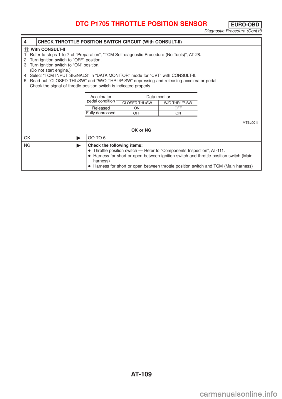
4. Select ªTCM INPUT SIGNALSº in ªDATA MONITORº mode for ªCVTº with CONSULT-II.
5. Read out ªCLOSED THL/SWº and ªW/O THRL/P-SWº depressing and releasing accelerator pedal.
Check the signal of throttle position switch is indicated properly.
MTBL0011
OK or NG
OK©GO TO 6.
NG©Check the following items:
+Throttle position switch Ð Refer to ªComponents Inspectionº, AT-111.
+Harness for short or open between ignition switch and throttle position switch (Main
harness)
+Harness for short or open between throttle position switch and TCM (Main harness)
DTC P1705 THROTTLE POSITION SENSOREURO-OBD
Diagnostic Procedure (Cont'd)
AT-109
Page 111 of 3051
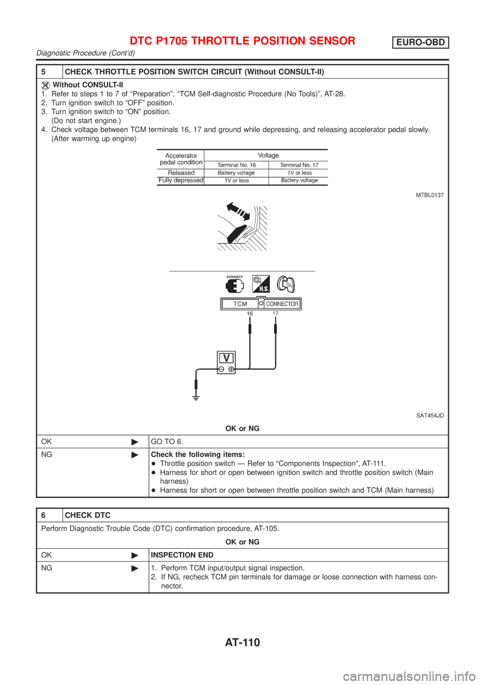
5 CHECK THROTTLE POSITION SWITCH CIRCUIT (Without CONSULT-II)
Without CONSULT-II
1. Refer to steps 1 to 7 of ªPreparationº, ªTCM Self-diagnostic Procedure (No Tools)º, AT-28.
2. Turn ignition switch to ªOFFº position.
3. Turn ignition switch to ªONº position.
(Do not start engine.)
4. Check voltage between TCM terminals 16, 17 and ground while depressing, and releasing accelerator pedal slowly.
(After warming up engine)
MTBL0137
SAT454JD
OK or NG
OK©GO TO 6.
NG©Check the following items:
+Throttle position switch Ð Refer to ªComponents Inspectionº, AT-111.
+Harness for short or open between ignition switch and throttle position switch (Main
harness)
+Harness for short or open between throttle position switch and TCM (Main harness)
6 CHECK DTC
Perform Diagnostic Trouble Code (DTC) confirmation procedure, AT-105.
OK or NG
OK©INSPECTION END
NG©1. Perform TCM input/output signal inspection.
2. If NG, recheck TCM pin terminals for damage or loose connection with harness con-
nector.
DTC P1705 THROTTLE POSITION SENSOREURO-OBD
Diagnostic Procedure (Cont'd)
AT-110
Page 114 of 3051
SAT250K
SAT255K
DIAGNOSTIC TROUBLE CODE (DTC) CONFIRMATION
PROCEDURE
NLAT0224S04CAUTION:
+Always drive vehicle at a safe speed.
+Be careful not to rev engine into the red zone on the
tachometer.
NOTE:
If ªDIAGNOSTIC TROUBLE CODE CONFIRMATION PROCE-
DUREº has been previously conducted, always turn ignition
switch ªOFFº and wait at least 5 seconds before conducting
the next test.
After the repair, perform the following procedure to confirm the
malfunction is eliminated.
With CONSULT-II
1) Turn ignition switch ªONº and select ªDATA MONITORº mode
for ªCVTº with CONSULT-II.
2) Drive vehicle for at least 5 consecutive seconds.
If the check result is ªNGº, go to ªDiagnostic Procedureº,
AT-115.
With GST
Follow the procedure ªWith CONSULT-IIº.
DTC P1777 STEP MOTOR Ð CIRCUITEURO-OBD
Description (Cont'd)
AT-113
Page 116 of 3051
Diagnostic ProcedureNLAT0226
1 CHECK POWER SOURCE CIRCUIT
1. Turn ignition switch to ªONº position.
2. Check ªSELF-DIAG RESULTSº with CONSULT-II.
3. If ªCVT SAFE FUNCTIONº activate, refer to ªCVT SAFE FUNCTIONº, AT-125.
4. Turn ignition switch to ªOFFº position.
5. Disconnect TCM harness connector.
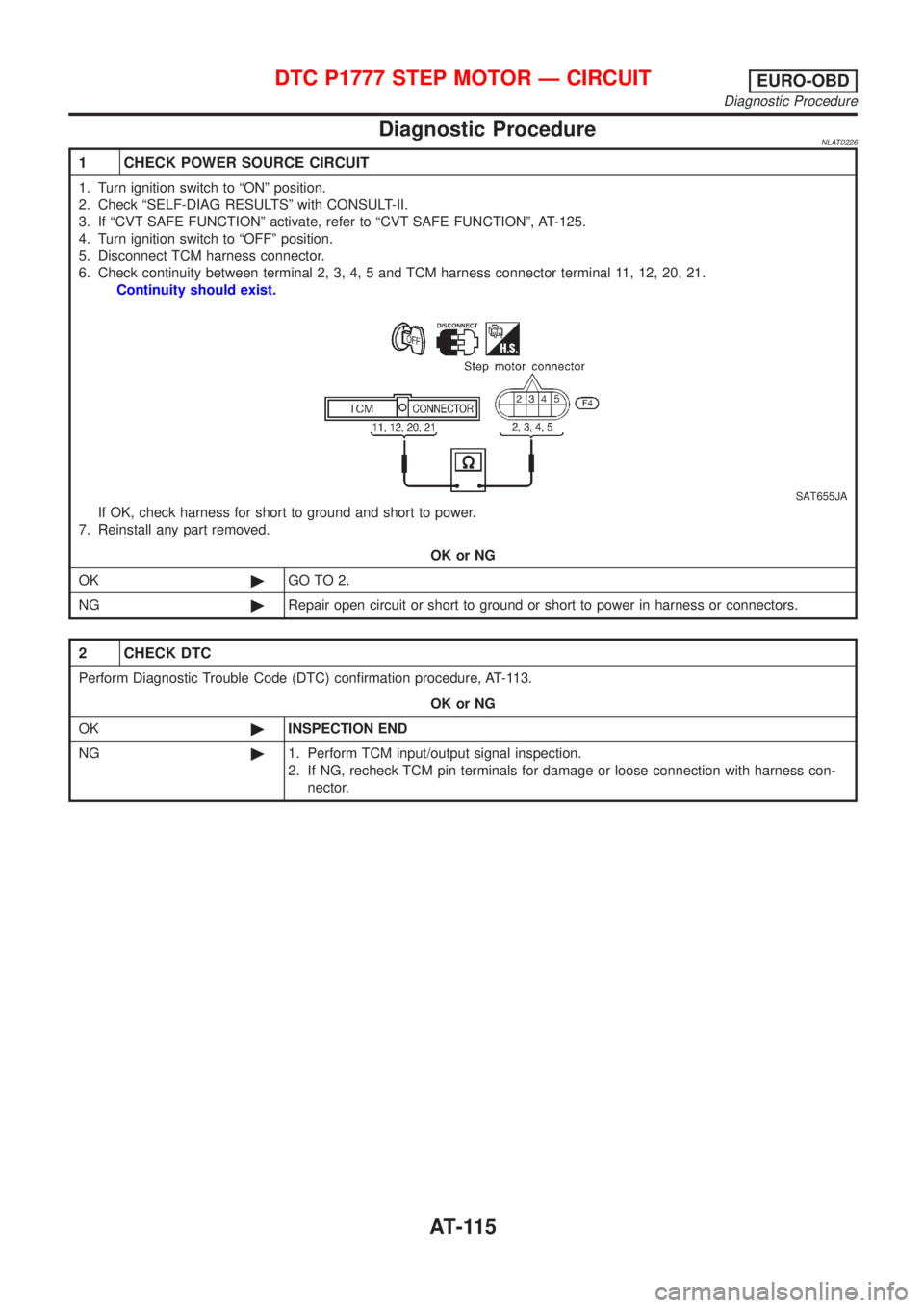
6. Check continuity between terminal 2, 3, 4, 5 and TCM harness connector terminal 11, 12, 20, 21.
Continuity should exist.
SAT655JA
If OK, check harness for short to ground and short to power.
7. Reinstall any part removed.
OK or NG
OK©GO TO 2.
NG©Repair open circuit or short to ground or short to power in harness or connectors.
2 CHECK DTC
Perform Diagnostic Trouble Code (DTC) confirmation procedure, AT-113.
OK or NG
OK©INSPECTION END
NG©1. Perform TCM input/output signal inspection.
2. If NG, recheck TCM pin terminals for damage or loose connection with harness con-
nector.
DTC P1777 STEP MOTOR Ð CIRCUITEURO-OBD
Diagnostic Procedure
AT-115
Page 119 of 3051

SAT250K
SAT252K
SAT255K
DIAGNOSTIC TROUBLE CODE (DTC) CONFIRMATION
PROCEDURE
NLAT0228S04CAUTION:
+Always drive vehicle at a safe speed.
+Be careful not to rev engine into the red zone on the
tachometer.
+Before start ªDIAGNOSTIC TROUBLE CODE (DTC) CON-
FIRMATION PROCEDUREº, confirm ªHiº or ªMidº or
ªLowº fixation by ªI/P PULLY SPDº and ªVHCL SPEED SEº
on ªDATA MONITOR MODEº.
+If hi-geared fixation, go to diagnostic procedure soon.
NOTE:
If ªDIAGNOSTIC TROUBLE CODE CONFIRMATION PROCE-
DUREº has been previously conducted, always turn ignition
switch ªOFFº and wait at least 5 seconds before conducting
the next test.
After the repair, perform the following procedure to confirm the
malfunction is eliminated.
With CONSULT-II
1) Turn ignition switch ªONº and select ªDATA MONITORº mode
for ªCVTº with CONSULT-II.
2) Make sure that output voltage of CVT fluid temperature sen-
sor is within the range below.
FLUID TEMP SEN: 0.5 - 1.5V
If out of range, drive the vehicle to decrease the voltage
(warm up the fluid) or stop engine to increase the voltage
(cool down the fluid)
3) Select ªENGINEº mode for ªENGINEº with CONSULT-II.
4) Start engine and maintain the following conditions for at least
30 consecutive seconds.
TEST START FROM 0 km/h (0 MPH)
CONSTANT ACCELERATION: Keep 30 sec or more
VHCL SPEED SE: 10 km/h (6 MPH) or more
THRTL POS SEN: More than 1.3V
Selector lever: D position
ENG SPEED: 450 rpm or more
If the check result is NG, go to ªDIAGNOSTIC PROCEDUREº,
AT-118.
With GST
Follow the procedure ªWith CONSULT-IIº.
Diagnostic ProcedureNLAT0230
1 CHECK STEP MOTOR
+It is monitoring whether ªCVT ratio: 2.32 - 0.47º changes similarly to ªPLY CONT STEP: -3 - 200º by DATA MONITOR
mode.
+If no CONSULT-II, inspect the engine speed (rise and descend) about vehicle speed and throttle opening angle, and
check shift change.
OK or NG
OK©INSPECTION END
NG©Replace CVT assembly.
DTC P1778 STEP MOTOR Ð FUNCTIONEURO-OBD
Description (Cont'd)
AT-118
Page 121 of 3051
SAT250K
SAT252K
SAT255K
DIAGNOSTIC TROUBLE CODE (DTC) CONFIRMATION
PROCEDURE
NLAT0232S04CAUTION:
+Always drive vehicle at a safe speed.
+Be careful not to rev engine into the red zone on the
tachometer.
NOTE:
If ªDIAGNOSTIC TROUBLE CODE CONFIRMATION PROCE-
DUREº has been previously conducted, always turn ignition
switch ªOFFº and wait at least 5 seconds before conducting
the next test.
After the repair, perform the following procedure to confirm the
malfunction is eliminated.
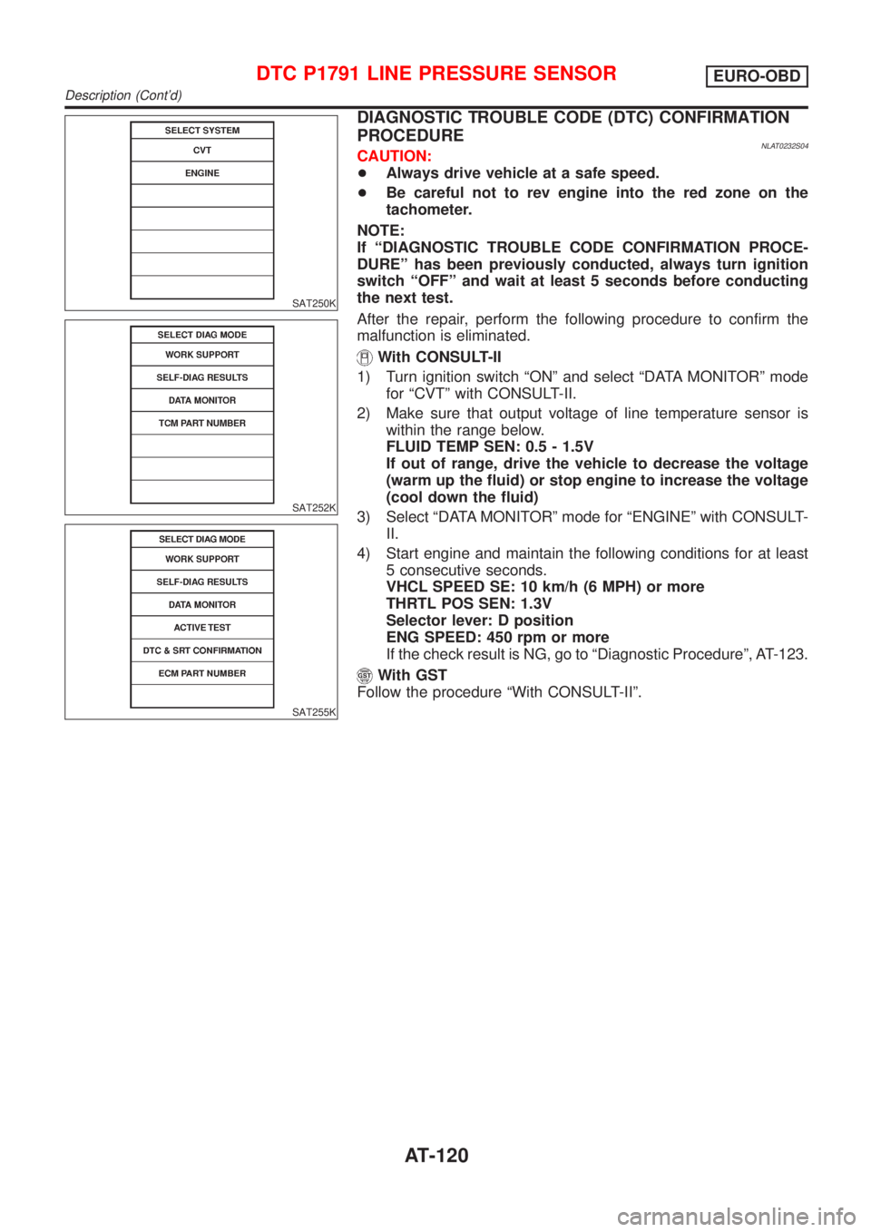
With CONSULT-II
1) Turn ignition switch ªONº and select ªDATA MONITORº mode
for ªCVTº with CONSULT-II.
2) Make sure that output voltage of line temperature sensor is
within the range below.
FLUID TEMP SEN: 0.5 - 1.5V
If out of range, drive the vehicle to decrease the voltage
(warm up the fluid) or stop engine to increase the voltage
(cool down the fluid)
3) Select ªDATA MONITORº mode for ªENGINEº with CONSULT-
II.
4) Start engine and maintain the following conditions for at least
5 consecutive seconds.
VHCL SPEED SE: 10 km/h (6 MPH) or more
THRTL POS SEN: 1.3V
Selector lever: D position
ENG SPEED: 450 rpm or more
If the check result is NG, go to ªDiagnostic Procedureº, AT-123.
With GST
Follow the procedure ªWith CONSULT-IIº.
DTC P1791 LINE PRESSURE SENSOREURO-OBD
Description (Cont'd)
AT-120