Page 1204 of 3051

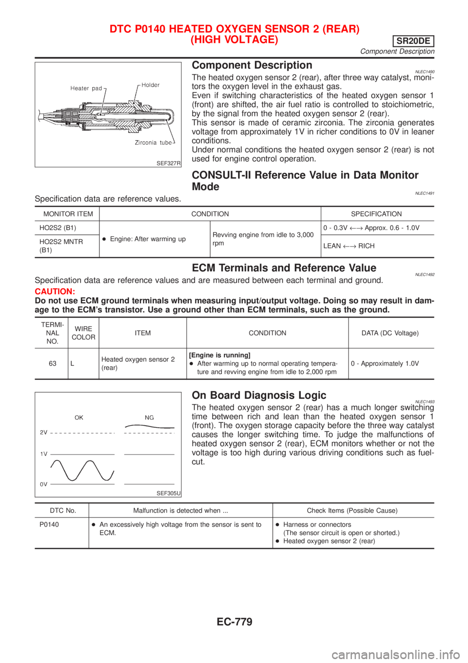
SEF327R
Component DescriptionNLEC1490The heated oxygen sensor 2 (rear), after three way catalyst, moni-
tors the oxygen level in the exhaust gas.
Even if switching characteristics of the heated oxygen sensor 1
(front) are shifted, the air fuel ratio is controlled to stoichiometric,
by the signal from the heated oxygen sensor 2 (rear).
This sensor is made of ceramic zirconia. The zirconia generates
voltage from approximately 1V in richer conditions to 0V in leaner
conditions.
Under normal conditions the heated oxygen sensor 2 (rear) is not
used for engine control operation.
CONSULT-II Reference Value in Data Monitor
Mode
NLEC1491Specification data are reference values.
MONITOR ITEM CONDITION SPECIFICATION
HO2S2 (B1)
+Engine: After warming upRevving engine from idle to 3,000
rpm0 - 0.3V¨Approx. 0.6 - 1.0V
HO2S2 MNTR
(B1)LEAN¨RICH
ECM Terminals and Reference ValueNLEC1492Specification data are reference values and are measured between each terminal and ground.
CAUTION:
Do not use ECM ground terminals when measuring input/output voltage. Doing so may result in dam-
age to the ECM's transistor. Use a ground other than ECM terminals, such as the ground.
TERMI-
NAL
NO.WIRE
COLORITEM CONDITION DATA (DC Voltage)
63 LHeated oxygen sensor 2
(rear)[Engine is running]
+After warming up to normal operating tempera-
ture and revving engine from idle to 2,000 rpm0 - Approximately 1.0V
SEF305U
On Board Diagnosis LogicNLEC1493The heated oxygen sensor 2 (rear) has a much longer switching
time between rich and lean than the heated oxygen sensor 1
(front). The oxygen storage capacity before the three way catalyst
causes the longer switching time. To judge the malfunctions of
heated oxygen sensor 2 (rear), ECM monitors whether or not the
voltage is too high during various driving conditions such as fuel-
cut.
DTC No. Malfunction is detected when ... Check Items (Possible Cause)
P0140+An excessively high voltage from the sensor is sent to
ECM.+Harness or connectors
(The sensor circuit is open or shorted.)
+Heated oxygen sensor 2 (rear)
DTC P0140 HEATED OXYGEN SENSOR 2 (REAR)
(HIGH VOLTAGE)
SR20DE
Component Description
EC-779
Page 1250 of 3051

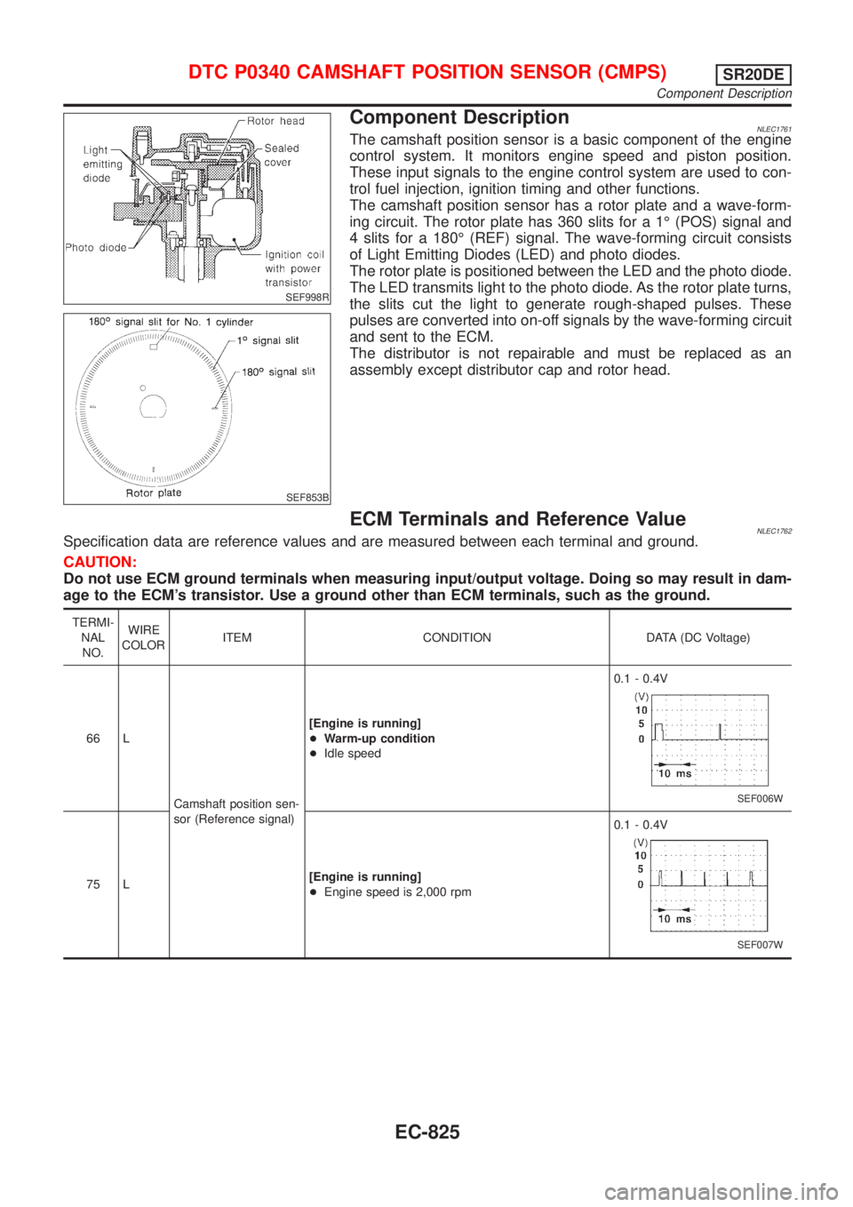
SEF998R
SEF853B
Component DescriptionNLEC1761The camshaft position sensor is a basic component of the engine
control system. It monitors engine speed and piston position.
These input signals to the engine control system are used to con-
trol fuel injection, ignition timing and other functions.
The camshaft position sensor has a rotor plate and a wave-form-
ing circuit. The rotor plate has 360 slits for a 1É (POS) signal and
4 slits for a 180É (REF) signal. The wave-forming circuit consists
of Light Emitting Diodes (LED) and photo diodes.
The rotor plate is positioned between the LED and the photo diode.
The LED transmits light to the photo diode. As the rotor plate turns,
the slits cut the light to generate rough-shaped pulses. These
pulses are converted into on-off signals by the wave-forming circuit
and sent to the ECM.
The distributor is not repairable and must be replaced as an
assembly except distributor cap and rotor head.
ECM Terminals and Reference ValueNLEC1762Specification data are reference values and are measured between each terminal and ground.
CAUTION:
Do not use ECM ground terminals when measuring input/output voltage. Doing so may result in dam-
age to the ECM's transistor. Use a ground other than ECM terminals, such as the ground.
TERMI-
NAL
NO.WIRE
COLORITEM CONDITION DATA (DC Voltage)
66 L
Camshaft position sen-
sor (Reference signal)[Engine is running]
+Warm-up condition
+Idle speed0.1 - 0.4V
SEF006W
75 L[Engine is running]
+Engine speed is 2,000 rpm0.1 - 0.4V
SEF007W
DTC P0340 CAMSHAFT POSITION SENSOR (CMPS)SR20DE
Component Description
EC-825
Page 1508 of 3051
Injection Tube and Injection Nozzle
REMOVAL AND INSTALLATIONNLEC0618CAUTION:
+Do not disassemble injection nozzle assembly. If NG,
replace injection nozzle assembly.
+Plug flare nut with a cap or rag so that no dust enters the
nozzle. Cover nozzle tip to protect it.
JEF443Z
JEF340Y
Injection TubeNLEC0618S01RemovalNLEC0618S01011. Mark the cylinder Nos. to the injection tubes, then disconnect
them.
+Marking should be made at proper locations and by the
proper method, so that they are not erased by fuel, etc.
2. Remove the clamps, then disconnect the tubes one by one.
+The intake manifold is removed for explanation in the figure.
BASIC SERVICE PROCEDUREYD22DDTI
Injection Tube and Injection Nozzle
EC-1083
Page 2480 of 3051

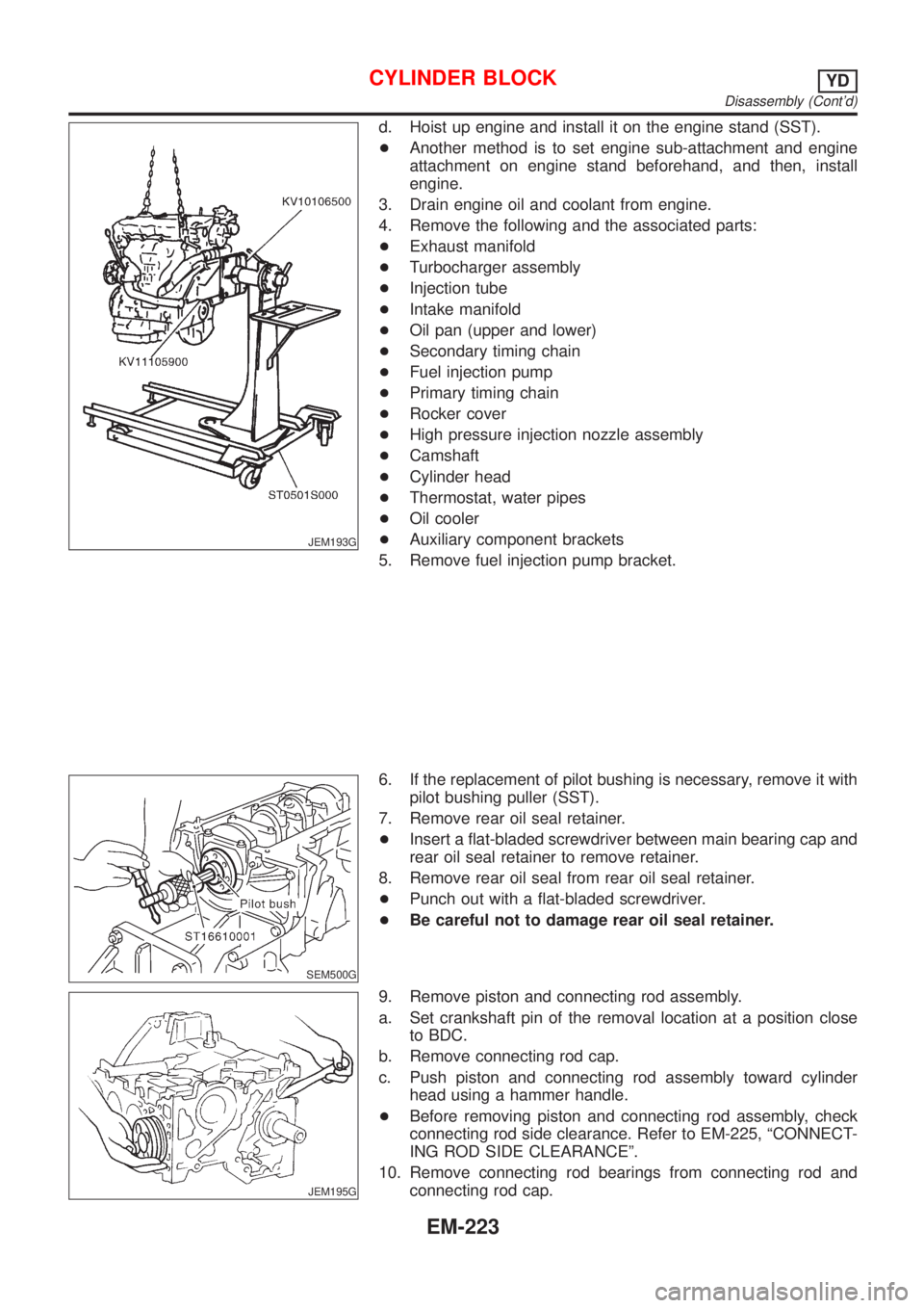
JEM193G
d. Hoist up engine and install it on the engine stand (SST).
+Another method is to set engine sub-attachment and engine
attachment on engine stand beforehand, and then, install
engine.
3. Drain engine oil and coolant from engine.
4. Remove the following and the associated parts:
+Exhaust manifold
+Turbocharger assembly
+Injection tube
+Intake manifold
+Oil pan (upper and lower)
+Secondary timing chain
+Fuel injection pump
+Primary timing chain
+Rocker cover
+High pressure injection nozzle assembly
+Camshaft
+Cylinder head
+Thermostat, water pipes
+Oil cooler
+Auxiliary component brackets
5. Remove fuel injection pump bracket.
SEM500G
6. If the replacement of pilot bushing is necessary, remove it with
pilot bushing puller (SST).
7. Remove rear oil seal retainer.
+Insert a flat-bladed screwdriver between main bearing cap and
rear oil seal retainer to remove retainer.
8. Remove rear oil seal from rear oil seal retainer.
+Punch out with a flat-bladed screwdriver.
+Be careful not to damage rear oil seal retainer.
JEM195G
9. Remove piston and connecting rod assembly.
a. Set crankshaft pin of the removal location at a position close
to BDC.
b. Remove connecting rod cap.
c. Push piston and connecting rod assembly toward cylinder
head using a hammer handle.
+Before removing piston and connecting rod assembly, check
connecting rod side clearance. Refer to EM-225, ªCONNECT-
ING ROD SIDE CLEARANCEº.
10. Remove connecting rod bearings from connecting rod and
connecting rod cap.
CYLINDER BLOCKYD
Disassembly (Cont'd)
EM-223
Page 2515 of 3051
Fuel TankNLFE0006
YFE005
JFE613A
REMOVALNLFE0006S011. Disconnect battery ground cable.
2. Open fuel filler lid and filler cap.
3. Drain fuel from fuel tank.
4. Remove rear seat cushion. Refer to BT-49,“Removal and
Installation”.
5. Remove inspection hole cover under the rear seat.
FUEL SYSTEMQG/SR
Fuel Tank
FE-6
Page 2516 of 3051
SFE639A
SFE640A
6. Disconnect electrical connector.
7. Disconnect the quick connector as follows.
a. Put mating marks on tubes and connectors for correct instal-
lation.
SFE562A
b. Hold the connector while pushing in tabs, and pull out the tube.
CAUTION:
+The tube can be removed when the tabs are completely
depressed. Do not twist it more than necessary.
+Do not use any tools to remove the quick connector.
+Keep the resin tube away from heat. Be especially careful
when welding near the tube.
+Prevent acid liquid such as battery electrolyte etc. from
getting on the resin tube.
+Do not bend or twist the tube during installation and
removal.
SFE650A
8. From rear left area of fuel tank, remove filler hose, vent hose,
and EVAP hose.
CAUTION:
To prevent fuel from flowing out, install a blind cap immedi-
ately after the fuel hose is disconnected.
SFE642A
9. Remove exhaust center tube.
FUEL SYSTEMQG/SR
Fuel Tank (Cont’d)
FE-7
Page 2518 of 3051
Fuel Pump, Fuel Level Sensor Unit and Fuel
Filter
NLFE0007
NFE065
JFE613A
REMOVALNLFE0007S011. Disconnect battery ground cable.
2. Open fuel filler lid and filler cap.
3. Remove rear seat cushion. Refer to BT-49,“Removal and
Installation”.
4. Remove inspection hole cover under the rear seat.
SFE639A
5. Disconnect electrical connector.
6. Disconnect the quick connectors.
+For disconnect of quick connectors, refer to step 7. of“Fuel
Tank Removal”.
FUEL SYSTEMQG/SR
Fuel Pump, Fuel Level Sensor Unit and Fuel Filter
FE-9
Page 2528 of 3051

JFE613A
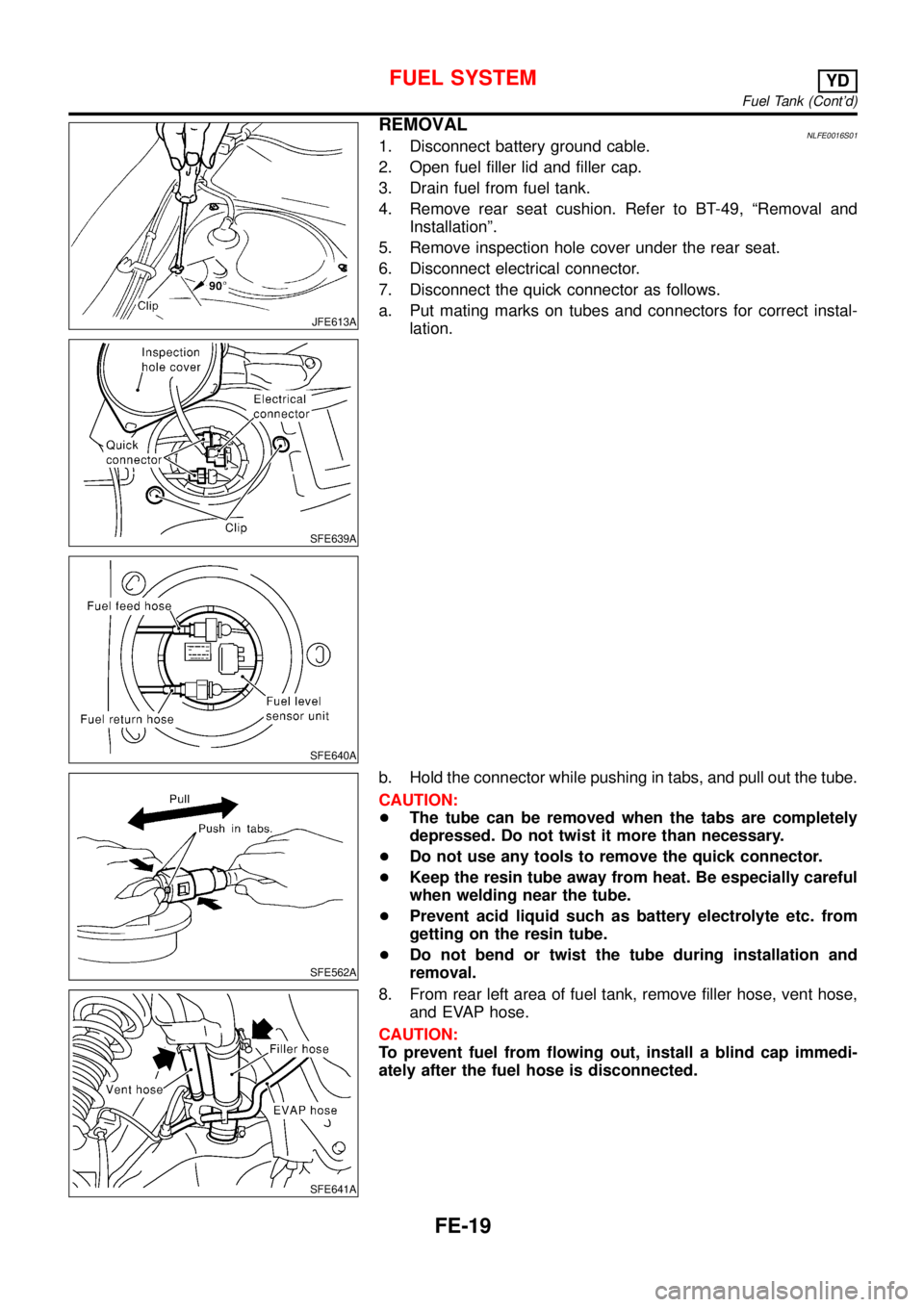
SFE639A
SFE640A
REMOVALNLFE0016S011. Disconnect battery ground cable.
2. Open fuel filler lid and filler cap.
3. Drain fuel from fuel tank.
4. Remove rear seat cushion. Refer to BT-49,“Removal and
Installation”.
5. Remove inspection hole cover under the rear seat.
6. Disconnect electrical connector.
7. Disconnect the quick connector as follows.
a. Put mating marks on tubes and connectors for correct instal-
lation.
SFE562A
b. Hold the connector while pushing in tabs, and pull out the tube.
CAUTION:
+The tube can be removed when the tabs are completely
depressed. Do not twist it more than necessary.
+Do not use any tools to remove the quick connector.
+Keep the resin tube away from heat. Be especially careful
when welding near the tube.
+Prevent acid liquid such as battery electrolyte etc. from
getting on the resin tube.
+Do not bend or twist the tube during installation and
removal.
SFE641A
8. From rear left area of fuel tank, remove filler hose, vent hose,
and EVAP hose.
CAUTION:
To prevent fuel from flowing out, install a blind cap immedi-
ately after the fuel hose is disconnected.
FUEL SYSTEMYD
Fuel Tank (Cont’d)
FE-19