2001 NISSAN ALMERA TINO fuel cap
[x] Cancel search: fuel capPage 681 of 3051
SEF327R
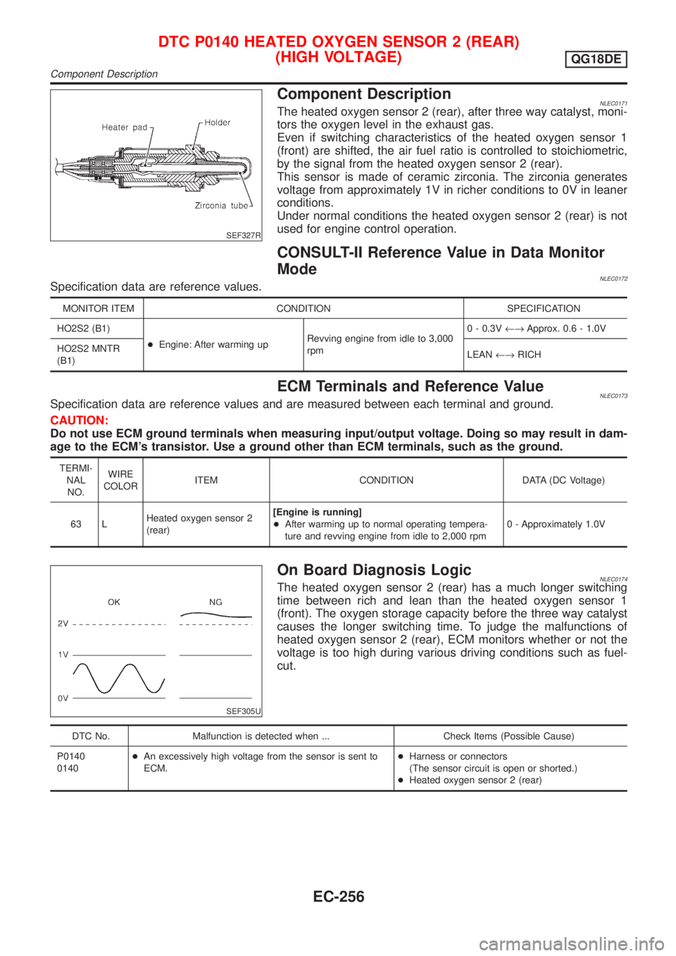
Component DescriptionNLEC0171The heated oxygen sensor 2 (rear), after three way catalyst, moni-
tors the oxygen level in the exhaust gas.
Even if switching characteristics of the heated oxygen sensor 1
(front) are shifted, the air fuel ratio is controlled to stoichiometric,
by the signal from the heated oxygen sensor 2 (rear).
This sensor is made of ceramic zirconia. The zirconia generates
voltage from approximately 1V in richer conditions to 0V in leaner
conditions.
Under normal conditions the heated oxygen sensor 2 (rear) is not
used for engine control operation.
CONSULT-II Reference Value in Data Monitor
Mode
NLEC0172Specification data are reference values.
MONITOR ITEM CONDITION SPECIFICATION
HO2S2 (B1)
+Engine: After warming upRevving engine from idle to 3,000
rpm0 - 0.3V¨Approx. 0.6 - 1.0V
HO2S2 MNTR
(B1)LEAN¨RICH
ECM Terminals and Reference ValueNLEC0173Specification data are reference values and are measured between each terminal and ground.
CAUTION:
Do not use ECM ground terminals when measuring input/output voltage. Doing so may result in dam-
age to the ECM's transistor. Use a ground other than ECM terminals, such as the ground.
TERMI-
NAL
NO.WIRE
COLORITEM CONDITION DATA (DC Voltage)
63 LHeated oxygen sensor 2
(rear)[Engine is running]
+After warming up to normal operating tempera-
ture and revving engine from idle to 2,000 rpm0 - Approximately 1.0V
SEF305U
On Board Diagnosis LogicNLEC0174The heated oxygen sensor 2 (rear) has a much longer switching
time between rich and lean than the heated oxygen sensor 1
(front). The oxygen storage capacity before the three way catalyst
causes the longer switching time. To judge the malfunctions of
heated oxygen sensor 2 (rear), ECM monitors whether or not the
voltage is too high during various driving conditions such as fuel-
cut.
DTC No. Malfunction is detected when ... Check Items (Possible Cause)
P0140
0140+An excessively high voltage from the sensor is sent to
ECM.+Harness or connectors
(The sensor circuit is open or shorted.)
+Heated oxygen sensor 2 (rear)
DTC P0140 HEATED OXYGEN SENSOR 2 (REAR)
(HIGH VOLTAGE)
QG18DE
Component Description
EC-256
Page 984 of 3051
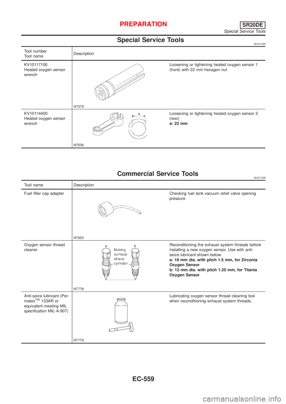
Special Service ToolsNLEC1335
Tool number
Tool nameDescription
KV10117100
Heated oxygen sensor
wrench
NT379
Loosening or tightening heated oxygen sensor 1
(front) with 22 mm hexagon nut
KV10114400
Heated oxygen sensor
wrench
NT636
Loosening or tightening heated oxygen sensor 2
(rear)
a: 22 mm
Commercial Service ToolsNLEC1336
Tool name Description
Fuel filler cap adapter
NT653
Checking fuel tank vacuum relief valve opening
pressure
Oxygen sensor thread
cleaner
NT778
Reconditioning the exhaust system threads before
installing a new oxygen sensor. Use with anti-
seize lubricant shown below.
a: 18 mm dia. with pitch 1.5 mm, for Zirconia
Oxygen Sensor
b: 12 mm dia. with pitch 1.25 mm, for Titania
Oxygen Sensor
Anti-seize lubricant (Per-
matex
TM133AR or
equivalent meeting MIL
specification MIL-A-907)
NT779
Lubricating oxygen sensor thread cleaning tool
when reconditioning exhaust system threads.
PREPARATIONSR20DE
Special Service Tools
EC-559
Page 999 of 3051
rate of vapor controlled by EVAP canister purge volume control solenoid valve is proportionally regulated as
the air flow increases.
EVAP canister purge volume control solenoid valve also shuts off the vapor purge line during decelerating and
idling.
SEF917W
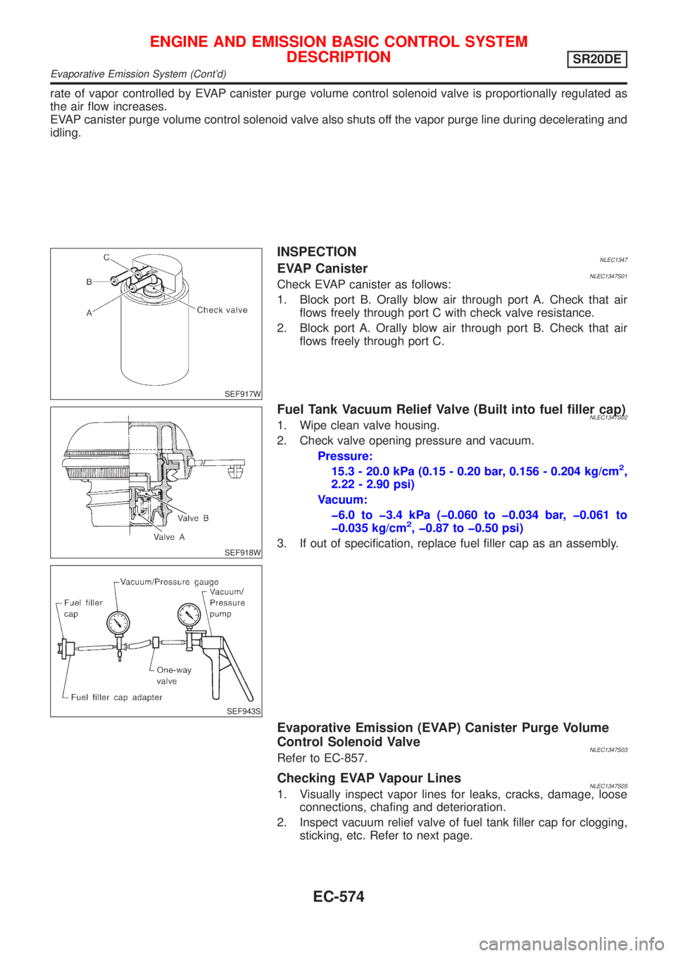
INSPECTIONNLEC1347EVAP CanisterNLEC1347S01Check EVAP canister as follows:
1. Block port B. Orally blow air through port A. Check that air
flows freely through port C with check valve resistance.
2. Block port A. Orally blow air through port B. Check that air
flows freely through port C.
SEF918W
SEF943S
Fuel Tank Vacuum Relief Valve (Built into fuel filler cap)NLEC1347S021. Wipe clean valve housing.
2. Check valve opening pressure and vacuum.
Pressure:
15.3 - 20.0 kPa (0.15 - 0.20 bar, 0.156 - 0.204 kg/cm
2,
2.22 - 2.90 psi)
Vacuum:
þ6.0 to þ3.4 kPa (þ0.060 to þ0.034 bar, þ0.061 to
þ0.035 kg/cm
2, þ0.87 to þ0.50 psi)
3. If out of specification, replace fuel filler cap as an assembly.
Evaporative Emission (EVAP) Canister Purge Volume
Control Solenoid Valve
NLEC1347S03Refer to EC-857.
Checking EVAP Vapour LinesNLEC1347S051. Visually inspect vapor lines for leaks, cracks, damage, loose
connections, chafing and deterioration.
2. Inspect vacuum relief valve of fuel tank filler cap for clogging,
sticking, etc. Refer to next page.
ENGINE AND EMISSION BASIC CONTROL SYSTEM
DESCRIPTION
SR20DE
Evaporative Emission System (Cont'd)
EC-574
Page 1003 of 3051
If results are unsatisfactory, perform Fuel Pressure Regulator
Check, EC-578.
SEF718B
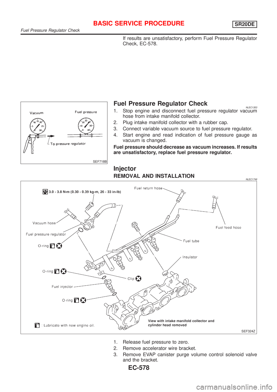
Fuel Pressure Regulator CheckNLEC13531. Stop engine and disconnect fuel pressure regulator vacuum
hose from intake manifold collector.
2. Plug intake manifold collector with a rubber cap.
3. Connect variable vacuum source to fuel pressure regulator.
4. Start engine and read indication of fuel pressure gauge as
vacuum is changed.
Fuel pressure should decrease as vacuum increases. If results
are unsatisfactory, replace fuel pressure regulator.
Injector
REMOVAL AND INSTALLATIONNLEC1746
SEF324Z
1. Release fuel pressure to zero.
2. Remove accelerator wire bracket.
3. Remove EVAP canister purge volume control solenoid valve
and the bracket.
BASIC SERVICE PROCEDURESR20DE
Fuel Pressure Regulator Check
EC-578
Page 1076 of 3051
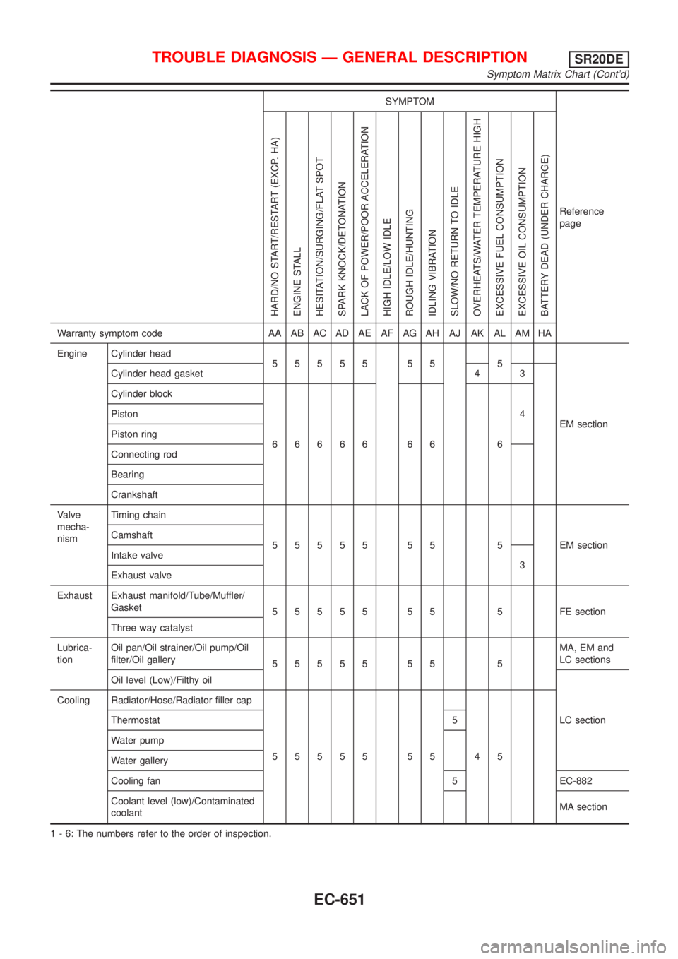
SYMPTOM
Reference
page
HARD/NO START/RESTART (EXCP. HA)
ENGINE STALL
HESITATION/SURGING/FLAT SPOT
SPARK KNOCK/DETONATION
LACK OF POWER/POOR ACCELERATION
HIGH IDLE/LOW IDLE
ROUGH IDLE/HUNTING
IDLING VIBRATION
SLOW/NO RETURN TO IDLE
OVERHEATS/WATER TEMPERATURE HIGH
EXCESSIVE FUEL CONSUMPTION
EXCESSIVE OIL CONSUMPTION
BATTERY DEAD (UNDER CHARGE)
Warranty symptom code AA AB AC AD AE AF AG AH AJ AK AL AM HA
Engine Cylinder head
55555 55 5
EM section Cylinder head gasket 4 3
Cylinder block
66666 66 64 Piston
Piston ring
Connecting rod
Bearing
Crankshaft
Valve
mecha-
nismTiming chain
55555 55 5 EMsection Camshaft
Intake valve
3
Exhaust valve
Exhaust Exhaust manifold/Tube/Muffler/
Gasket
55555 55 5 FEsection
Three way catalyst
Lubrica-
tionOil pan/Oil strainer/Oil pump/Oil
filter/Oil gallery
55555 55 5MA, EM and
LC sections
Oil level (Low)/Filthy oil
LC section Cooling Radiator/Hose/Radiator filler cap
55555 55 45 Thermostat 5
Water pump
Water gallery
Cooling fan 5 EC-882
Coolant level (low)/Contaminated
coolantMA section
1 - 6: The numbers refer to the order of inspection.
TROUBLE DIAGNOSIS Ð GENERAL DESCRIPTIONSR20DE
Symptom Matrix Chart (Cont'd)
EC-651
Page 1177 of 3051
SEF327R
Component DescriptionNLEC1463The heated oxygen sensor 2 (rear), after three way catalyst, moni-
tors the oxygen level in the exhaust gas.
Even if switching characteristics of the heated oxygen sensor 1
(front) are shifted, the air fuel ratio is controlled to stoichiometric,
by the signal from the heated oxygen sensor 2 (rear).
This sensor is made of ceramic zirconia. The zirconia generates
voltage from approximately 1V in richer conditions to 0V in leaner
conditions.
Under normal conditions the heated oxygen sensor 2 (rear) is not
used for engine control operation.
CONSULT-II Reference Value in Data Monitor
Mode
NLEC1464Specification data are reference values.
MONITOR ITEM CONDITION SPECIFICATION
HO2S2 (B1)
+Engine: After warming upRevving engine from idle to 3,000
rpm0 - 0.3V¨Approx. 0.6 - 1.0V
HO2S2 MNTR
(B1)LEAN¨RICH
ECM Terminals and Reference ValueNLEC1465Specification data are reference values and are measured between each terminal and ground.
CAUTION:
Do not use ECM ground terminals when measuring input/output voltage. Doing so may result in dam-
age to the ECM's transistor. Use a ground other than ECM terminals, such as the ground.
TERMI-
NAL
NO.WIRE
COLORITEM CONDITION DATA (DC Voltage)
63 LHeated oxygen sensor 2
(rear)[Engine is running]
+After warming up to normal operating tempera-
ture and engine speed is 3,000 rpm0 - Approximately 1.0V
SEF258VB
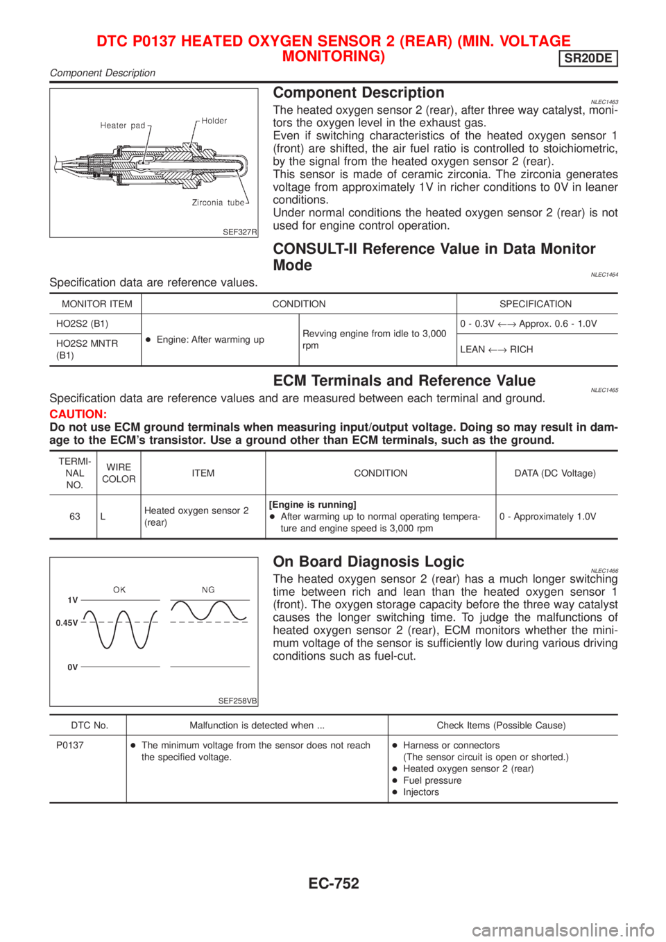
On Board Diagnosis LogicNLEC1466The heated oxygen sensor 2 (rear) has a much longer switching
time between rich and lean than the heated oxygen sensor 1
(front). The oxygen storage capacity before the three way catalyst
causes the longer switching time. To judge the malfunctions of
heated oxygen sensor 2 (rear), ECM monitors whether the mini-
mum voltage of the sensor is sufficiently low during various driving
conditions such as fuel-cut.
DTC No. Malfunction is detected when ... Check Items (Possible Cause)
P0137+The minimum voltage from the sensor does not reach
the specified voltage.+Harness or connectors
(The sensor circuit is open or shorted.)
+Heated oxygen sensor 2 (rear)
+Fuel pressure
+Injectors
DTC P0137 HEATED OXYGEN SENSOR 2 (REAR) (MIN. VOLTAGE
MONITORING)
SR20DE
Component Description
EC-752
Page 1186 of 3051
SEF327R
Component DescriptionNLEC1472The heated oxygen sensor 2 (rear), after three way catalyst, moni-
tors the oxygen level in the exhaust gas.
Even if switching characteristics of the heated oxygen sensor 1
(front) are shifted, the air fuel ratio is controlled to stoichiometric,
by the signal from the heated oxygen sensor 2 (rear).
This sensor is made of ceramic zirconia. The zirconia generates
voltage from approximately 1V in richer conditions to 0V in leaner
conditions.
Under normal conditions the heated oxygen sensor 2 (rear) is not
used for engine control operation.
CONSULT-II Reference Value in Data Monitor
Mode
NLEC1473Specification data are reference values.
MONITOR ITEM CONDITION SPECIFICATION
HO2S2 (B1)
+Engine: After warming upRevving engine from idle to 3,000
rpm0 - 0.3V¨Approx. 0.6 - 1.0V
HO2S2 MNTR
(B1)LEAN¨RICH
ECM Terminals and Reference ValueNLEC1474Specification data are reference values and are measured between each terminal and ground.
CAUTION:
Do not use ECM ground terminals when measuring input/output voltage. Doing so may result in dam-
age to the ECM's transistor. Use a ground other than ECM terminals, such as the ground.
TERMI-
NAL
NO.WIRE
COLORITEM CONDITION DATA (DC Voltage)
63 LHeated oxygen sensor 2
(rear)[Engine is running]
+After warming up to normal operating tempera-
ture and engine speed is 2,000 rpm0 - Approximately 1.0V
SEF259VA
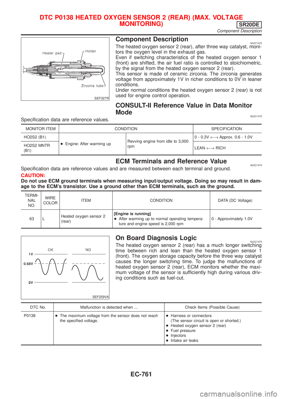
On Board Diagnosis LogicNLEC1475The heated oxygen sensor 2 (rear) has a much longer switching
time between rich and lean than the heated oxygen sensor 1
(front). The oxygen storage capacity before the three way catalyst
causes the longer switching time. To judge the malfunctions of
heated oxygen sensor 2 (rear), ECM monitors whether the maxi-
mum voltage of the sensor is sufficiently high during various driv-
ing conditions such as fuel-cut.
DTC No. Malfunction is detected when ... Check Items (Possible Cause)
P0138+The maximum voltage from the sensor does not reach
the specified voltage.+Harness or connectors
(The sensor circuit is open or shorted.)
+Heated oxygen sensor 2 (rear)
+Fuel pressure
+Injectors
+Intake air leaks
DTC P0138 HEATED OXYGEN SENSOR 2 (REAR) (MAX. VOLTAGE
MONITORING)
SR20DE
Component Description
EC-761
Page 1195 of 3051
SEF327R
Component DescriptionNLEC1481The heated oxygen sensor 2 (rear), after three way catalyst, moni-
tors the oxygen level in the exhaust gas.
Even if switching characteristics of the heated oxygen sensor 1
(front) are shifted, the air fuel ratio is controlled to stoichiometric,
by the signal from the heated oxygen sensor 2 (rear).
This sensor is made of ceramic zirconia. The zirconia generates
voltage from approximately 1V in richer conditions to 0V in leaner
conditions.
Under normal conditions the heated oxygen sensor 2 (rear) is not
used for engine control operation.
CONSULT-II Reference Value in Data Monitor
Mode
NLEC1482Specification data are reference values.
MONITOR ITEM CONDITION SPECIFICATION
HO2S2 (B1)
+Engine: After warming upRevving engine from idle to 3,000
rpm0 - 0.3V¨Approx. 0.6 - 1.0V
HO2S2 MNTR
(B1)LEAN¨RICH
ECM Terminals and Reference ValueNLEC1483Specification data are reference values and are measured between each terminal and ground.
CAUTION:
Do not use ECM ground terminals when measuring input/output voltage. Doing so may result in dam-
age to the ECM's transistor. Use a ground other than ECM terminals, such as the ground.
TERMI-
NAL
NO.WIRE
COLORITEM CONDITION DATA (DC Voltage)
63 LHeated oxygen sensor 2
(rear)[Engine is running]
+After warming up to normal operating tempera-
ture and revving engine from idle to 2,000 rpm0 - Approximately 1.0V
SEF302U
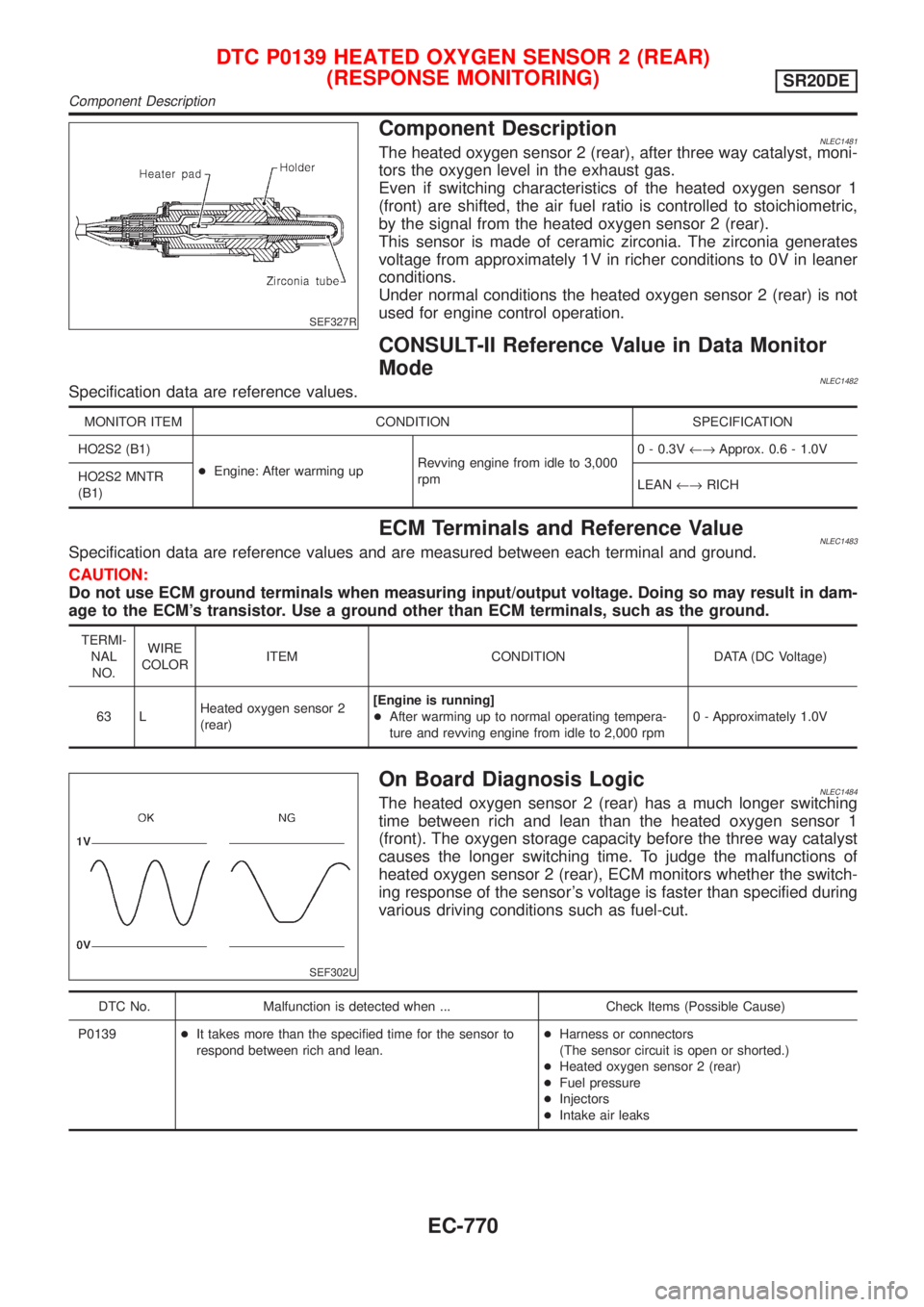
On Board Diagnosis LogicNLEC1484The heated oxygen sensor 2 (rear) has a much longer switching
time between rich and lean than the heated oxygen sensor 1
(front). The oxygen storage capacity before the three way catalyst
causes the longer switching time. To judge the malfunctions of
heated oxygen sensor 2 (rear), ECM monitors whether the switch-
ing response of the sensor's voltage is faster than specified during
various driving conditions such as fuel-cut.
DTC No. Malfunction is detected when ... Check Items (Possible Cause)
P0139+It takes more than the specified time for the sensor to
respond between rich and lean.+Harness or connectors
(The sensor circuit is open or shorted.)
+Heated oxygen sensor 2 (rear)
+Fuel pressure
+Injectors
+Intake air leaks
DTC P0139 HEATED OXYGEN SENSOR 2 (REAR)
(RESPONSE MONITORING)
SR20DE
Component Description
EC-770