Page 2269 of 3051
Removal and InstallationNLEM0006
YEM002
1. Oil pressure switch
2. EGR valve
3. EGR tube
4. Air relief plug
5. Intake manifold6. Intake manifold upper support
7. Intake manifold lower supports
8. Oil filter
9. Thermostat
10. Water pump11. Water pump pulley
12. EGR solenoid valve
13. EGR guide tube
14. EGR gas temperature sensor
OUTER COMPONENT PARTSQG
Removal and Installation
EM-12
Page 2275 of 3051
SMA373C
Changing Air Cleaner FilterNLEM0043VISCOUS PAPER TYPENLEM0043S01The viscous paper type filter does not need cleaning between
renewals.
AIR CLEANERQG
Changing Air Cleaner Filter
EM-18
Page 2345 of 3051
NMA006
Changing Air Cleaner FilterNLEM0120VISCOUS PAPER TYPENLEM0120S01Unfasten clamps to change air cleaner filter.
The viscous paper type filter does not need cleaning.
AIR CLEANERSR
Changing Air Cleaner Filter
EM-88
Page 2426 of 3051
Changing Air Cleaner FilterNLEM0092VISCOUS PAPER TYPENLEM0092S01The viscous paper type filter does not need cleaning.
AIR CLEANERYD
Changing Air Cleaner Filter
EM-169
Page 2524 of 3051

SMA803A
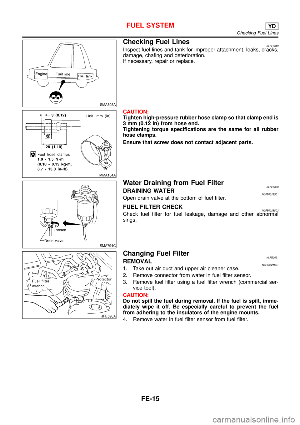
Checking Fuel LinesNLFE0019Inspect fuel lines and tank for improper attachment, leaks, cracks,
damage, chafing and deterioration.
If necessary, repair or replace.
MMA104A
CAUTION:
Tighten high-pressure rubber hose clamp so that clamp end is
3 mm (0.12 in) from hose end.
Tightening torque specifications are the same for all rubber
hose clamps.
Ensure that screw does not contact adjacent parts.
SMA794C
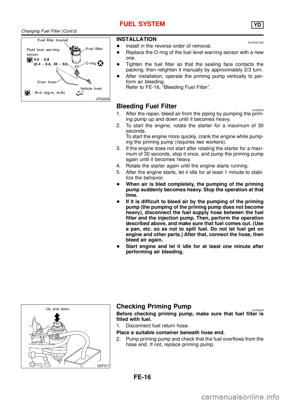
Water Draining from Fuel FilterNLFE0028DRAINING WATERNLFE0028S01Open drain valve at the bottom of fuel filter.
FUEL FILTER CHECKNLFE0028S02Check fuel filter for fuel leakage, damage and other abnormal
sings.
JFE598A
Changing Fuel FilterNLFE0021REMOVALNLFE0021S011. Take out air duct and upper air cleaner case.
2. Remove connector from water in fuel filter sensor.
3. Remove fuel filter using a fuel filter wrench (commercial ser-
vice tool).
CAUTION:
Do not spill the fuel during removal. If the fuel is spilt, imme-
diately wipe it off. Be especially careful to prevent the fuel
from adhering to the insulators of the engine mounts.
4. Remove water in fuel filter sensor from fuel filter.
FUEL SYSTEMYD
Checking Fuel Lines
FE-15
Page 2525 of 3051

JFE624A
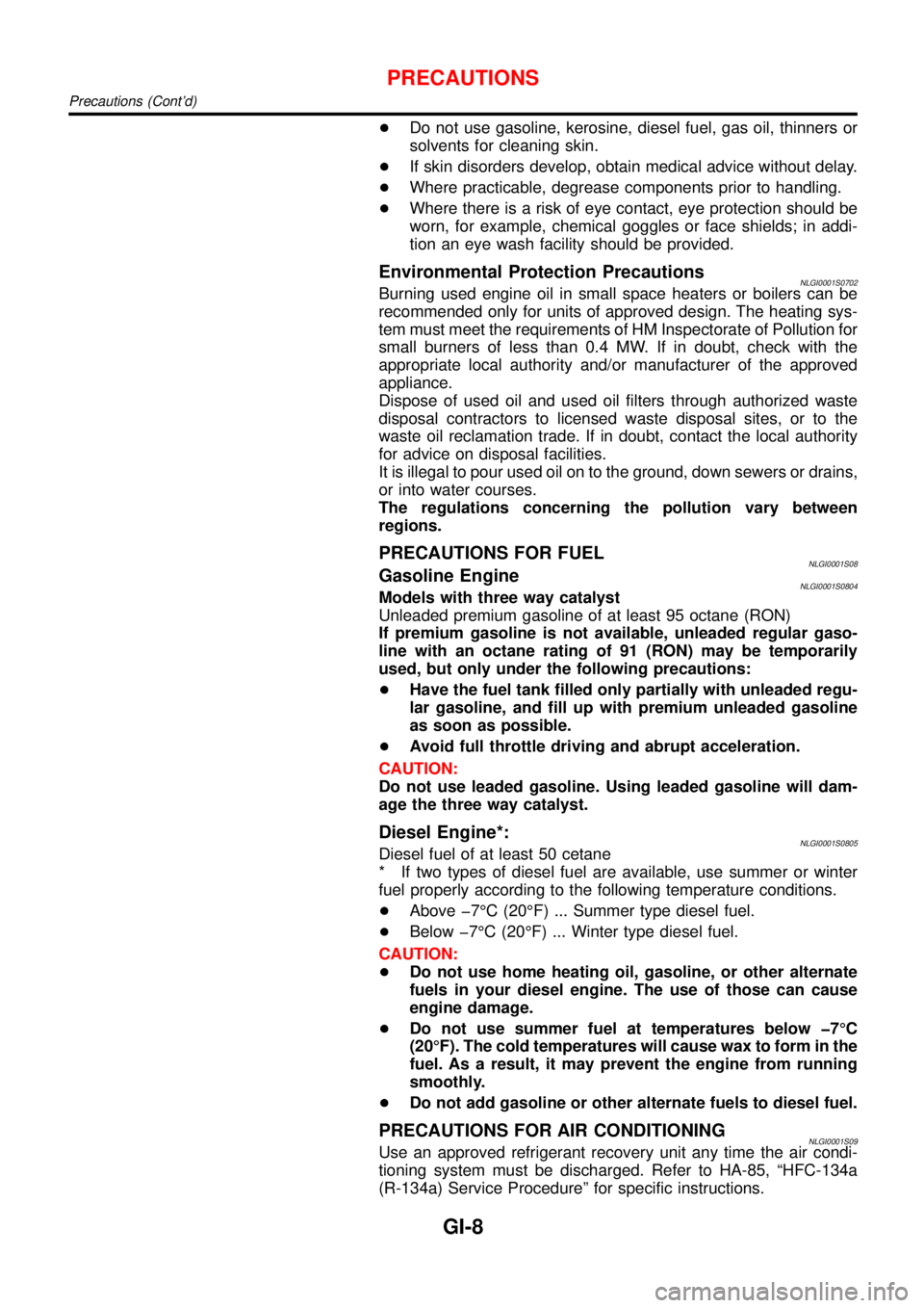
INSTALLATIONNLFE0021S02+Install in the reverse order of removal.
+Replace the O-ring of the fuel level warning sensor with a new
one.
+Tighten the fuel filter so that the sealing face contacts the
packing, then retighten it manually by approximately 2/3 turn.
+After installation, operate the priming pump vertically to per-
form air bleeding.
Refer to FE-16,“Bleeding Fuel Filter”.
Bleeding Fuel FilterNLFE00231. After the repair, bleed air from the piping by pumping the prim-
ing pump up and down until it becomes heavy.
2. To start the engine, rotate the starter for a maximum of 30
seconds.
To start the engine more quickly, crank the engine while pump-
ing the priming pump (requires two workers).
3. If the engine does not start after rotating the starter for a maxi-
mum of 30 seconds, stop it once, and pump the priming pump
again until it becomes heavy.
4. Rotate the starter again until the engine starts running.
5. After the engine starts, let it idle for at least 1 minute to stabi-
lize the behavior.
+When air is bled completely, the pumping of the priming
pump suddenly becomes heavy. Stop the operation at that
time.
+If it is difficult to bleed air by the pumping of the priming
pump (the pumping of the priming pump does not become
heavy), disconnect the fuel supply hose between the fuel
filter and the injection pump. Then, perform the operation
described above, and make sure that fuel comes out. (Use
a pan, etc. so as not to spill fuel. Do not let fuel get on
engine and other parts.) After that, connect the hose, then
bleed air again.
+Start engine and let it idle for at least one minute after
performing air bleeding.
DEF017
Checking Priming PumpNLFE0024Before checking priming pump, make sure that fuel filter is
filled with fuel.
1. Disconnect fuel return hose.
Place a suitable container beneath hose end.
2. Pump priming pump and check that the fuel overflows from the
hose end. If not, replace priming pump.
FUEL SYSTEMYD
Changing Fuel Filter (Cont’d)
FE-16
Page 2547 of 3051

+Do not use gasoline, kerosine, diesel fuel, gas oil, thinners or
solvents for cleaning skin.
+If skin disorders develop, obtain medical advice without delay.
+Where practicable, degrease components prior to handling.
+Where there is a risk of eye contact, eye protection should be
worn, for example, chemical goggles or face shields; in addi-
tion an eye wash facility should be provided.
Environmental Protection PrecautionsNLGI0001S0702Burning used engine oil in small space heaters or boilers can be
recommended only for units of approved design. The heating sys-
tem must meet the requirements of HM Inspectorate of Pollution for
small burners of less than 0.4 MW. If in doubt, check with the
appropriate local authority and/or manufacturer of the approved
appliance.
Dispose of used oil and used oil filters through authorized waste
disposal contractors to licensed waste disposal sites, or to the
waste oil reclamation trade. If in doubt, contact the local authority
for advice on disposal facilities.
It is illegal to pour used oil on to the ground, down sewers or drains,
or into water courses.
The regulations concerning the pollution vary between
regions.
PRECAUTIONS FOR FUELNLGI0001S08Gasoline EngineNLGI0001S0804Models with three way catalyst
Unleaded premium gasoline of at least 95 octane (RON)
If premium gasoline is not available, unleaded regular gaso-
line with an octane rating of 91 (RON) may be temporarily
used, but only under the following precautions:
+Have the fuel tank filled only partially with unleaded regu-
lar gasoline, and fill up with premium unleaded gasoline
as soon as possible.
+Avoid full throttle driving and abrupt acceleration.
CAUTION:
Do not use leaded gasoline. Using leaded gasoline will dam-
age the three way catalyst.
Diesel Engine*:NLGI0001S0805Diesel fuel of at least 50 cetane
* If two types of diesel fuel are available, use summer or winter
fuel properly according to the following temperature conditions.
+Above �7°C (20°F) ... Summer type diesel fuel.
+Below �7°C (20°F) ... Winter type diesel fuel.
CAUTION:
+Do not use home heating oil, gasoline, or other alternate
fuels in your diesel engine. The use of those can cause
engine damage.
+Do not use summer fuel at temperatures below �7°C
(20°F). The cold temperatures will cause wax to form in the
fuel. As a result, it may prevent the engine from running
smoothly.
+Do not add gasoline or other alternate fuels to diesel fuel.
PRECAUTIONS FOR AIR CONDITIONINGNLGI0001S09Use an approved refrigerant recovery unit any time the air condi-
tioning system must be discharged. Refer to HA-85, “HFC-134a
(R-134a) Service Procedure” for specific instructions.
PRECAUTIONS
Precautions (Cont’d)
GI-8
Page 2592 of 3051

HEATER &
AIR CONDITIONER
SECTION
HA
CONTENTS
PRECAUTIONS...............................................................2
Supplemental Restraint System (SRS)″AIR
BAG″and″SEAT BELT PRE-TENSIONER″...............2
Precautions for Working with HFC-134a (R-134a) .....2
General Refrigerant Precautions .................................2
Precautions for Refrigerant Connection ......................3
Precautions for Servicing Compressor ........................5
Precautions for Service Equipment .............................6
Wiring Diagrams and Trouble Diagnosis .....................8
PREPARATION...............................................................9
Special Service Tools ..................................................9
HFC-134a (R-134a) Service Tools and
Equipment ..................................................................10
DESCRIPTION...............................................................12
Refrigeration System .................................................12
CSV613 Variable Displacement Compressor............13
Component Layout ....................................................17
Control Operation ......................................................18
Discharge Air Flow.....................................................19
System Description ....................................................20
TROUBLE DIAGNOSES................................................21
Component Location..................................................21
Wiring Diagram - Heater............................................23
Circuit Diagram - Air Conditioner...............................26
Wiring Diagram - A/C, M - .........................................27
How to Perform Trouble Diagnoses for Quick
and Accurate Repair ..................................................40
Operational Check .....................................................41Intake Door ................................................................43
Mode Door .................................................................47
Air Mix Door ...............................................................49
Max Hot Door (For Scandinavia and Cold Spec
Models) ......................................................................51
Blower Motor..............................................................55
Magnet Clutch............................................................62
Insufficient Cooling ....................................................75
Insufficient Heating ....................................................83
Noise ..........................................................................84
SERVICE PROCEDURE................................................85
HFC-134a (R-134a) Service Procedure ....................85
Maintenance of Lubricant Quantity in
Compressor ...............................................................87
Compressor ...............................................................90
Compressor Clutch - CSV613 (CALSONIC
make) .........................................................................92
Heater & Cooling Unit (Heater Core) ........................95
A/C Evaporator ..........................................................96
Blower Unit ................................................................97
Refrigerant Lines .......................................................98
Belt ...........................................................................102
Idle Air Control Valve (IACV) - Auxiliary Air
Control (AAC) Valve ................................................103
Ventilation Air Filter ..................................................103
SERVICE DATA AND SPECIFICATIONS (SDS).......104
Manual .....................................................................104