Page 3008 of 3051
Disassembly and Assembly=NLST0019
NST048
1. Combination switch
2. Column shaft assembly3. Clip
4. Lower seal cover5. Hole cover
SST741A
+Steering lock
a) Break self-shear type screws with a drill or other appropriate
tool.
SST742A
b) Install new self-shear type screws and then cut off self-shear
type screw heads.
STEERING WHEEL AND STEERING COLUMN
Disassembly and Assembly
ST-13
Page 3009 of 3051
SST855C
InspectionNLST0020+When steering wheel does not turn smoothly, check the steer-
ing column as follows and replace damaged parts.
a) Check column bearings for damage or unevenness. Lubricate
with recommended multi-purpose grease or replace steering
column as an assembly, if necessary.
b) Check jacket tube for deformation or breakage. Replace if
necessary.
+When the vehicle comes into a light collision, check length“L”.
Steering column length“L”:
Refer to SDS, ST-27.
If out of the specifications, replace steering column as an assem-
bly.
NST049
TILT MECHANISMNLST0020S01+After installing steering column, check tilt mechanism opera-
tion.
STEERING WHEEL AND STEERING COLUMN
Inspection
ST-14
Page 3011 of 3051
Removal and InstallationNLST0022
NST050
1. Lower joint
2. Washer
3. Gear and linkage assembly4. Upper gear housing mounting
bracket
5. Rack mounting insulator6. Lower gear housing mounting
bracket
7. Cotter pin
SFA455BA
CAUTION:
+The rotation of the spiral cable (SRS“Air bag”component
part) is limited. If the steering gear must be removed, set
the front wheels in the straight-ahead direction. Do not
rotate the steering column while the steering gear is
removed.
+Remove the steering wheel before removing the steering
lower joint to avoid damaging the SRS spiral cable.
+Detach tie-rod outer sockets from knuckle arms with Tool.
1. Remove stabilizer fixing bolts. Refer to SU-12,“Removal and
Installation”.
2. Disconnect lower joint.
3. Remove gear housing mounting bracket fixing bolts.
4. Remove steering gear assembly.
POWER STEERING GEAR AND LINKAGE
Removal and Installation
ST-16
Page 3012 of 3051

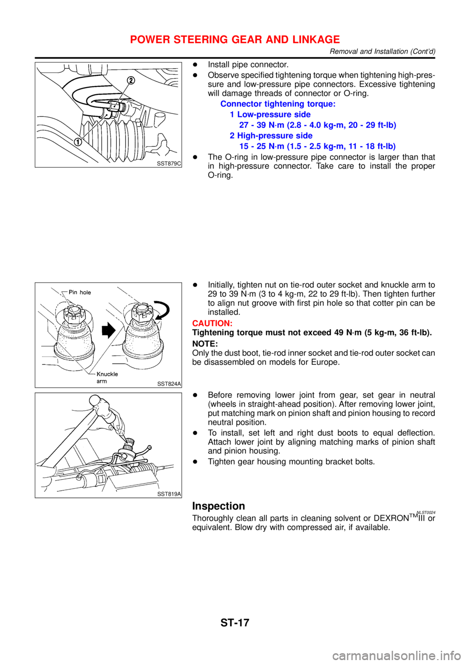
SST879C
+Install pipe connector.
+Observe specified tightening torque when tightening high-pres-
sure and low-pressure pipe connectors. Excessive tightening
will damage threads of connector or O-ring.
Connector tightening torque:
1 Low-pressure side
27-39N·m (2.8 - 4.0 kg-m, 20 - 29 ft-lb)
2 High-pressure side
15-25N·m (1.5 - 2.5 kg-m, 11 - 18 ft-lb)
+The O-ring in low-pressure pipe connector is larger than that
in high-pressure connector. Take care to install the proper
O-ring.
SST824A
+Initially, tighten nut on tie-rod outer socket and knuckle arm to
29 to 39 N·m (3 to 4 kg-m, 22 to 29 ft-lb). Then tighten further
to align nut groove with first pin hole so that cotter pin can be
installed.
CAUTION:
Tightening torque must not exceed 49 N·m (5 kg-m, 36 ft-lb).
NOTE:
Only the dust boot, tie-rod inner socket and tie-rod outer socket can
be disassembled on models for Europe.
SST819A
+Before removing lower joint from gear, set gear in neutral
(wheels in straight-ahead position). After removing lower joint,
put matching mark on pinion shaft and pinion housing to record
neutral position.
+To install, set left and right dust boots to equal deflection.
Attach lower joint by aligning matching marks of pinion shaft
and pinion housing.
+Tighten gear housing mounting bracket bolts.
InspectionNLST0024Thoroughly clean all parts in cleaning solvent or DEXRONTMIII or
equivalent. Blow dry with compressed air, if available.
POWER STEERING GEAR AND LINKAGE
Removal and Installation (Cont’d)
ST-17
Page 3022 of 3051
General SpecificationsNLST0032
Applied model
Steering modelPower steering
Steering gear typePR25T
Steering overall gear ratio18.07
Turns of steering wheel (Lock to lock)3.26
Steering column typeCollapsible, tilt
Steering WheelNLST0033
Steering wheel axial play mm (in)0 (0)
Steering wheel play mm (in)35 (1.38) or less
Movement of gear housing mm (in)±2(±0.08) or less
Steering ColumnNLST0034
Steering column length“L”mm (in) 535 - 537 (21.06 - 21.14)
SST855C
SERVICE DATA AND SPECIFICATIONS (SDS)
General Specifications
ST-27
Page 3023 of 3051

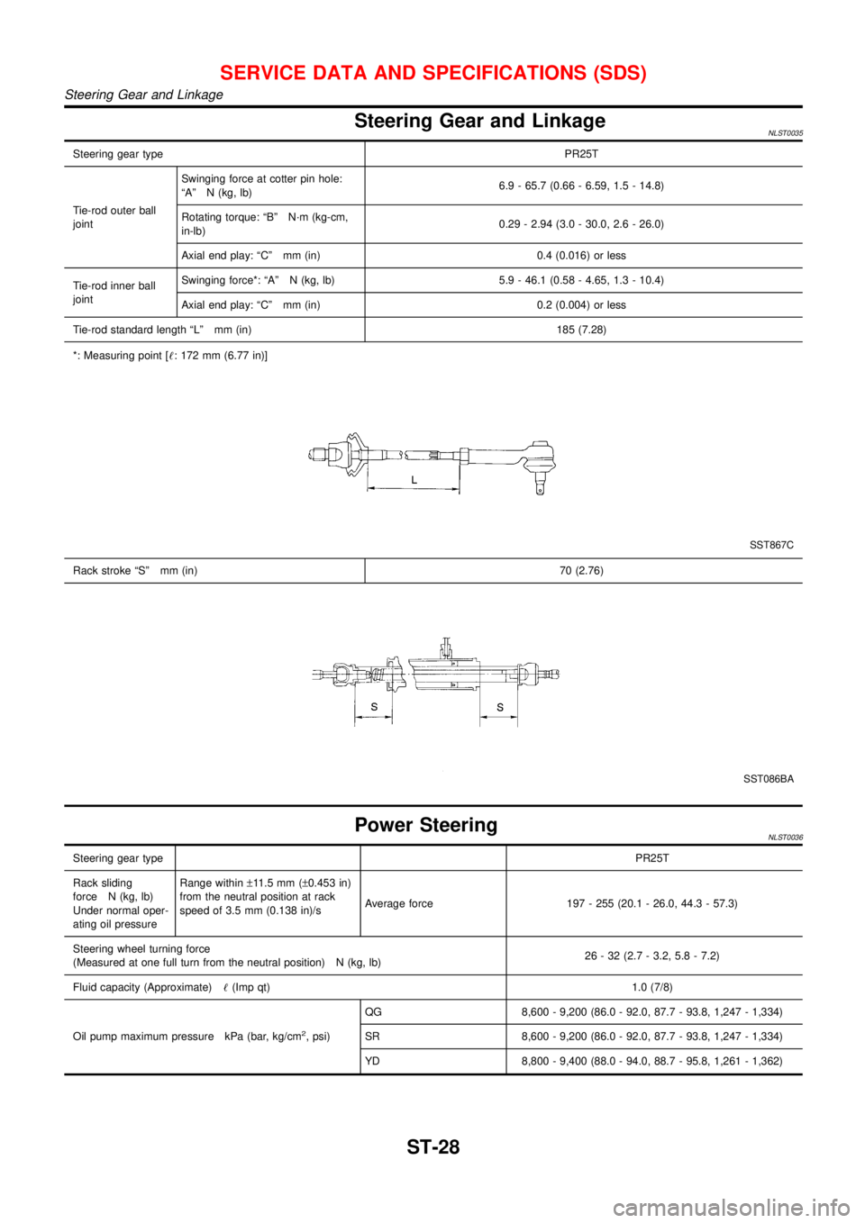
Steering Gear and LinkageNLST0035
Steering gear typePR25T
Tie-rod outer ball
jointSwinging force at cotter pin hole:
“A”N (kg, lb)6.9 - 65.7 (0.66 - 6.59, 1.5 - 14.8)
Rotating torque:“B”N·m (kg-cm,
in-lb)0.29 - 2.94 (3.0 - 30.0, 2.6 - 26.0)
Axial end play:“C”mm (in) 0.4 (0.016) or less
Tie-rod inner ball
jointSwinging force*:“A”N (kg, lb) 5.9 - 46.1 (0.58 - 4.65, 1.3 - 10.4)
Axial end play:“C”mm (in) 0.2 (0.004) or less
Tie-rod standard length“L”mm (in) 185 (7.28)
*: Measuring point [!: 172 mm (6.77 in)]
SST867C
Rack stroke“S”mm (in)70 (2.76)
SST086BA
Power SteeringNLST0036
Steering gear typePR25T
Rack sliding
force N (kg, lb)
Under normal oper-
ating oil pressureRange within±11.5 mm (±0.453 in)
from the neutral position at rack
speed of 3.5 mm (0.138 in)/sAverage force 197 - 255 (20.1 - 26.0, 44.3 - 57.3)
Steering wheel turning force
(Measured at one full turn from the neutral position) N (kg, lb)26 - 32 (2.7 - 3.2, 5.8 - 7.2)
Fluid capacity (Approximate)!(Imp qt)1.0 (7/8)
Oil pump maximum pressure kPa (bar, kg/cm
2, psi)QG 8,600 - 9,200 (86.0 - 92.0, 87.7 - 93.8, 1,247 - 1,334)
SR 8,600 - 9,200 (86.0 - 92.0, 87.7 - 93.8, 1,247 - 1,334)
YD 8,800 - 9,400 (88.0 - 94.0, 88.7 - 95.8, 1,261 - 1,362)
SERVICE DATA AND SPECIFICATIONS (SDS)
Steering Gear and Linkage
ST-28
Page 3024 of 3051

FRONT & REAR SUSPENSION
SECTION
SU
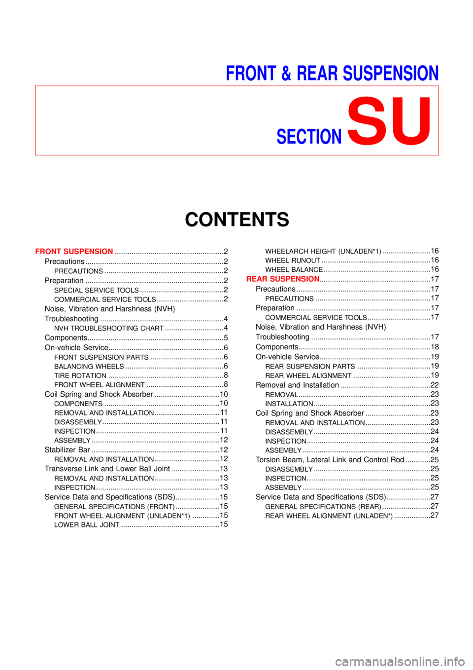
CONTENTS
FRONT SUSPENSION....................................................2
Precautions ..................................................................2
PRECAUTIONS.........................................................2
Preparation ..................................................................2
SPECIAL SERVICE TOOLS........................................2
COMMERCIAL SERVICE TOOLS................................2
Noise, Vibration and Harshness (NVH)
Troubleshooting ...........................................................4
NVH TROUBLESHOOTING CHART............................4
Components.................................................................5
On-vehicle Service.......................................................6
FRONT SUSPENSION PARTS...................................6
BALANCING WHEELS...............................................6
TIRE ROTATION.......................................................8
FRONT WHEEL ALIGNMENT.....................................8
Coil Spring and Shock Absorber ...............................10
COMPONENTS.......................................................10
REMOVAL AND INSTALLATION............................... 11
DISASSEMBLY........................................................ 11
INSPECTION........................................................... 11
ASSEMBLY.............................................................12
Stabilizer Bar .............................................................12
REMOVAL AND INSTALLATION...............................12
Transverse Link and Lower Ball Joint .......................13
REMOVAL AND INSTALLATION...............................13
INSPECTION...........................................................13
Service Data and Specifications (SDS).....................15
GENERAL SPECIFICATIONS (FRONT).....................15
FRONT WHEEL ALIGNMENT (UNLADEN*1).............15
LOWER BALL JOINT...............................................15
WHEELARCH HEIGHT (UNLADEN*1).......................16
WHEEL RUNOUT....................................................16
WHEEL BALANCE...................................................16
REAR SUSPENSION.....................................................17
Precautions ................................................................17
PRECAUTIONS.......................................................17
Preparation ................................................................17
COMMERCIAL SERVICE TOOLS..............................17
Noise, Vibration and Harshness (NVH)
Troubleshooting .........................................................17
Components...............................................................18
On-vehicle Service.....................................................19
REAR SUSPENSION PARTS...................................19
REAR WHEEL ALIGNMENT.....................................19
Removal and Installation ...........................................22
REMOVAL...............................................................23
INSTALLATION........................................................23
Coil Spring and Shock Absorber ...............................23
REMOVAL AND INSTALLATION...............................23
DISASSEMBLY........................................................24
INSPECTION...........................................................24
ASSEMBLY.............................................................24
Torsion Beam, Lateral Link and Control Rod ............25
DISASSEMBLY........................................................25
INSPECTION...........................................................25
ASSEMBLY.............................................................25
Service Data and Specifications (SDS).....................27
GENERAL SPECIFICATIONS (REAR).......................27
REAR WHEEL ALIGNMENT (UNLADEN*).................27
Page 3025 of 3051

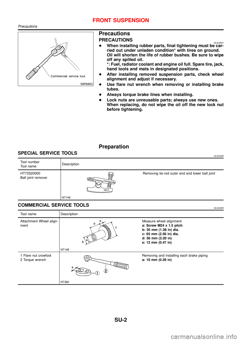
SBR686C
Precautions
PRECAUTIONSNLSU0001+When installing rubber parts, final tightening must be car-
ried out under unladen condition* with tires on ground.
Oil will shorten the life of rubber bushes. Be sure to wipe
off any spilled oil.
*: Fuel, radiator coolant and engine oil full. Spare tire, jack,
hand tools and mats in designated positions.
+After installing removed suspension parts, check wheel
alignment and adjust if necessary.
+Use flare nut wrench when removing or installing brake
tubes.
+Always torque brake lines when installing.
+Lock nuts are unreusable parts; always use new ones.
When replacing, do not wipe the oil off the new lock nut
before tightening.
Preparation
SPECIAL SERVICE TOOLSNLSU0002
Tool number
Tool nameDescription
HT72520000
Ball joint remover
NT146
Removing tie-rod outer end and lower ball joint
COMMERCIAL SERVICE TOOLSNLSU0003
Tool name Description
Attachment Wheel align-
ment
NT148
Measure wheel alignment
a: Screw M24 x 1.5 pitch
b: 35 mm (1.38 in) dia.
c: 65 mm (2.56 in) dia.
d: 56 mm (2.20 in)
e: 12 mm (0.47 in)
1 Flare nut crowfoot
2 Torque wrench
NT360
Removing and installing each brake piping
a: 10 mm (0.39 in)
FRONT SUSPENSION
Precautions
SU-2