2001 NISSAN ALMERA TINO stop start
[x] Cancel search: stop startPage 2702 of 3051

S
S/LOCK - Wiring diagram ................ EL-260, 286
S/SIG - Wiring diagram ................. EC-512, 1028
SAE J1930 terminology list ........................ GI-48
SHIFT - Wiring diagram ........................... AT-196
SROOF - Wiring diagram ........................ EL-238
SRS - See Supplemental Restraint
System ................................................... RS-16
START - Wiring diagram ........................... SC-14
STOP/L - Wiring diagram .......................... EL-91
SWL/V - Wiring diagram ................. EC-366, 481
Seal - See Exterior .................................... BT-38
Seat belt pre-tensioner disposal ............... RS-30
Seat belt pre-tensioner ............................... RS-3
Seat belt, front ............................................ RS-5
Seat belt, rear ............................................. RS-7
Seat, front .................................................. BT-46
Seat, rear ................................................... BT-49
Self-diagnostic results ............ EC-73, 598, 1098
Shift control components (M/T) .......... MT-26, 64
Shift fork (M/T) .................................... MT-26, 64
Shift lever .................................................. MT-23
Shift lock system ...................................... AT-195
Shock absorber (front) .............................. SU-11
Shock absorber (rear) ............................... SU-23
Side air bag ............................................... RS-28
Side trim .................................................... BT-28
Speedometer ........................................... EL-130
Spiral cable ............................................... RS-24
Spring (Wheelarch) height .......................... SU-6
Stabilizer bar (front) .................................. SU-12
Stall test (A/T) ............................................ AT-51
Standardized relay ....................................... EL-7
Start signal .......................... EC-511, 1027, 1293
Starter ....................................................... SC-17
Starting system ......................................... SC-13
Steering linkage ......................................... ST-15
Steering switch .......................................... EL-67
Steering wheel and column ....................... ST-10
Steering wheel play ..................................... ST-6
Steering wheel turning force ....................... ST-8
Stop lamp .................................................. EL-91
Striking rod (M/T) ................................ MT-26, 64
Strut (front) ................................................ SU-10
Strut (rear) ................................................. SU-22
Sub-gear (M/T) .......................................... MT-25
Sunroof, electric ....................................... EL-238
Sunroof ...................................................... BT-51
Super lock ................................................ EL-281
Supplemental Restraint System ............... RS-16
Swirl control valve control solenoid
valve .................................. EC-366, 481, 1285
Symbols and abbreviations .......................... GI-9
Symptom matrix chart ........... EC-124, 648, 1116
Synchronizer (M/T) ............................. MT-25, 63
System readiness test (SRT) code ... EC-62, 586
T
TCM circuit diagram ................................... AT-13
TCM inspection table ................................. AT-58
TP/SW - Wiring diagram ................. EC-354, 874
TPS - Wiring diagram ..................... EC-178, 703
TURN - Wiring diagram ........................... EL-102
Tachometer .............................................. EL-130
Tail lamp .................................................... EL-87
Thermostat .................................... LC-15, 35, 57
Three way catalyst precautions ................... GI-6
Three way catalyst .......................... EC-327, 848
Throttle position sensor (TPS) ........ EC-175, 700
Throttle position sensor adjustment .. EC-99, 623
Throttle position switch ................... AT-111, 145,
EC-352, 872
Throwout bearing - See Clutch release
bearing ............................................. CL-17, 20
Tie-rod ball joints ....................................... ST-18
Tie-rod ........................................................ ST-15
Tightening torque of standard bolts ........... GI-47
Timing belt .......................................... EM-22, 96
Timing chain ........................................... EM-175
Tire size ...................................................... GI-41
Torque converter installation .................... AT-207
Tow truck towing ........................................ GI-45
Transmission case (M/T) .................... MT-24, 62
Tread-FR&RR (Dimensions) ...................... GI-41
Trim ............................................................ BT-28
Trouble diagnoses ...................................... GI-31
Trunk lid finisher ........................................ BT-31
Trunk lid opener - See Trunk lid ................ BT-10
Trunk lid trim .............................................. BT-31
Trunk lid ..................................................... BT-10
Trunk room trim ......................................... BT-31
Turn signal lamp ...................................... EL-101
Two trip detection logic ..................... EC-59, 583
Two-pole lift ................................................ GI-44
U
Under body ................................................ BT-68
V
VSS - Wiring diagram ........... EC-340, 860, 1172
Vacuum hose (brake system) ................... BR-18
Vacuum hose drawing (Engine control) ... EC-33,
567, 1077
Vacuum pump ........................................... BR-20
Valve clearance ................................ EM-42, 214
Valve guide ............................... EM-38, 116, 205
Valve lifter ................................................. EM-41
Valve seat ................................. EM-40, 117, 207
Valve spring .............................. EM-41, 119, 209
ALPHABETICAL INDEX
IDX-7
Page 2731 of 3051
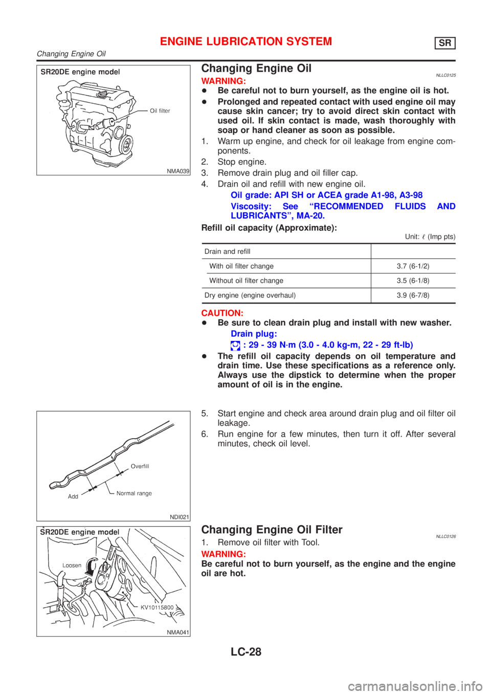
NMA039
Changing Engine OilNLLC0125WARNING:
+Be careful not to burn yourself, as the engine oil is hot.
+Prolonged and repeated contact with used engine oil may
cause skin cancer; try to avoid direct skin contact with
used oil. If skin contact is made, wash thoroughly with
soap or hand cleaner as soon as possible.
1. Warm up engine, and check for oil leakage from engine com-
ponents.
2. Stop engine.
3. Remove drain plug and oil filler cap.
4. Drain oil and refill with new engine oil.
Oil grade: API SH or ACEA grade A1-98, A3-98
Viscosity: See ªRECOMMENDED FLUIDS AND
LUBRICANTSº, MA-20.
Refill oil capacity (Approximate):
Unit:!(Imp pts)
Drain and refill
With oil filter change 3.7 (6-1/2)
Without oil filter change 3.5 (6-1/8)
Dry engine (engine overhaul) 3.9 (6-7/8)
CAUTION:
+Be sure to clean drain plug and install with new washer.
Drain plug:
: 29 - 39 N´m (3.0 - 4.0 kg-m, 22 - 29 ft-lb)
+The refill oil capacity depends on oil temperature and
drain time. Use these specifications as a reference only.
Always use the dipstick to determine when the proper
amount of oil is in the engine.
NDI021
5. Start engine and check area around drain plug and oil filter oil
leakage.
6. Run engine for a few minutes, then turn it off. After several
minutes, check oil level.
NMA041
Changing Engine Oil FilterNLLC01261. Remove oil filter with Tool.
WARNING:
Be careful not to burn yourself, as the engine and the engine
oil are hot.
ENGINE LUBRICATION SYSTEMSR
Changing Engine Oil
LC-28
Page 2750 of 3051
SLC287B
JLC288B
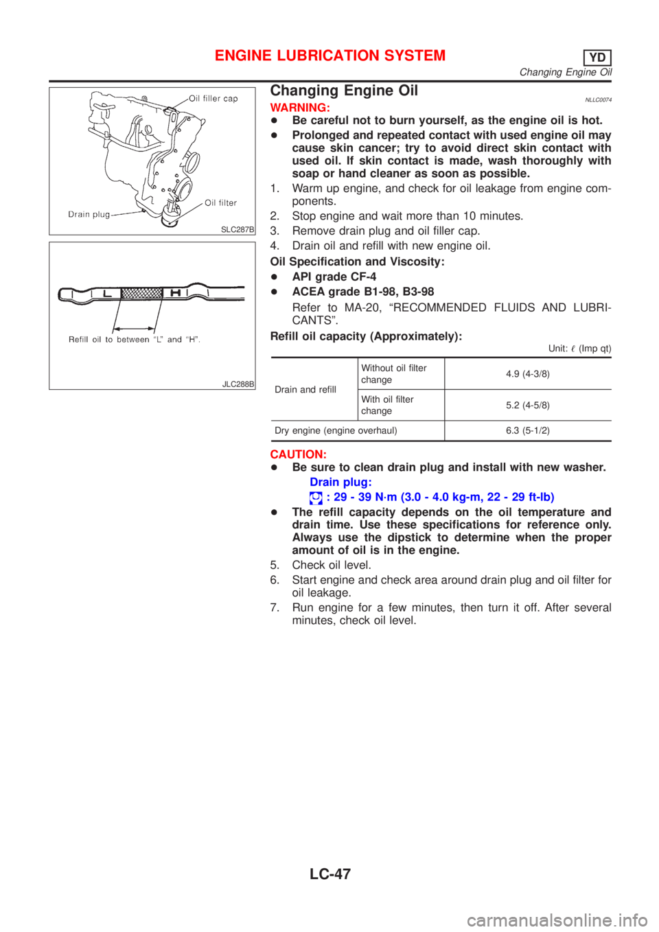
Changing Engine OilNLLC0074WARNING:
+Be careful not to burn yourself, as the engine oil is hot.
+Prolonged and repeated contact with used engine oil may
cause skin cancer; try to avoid direct skin contact with
used oil. If skin contact is made, wash thoroughly with
soap or hand cleaner as soon as possible.
1. Warm up engine, and check for oil leakage from engine com-
ponents.
2. Stop engine and wait more than 10 minutes.
3. Remove drain plug and oil filler cap.
4. Drain oil and refill with new engine oil.
Oil Specification and Viscosity:
+API grade CF-4
+ACEA grade B1-98, B3-98
Refer to MA-20, ªRECOMMENDED FLUIDS AND LUBRI-
CANTSº.
Refill oil capacity (Approximately):
Unit:!(Imp qt)
Drain and refillWithout oil filter
change4.9 (4-3/8)
With oil filter
change5.2 (4-5/8)
Dry engine (engine overhaul) 6.3 (5-1/2)
CAUTION:
+Be sure to clean drain plug and install with new washer.
Drain plug:
: 29 - 39 N´m (3.0 - 4.0 kg-m, 22 - 29 ft-lb)
+The refill capacity depends on the oil temperature and
drain time. Use these specifications for reference only.
Always use the dipstick to determine when the proper
amount of oil is in the engine.
5. Check oil level.
6. Start engine and check area around drain plug and oil filter for
oil leakage.
7. Run engine for a few minutes, then turn it off. After several
minutes, check oil level.
ENGINE LUBRICATION SYSTEMYD
Changing Engine Oil
LC-47
Page 2970 of 3051
![NISSAN ALMERA TINO 2001 Service Repair Manual Fig. 2 INITIAL CHARGING CURRENT SETTING (Slow charge)
CON-
VERTED
SPECIFIC
GRAVITYBATTERY TYPE
28B19R(L)
34B19R(L)
46B24R(L)
55B24R(L)
079 [YUASA type code]
50D23R(L)
55D23R(L)
025 [YUASA type code]
0 NISSAN ALMERA TINO 2001 Service Repair Manual Fig. 2 INITIAL CHARGING CURRENT SETTING (Slow charge)
CON-
VERTED
SPECIFIC
GRAVITYBATTERY TYPE
28B19R(L)
34B19R(L)
46B24R(L)
55B24R(L)
079 [YUASA type code]
50D23R(L)
55D23R(L)
025 [YUASA type code]
0](/manual-img/5/57352/w960_57352-2969.png)
Fig. 2 INITIAL CHARGING CURRENT SETTING (Slow charge)
CON-
VERTED
SPECIFIC
GRAVITYBATTERY TYPE
28B19R(L)
34B19R(L)
46B24R(L)
55B24R(L)
079 [YUASA type code]
50D23R(L)
55D23R(L)
025 [YUASA type code]
027 [YUASA type code]
65D26R(L)
80D26R(L)
067 [YUASA type code]
096 [YUASA type code]
75D31R(L)
065 [YUASA type code]
075 [YUASA type code]
95D31R(L)
115D31R(L)
110D26R(L)
95E41R(L)
130E41R(L)
Below 1.100 4.0 (A) 5.0 (A) 7.0 (A) 8.0 (A)8.5
(A)9.0
(A)10.0 (A)14.0
(A)
+Check battery type and determine the specified current using the table shown above.
+After starting charging, adjustment of charging current is not necessary.
Fig. 3 ADDITIONAL CHARGE (Slow charge)
SEL757W
*: SC-7
CAUTION:
+Set charging current to value specified in Fig. 2. If charger is not capable of producing specified
current value, set its charging current as close to that value as possible.
+Keep battery away from open flame while it is being charged.
+When connecting charger, connect leads first, then turn on charger. Do not turn on charger first,
as this may cause a spark.
+If battery temperature rises above 60°C (140°F), stop charging. Always charge battery when its
temperature is below 60°C (140°F).
BATTERY
Battery Test and Charging Chart (Cont’d)
SC-9
Page 2973 of 3051
![NISSAN ALMERA TINO 2001 Service Repair Manual Fig. 6 INITIAL CHARGING CURRENT SETTING AND CHARGING TIME (Quick charge)
BATTERY
TYPE
28B19R(L)
34B19R(L)
46B24R(L)
55B24R(L)
50D23R(L)
079 [YUASA type code]
55D23R(L)
65D26R(L)
80D26R(L)
025 [YUASA t NISSAN ALMERA TINO 2001 Service Repair Manual Fig. 6 INITIAL CHARGING CURRENT SETTING AND CHARGING TIME (Quick charge)
BATTERY
TYPE
28B19R(L)
34B19R(L)
46B24R(L)
55B24R(L)
50D23R(L)
079 [YUASA type code]
55D23R(L)
65D26R(L)
80D26R(L)
025 [YUASA t](/manual-img/5/57352/w960_57352-2972.png)
Fig. 6 INITIAL CHARGING CURRENT SETTING AND CHARGING TIME (Quick charge)
BATTERY
TYPE
28B19R(L)
34B19R(L)
46B24R(L)
55B24R(L)
50D23R(L)
079 [YUASA type code]
55D23R(L)
65D26R(L)
80D26R(L)
025 [YUASA type code]
027 [YUASA type code]
065 [YUASA type code]
075 [YUASA type code]
067 [YUASA type code]
096 [YUASA type code]
75D31R(L)
95D31R(L)
115D31R(L)
110D26R(L)
95E41R(L)
130E41R(L)
CURRENT
[A]10 (A) 15 (A) 20 (A) 25 (A) 30 (A)40
(A)
CONVERTED SPECIFIC GRAVITY
1.100 -
1.1302.5 hours
1.130 -
1.1602.0 hours
1.160 -
1.1901.5 hours
1.190 -
1.2201.0 hours
Above
1.2200.75 hours (45 min.)
+Check battery type and determine the specified current using the table shown above.
+After starting charging, adjustment of charging current is not necessary.
CAUTION:
+Do not use quick charge method on a battery whose specific gravity is less than 1.100.
+Set initial charging current to value specified in Fig. 6. If charger is not capable of producing
specified current value, set its charging current as close to that value as possible.
+Keep battery away from open flame while it is being charged.
+When connecting charger, connect leads first, then turn on charger. Do not turn on charger first,
as this may cause a spark.
+Be careful of a rise in battery temperature because a large current flow is required during quick-
charge operation.
If battery temperature rises above 60°C (140°F), stop charging. Always charge battery when its
temperature is below 60°C (140°F).
+Do not exceed the charging time specified in Fig. 6, because charging battery over the charging
time can cause deterioration of the battery.
BATTERY
Battery Test and Charging Chart (Cont’d)
SC-12
Page 2984 of 3051
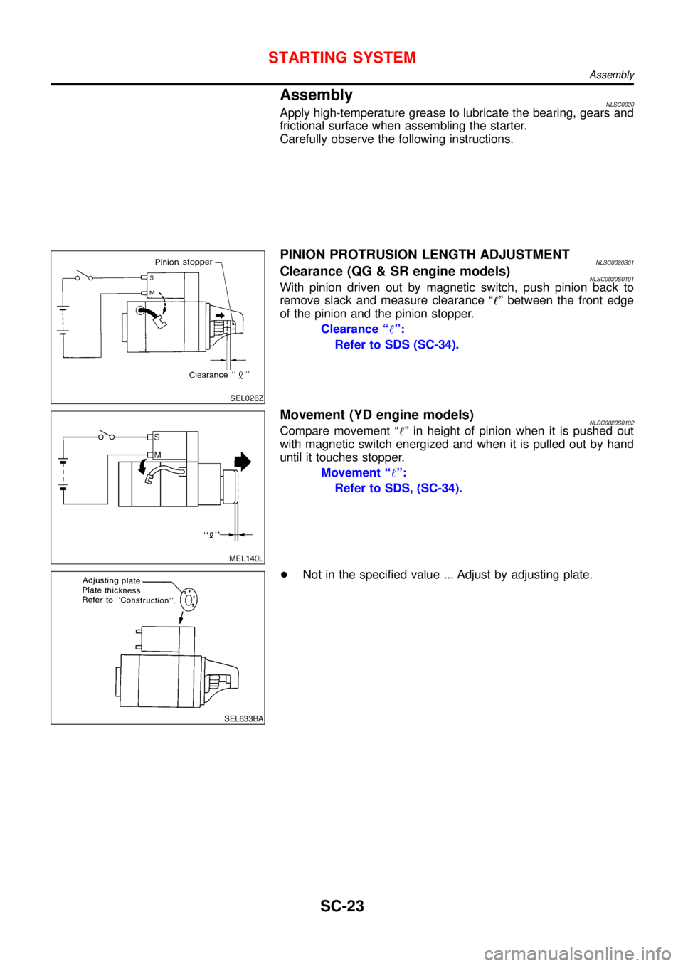
AssemblyNLSC0020Apply high-temperature grease to lubricate the bearing, gears and
frictional surface when assembling the starter.
Carefully observe the following instructions.
SEL026Z
PINION PROTRUSION LENGTH ADJUSTMENTNLSC0020S01Clearance (QG & SR engine models)NLSC0020S0101With pinion driven out by magnetic switch, push pinion back to
remove slack and measure clearance“!”between the front edge
of the pinion and the pinion stopper.
Clearance“!”:
Refer to SDS (SC-34).
MEL140L
Movement (YD engine models)NLSC0020S0102Compare movement“!”in height of pinion when it is pushed out
with magnetic switch energized and when it is pulled out by hand
until it touches stopper.
Movement“!”:
Refer to SDS, (SC-34).
SEL633BA
+Not in the specified value ... Adjust by adjusting plate.
STARTING SYSTEM
Assembly
SC-23
Page 2995 of 3051
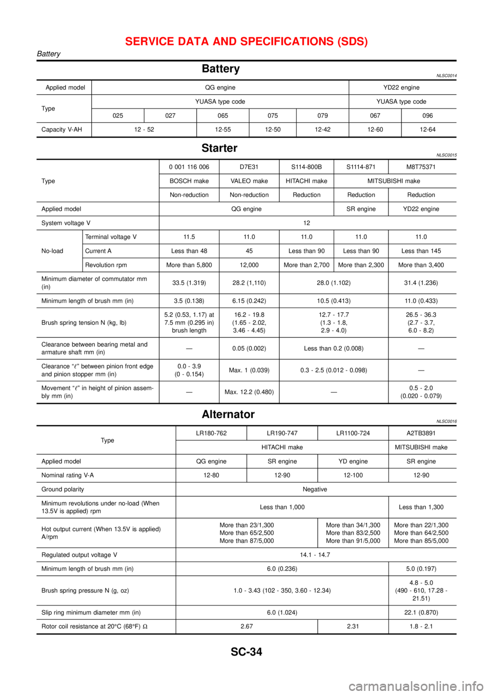
BatteryNLSC0014
Applied model QG engine YD22 engine
TypeYUASA type code YUASA type code
025 027 065 075 079 067 096
Capacity V-AH 12 - 52 12-55 12-50 12-42 12-60 12-64
StarterNLSC0015
Type0 001 116 006 D7E31 S114-800B S1114-871 M8T75371
BOSCH make VALEO make HITACHI make MITSUBISHI make
Non-reduction Non-reduction Reduction Reduction Reduction
Applied model QG engine SR engine YD22 engine
System voltage V12
No-loadTerminal voltage V 11.5 11.0 11.0 11.0 11.0
Current A Less than 48 45 Less than 90 Less than 90 Less than 145
Revolution rpm More than 5,800 12,000 More than 2,700 More than 2,300 More than 3,400
Minimum diameter of commutator mm
(in)33.5 (1.319) 28.2 (1,110) 28.0 (1.102) 31.4 (1.236)
Minimum length of brush mm (in) 3.5 (0.138) 6.15 (0.242) 10.5 (0.413) 11.0 (0.433)
Brush spring tension N (kg, lb)5.2 (0.53, 1.17) at
7.5 mm (0.295 in)
brush length16.2 - 19.8
(1.65 - 2.02,
3.46 - 4.45)12.7 - 17.7
(1.3 - 1.8,
2.9 - 4.0)26.5 - 36.3
(2.7 - 3.7,
6.0 - 8.2)
Clearance between bearing metal and
armature shaft mm (in)—0.05 (0.002) Less than 0.2 (0.008)—
Clearance“!”between pinion front edge
and pinion stopper mm (in)0.0 - 3.9
(0 - 0.154)Max. 1 (0.039) 0.3 - 2.5 (0.012 - 0.098)—
Movement“!”in height of pinion assem-
bly mm (in)—Max. 12.2 (0.480)—0.5 - 2.0
(0.020 - 0.079)
AlternatorNLSC0016
TypeLR180-762 LR190-747 LR1100-724 A2TB3891
HITACHI make MITSUBISHI make
Applied model QG engine SR engine YD engine SR engine
Nominal rating V-A 12-80 12-90 12-100 12-90
Ground polarityNegative
Minimum revolutions under no-load (When
13.5V is applied) rpmLess than 1,000 Less than 1,300
Hot output current (When 13.5V is applied)
A/rpmMore than 23/1,300
More than 65/2,500
More than 87/5,000More than 34/1,300
More than 83/2,500
More than 91/5,000More than 22/1,300
More than 64/2,500
More than 85/5,000
Regulated output voltage V 14.1 - 14.7
Minimum length of brush mm (in) 6.0 (0.236) 5.0 (0.197)
Brush spring pressure N (g, oz) 1.0 - 3.43 (102 - 350, 3.60 - 12.34)4.8 - 5.0
(490 - 610, 17.28 -
21.51)
Slip ring minimum diameter mm (in) 6.0 (1.024) 22.1 (0.870)
Rotor coil resistance at 20°C (68°F)Ω2.67 2.31 1.8 - 2.1
SERVICE DATA AND SPECIFICATIONS (SDS)
Battery
SC-34
Page 3003 of 3051
Bleeding Hydraulic SystemNLST00141. Raise front end of vehicle until wheels are clear of the ground.
2. Add fluid into oil tank to specified level. Then quickly turn steer-
ing wheel fully to right and left and lightly touch steering stop-
pers.
Repeat steering wheel operation until fluid level no longer
decreases.
3. Start engine.
Repeat step 2. above.
+Incomplete air bleeding will cause the following to occur. When
this happens, bleed air again.
a) Air bubbles in reservoir tank
b) Clicking noise in oil pump
c) Excessive buzzing in oil pump
Fluid noise may occur in the valve or oil pump. This is common
when the vehicle is stationary or while turning the steering wheel
slowly. This does not affect the performance or durability of the
system.
SST491B
SST090B
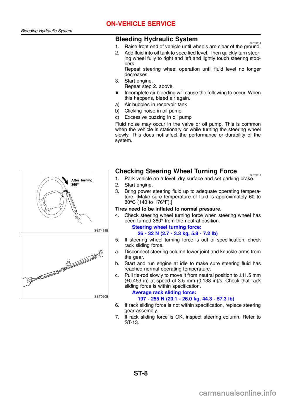
Checking Steering Wheel Turning ForceNLST00151. Park vehicle on a level, dry surface and set parking brake.
2. Start engine.
3. Bring power steering fluid up to adequate operating tempera-
ture. [Make sure temperature of fluid is approximately 60 to
80°C (140 to 176°F).]
Tires need to be inflated to normal pressure.
4. Check steering wheel turning force when steering wheel has
been turned 360°from the neutral position.
Steering wheel turning force:
26 - 32 N (2.7 - 3.3 kg, 5.8 - 7.2 lb)
5. If steering wheel turning force is out of specification, check
rack sliding force.
a. Disconnect steering column lower joint and knuckle arms from
the gear.
b. Start and run engine at idle to make sure steering fluid has
reached normal operating temperature.
c. Pull tie-rod slowly to move it from neutral position to±11.5 mm
(±0.453 in) at speed of 3.5 mm (0.138 in)/s. Check that rack
sliding force is within specification.
Average rack sliding force:
197 - 255 N (20.1 - 26.0 kg, 44.3 - 57.3 lb)
6. If rack sliding force is not within specification, replace steering
gear assembly.
7. If rack sliding force is OK, inspect steering column. Refer to
ST-13.
ON-VEHICLE SERVICE
Bleeding Hydraulic System
ST-8