2001 NISSAN ALMERA TINO stop start
[x] Cancel search: stop startPage 1551 of 3051
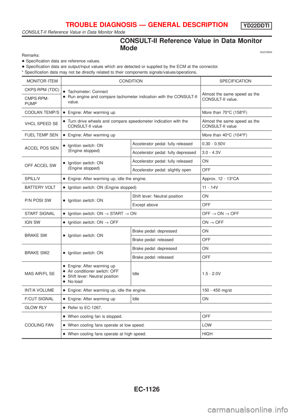
CONSULT-II Reference Value in Data Monitor
Mode
NLEC0634Remarks:
+Specification data are reference values.
+Specification data are output/input values which are detected or supplied by the ECM at the connector.
* Specification data may not be directly related to their components signals/values/operations.
MONITOR ITEM CONDITION SPECIFICATION
CKPS´RPM (TDC)
+Tachometer: Connect
+Run engine and compare tachometer indication with the CONSULT-II
value.Almost the same speed as the
CONSULT-II value. CMPS´RPM-
PUMP
COOLAN TEMP/S+Engine: After warming up More than 70ÉC (158ÉF)
VHCL SPEED SE+Turn drive wheels and compare speedometer indication with the
CONSULT-II valueAlmost the same speed as the
CONSULT-II value
FUEL TEMP SEN+Engine: After warming up More than 40ÉC (104ÉF)
ACCEL POS SEN+Ignition switch: ON
(Engine stopped)Accelerator pedal: fully released 0.30 - 0.50V
Accelerator pedal: fully depressed 3.0 - 4.3V
OFF ACCEL SW+Ignition switch: ON
(Engine stopped)Accelerator pedal: fully released ON
Accelerator pedal: slightly open OFF
SPILL/V+Engine: After warming up, idle the engine. Approx. 12 - 13ÉCA
BATTERY VOLT+Ignition switch: ON (Engine stopped) 11 - 14V
P/N POSI SW+Ignition switch: ONShift lever: Neutral position ON
Except above OFF
START SIGNAL+Ignition switch: ON®START®ON OFF®ON®OFF
IGN SW+Ignition switch: ON®OFF ON®OFF
BRAKE SW+Ignition switch: ONBrake pedal: depressed ON
Brake pedal: released OFF
BRAKE SW2+Ignition switch: ONBrake pedal: depressed ON
Brake pedal: released OFF
MAS AIR/FL SE+Engine: After warming up
+Air conditioner switch: OFF
+Shift lever: Neutral position
+No-loadIdle 1.5 - 2.0V
INT/A VOLUME+Engine: After warming up, idle the engine. 150 - 450 mg/st
F/CUT SIGNAL+Engine: After warming up Idle ON
GLOW RLY+Refer to EC-1267.
COOLING FAN+When cooling fan is stopped. OFF
+When cooling fans operate at low speed. LOW
+When cooling fans operate at high speed. HIGH
TROUBLE DIAGNOSIS Ð GENERAL DESCRIPTIONYD22DDTI
CONSULT-II Reference Value in Data Monitor Mode
EC-1126
Page 1702 of 3051
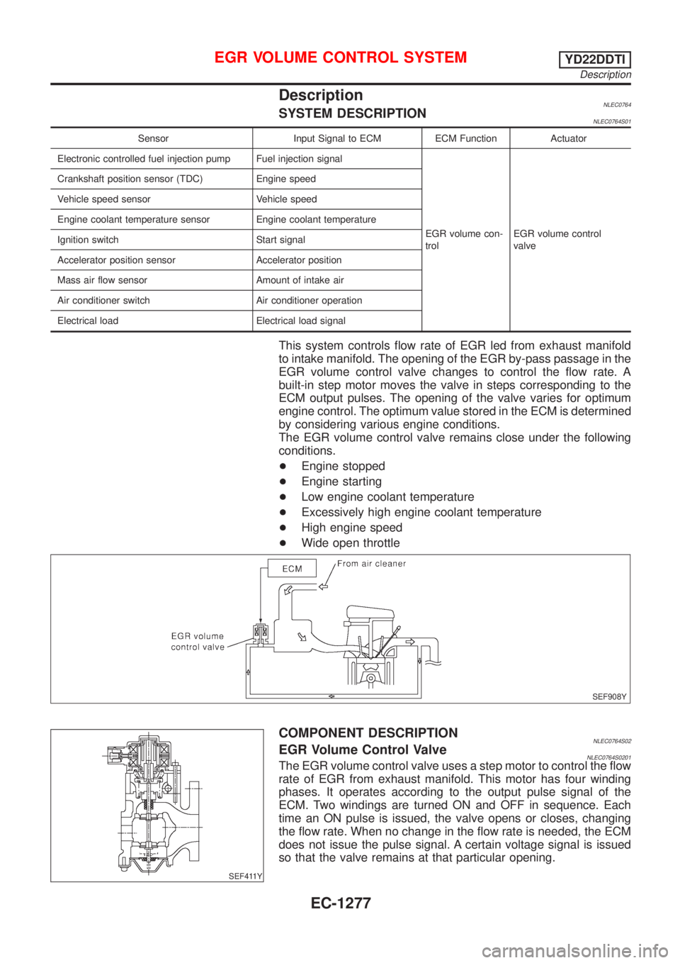
DescriptionNLEC0764SYSTEM DESCRIPTIONNLEC0764S01
Sensor Input Signal to ECM ECM Function Actuator
Electronic controlled fuel injection pump Fuel injection signal
EGR volume con-
trolEGR volume control
valve Crankshaft position sensor (TDC) Engine speed
Vehicle speed sensor Vehicle speed
Engine coolant temperature sensor Engine coolant temperature
Ignition switch Start signal
Accelerator position sensor Accelerator position
Mass air flow sensor Amount of intake air
Air conditioner switch Air conditioner operation
Electrical load Electrical load signal
This system controls flow rate of EGR led from exhaust manifold
to intake manifold. The opening of the EGR by-pass passage in the
EGR volume control valve changes to control the flow rate. A
built-in step motor moves the valve in steps corresponding to the
ECM output pulses. The opening of the valve varies for optimum
engine control. The optimum value stored in the ECM is determined
by considering various engine conditions.
The EGR volume control valve remains close under the following
conditions.
+Engine stopped
+Engine starting
+Low engine coolant temperature
+Excessively high engine coolant temperature
+High engine speed
+Wide open throttle
SEF908Y
SEF411Y
COMPONENT DESCRIPTIONNLEC0764S02EGR Volume Control ValveNLEC0764S0201The EGR volume control valve uses a step motor to control the flow
rate of EGR from exhaust manifold. This motor has four winding
phases. It operates according to the output pulse signal of the
ECM. Two windings are turned ON and OFF in sequence. Each
time an ON pulse is issued, the valve opens or closes, changing
the flow rate. When no change in the flow rate is needed, the ECM
does not issue the pulse signal. A certain voltage signal is issued
so that the valve remains at that particular opening.
EGR VOLUME CONTROL SYSTEMYD22DDTI
Description
EC-1277
Page 1812 of 3051
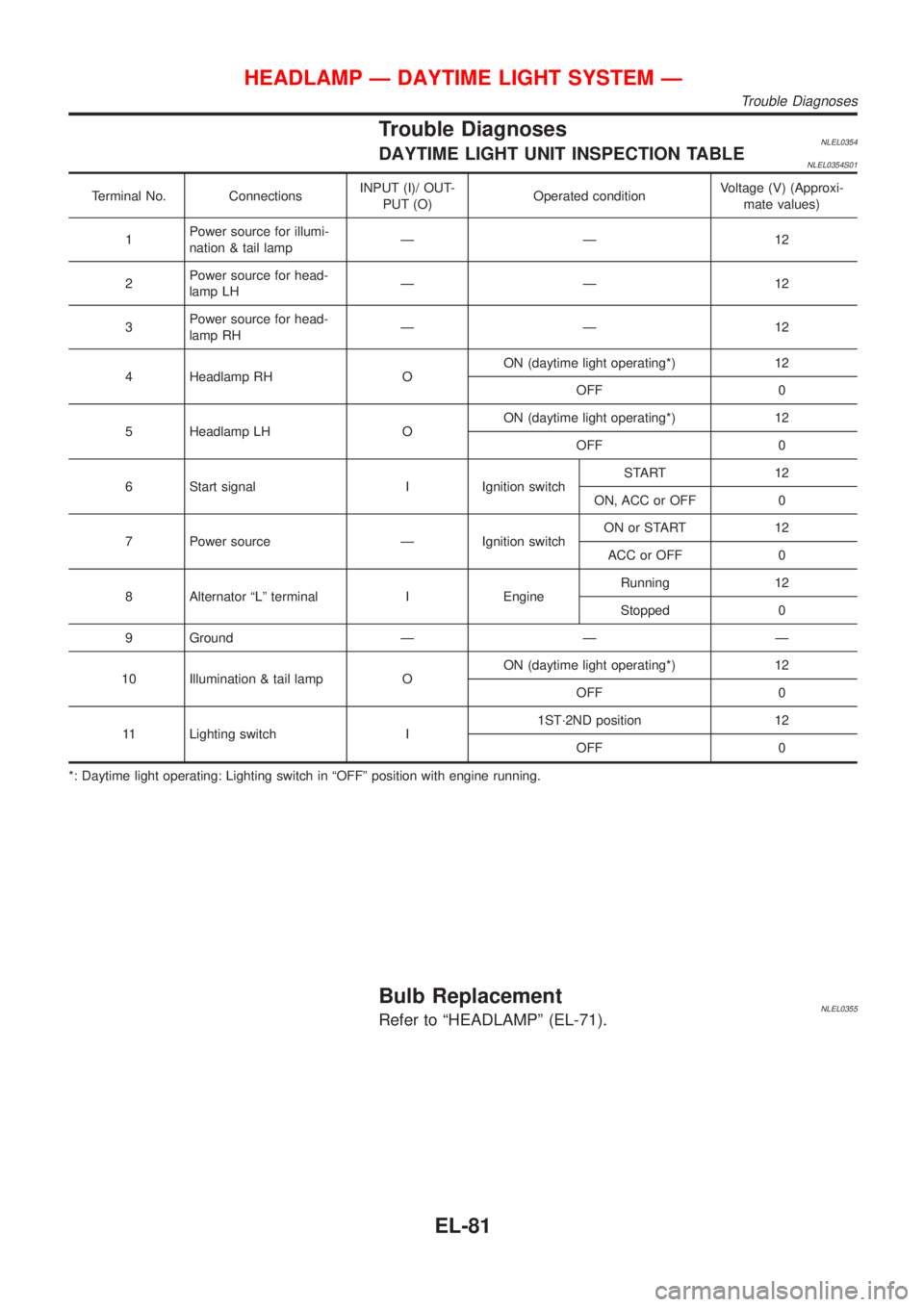
Trouble DiagnosesNLEL0354DAYTIME LIGHT UNIT INSPECTION TABLENLEL0354S01
Terminal No. ConnectionsINPUT (I)/ OUT-
PUT (O)Operated conditionVoltage (V) (Approxi-
mate values)
1Power source for illumi-
nation & tail lampÐÐ 12
2Power source for head-
lamp LHÐÐ 12
3Power source for head-
lamp RHÐÐ 12
4 Headlamp RH OON (daytime light operating*) 12
OFF 0
5 Headlamp LH OON (daytime light operating*) 12
OFF 0
6 Start signal I Ignition switchSTART 12
ON, ACC or OFF 0
7 Power source Ð Ignition switchON or START 12
ACC or OFF 0
8 Alternator ªLº terminal I EngineRunning 12
Stopped 0
9 Ground Ð Ð Ð
10 Illumination & tail lamp OON (daytime light operating*) 12
OFF 0
11 Lighting switch I1ST´2ND position 12
OFF 0
*: Daytime light operating: Lighting switch in ªOFFº position with engine running.
Bulb ReplacementNLEL0355Refer to ªHEADLAMPº (EL-71).
HEADLAMP Ð DAYTIME LIGHT SYSTEM Ð
Trouble Diagnoses
EL-81
Page 1907 of 3051
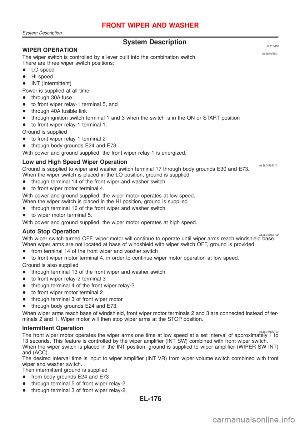
System DescriptionNLEL0456WIPER OPERATIONNLEL0456S01The wiper switch is controlled by a lever built into the combination switch.
There are three wiper switch positions:
+LO speed
+HI speed
+INT (Intermittent)
Power is supplied at all time
+through 30A fuse
+to front wiper relay-1 terminal 5, and
+through 40A fusible link
+through ignition switch terminal 1 and 3 when the switch is in the ON or START position
+to front wiper relay-1 terminal 1.
Ground is supplied
+to front wiper relay-1 terminal 2
+through body grounds E24 and E73
With power and ground supplied, the front wiper relay-1 is energized.
Low and High Speed Wiper OperationNLEL0456S0101Ground is supplied to wiper and washer switch terminal 17 through body grounds E30 and E73.
When the wiper switch is placed in the LO position, ground is supplied
+through terminal 14 of the front wiper and washer switch
+to front wiper motor terminal 4.
With power and ground supplied, the wiper motor operates at low speed.
When the wiper switch is placed in the HI position, ground is supplied
+through terminal 16 of the front wiper and washer switch
+to wiper motor terminal 5.
With power and ground supplied, the wiper motor operates at high speed.
Auto Stop OperationNLEL0456S0102With wiper switch turned OFF, wiper motor will continue to operate until wiper arms reach windshield base.
When wiper arms are not located at base of windshield with wiper switch OFF, ground is provided
+from terminal 14 of the front wiper and washer switch
+to front wiper motor terminal 4, in order to continue wiper motor operation at low speed.
Ground is also supplied
+through terminal 13 of the front wiper and washer switch
+to front wiper relay-2 terminal 3
+through terminal 4 of the front wiper relay-2.
+to front wiper motor terminal 2
+through terminal 3 of front wiper motor
+through body grounds E24 and E73.
When wiper arms reach base of windshield, front wiper motor terminals 2 and 3 are connected instead of ter-
minals 2 and 1. Wiper motor will then stop wiper arms at the STOP position.
Intermittent OperationNLEL0456S0103The front wiper motor operates the wiper arms one time at low speed at a set interval of approximately 1 to
13 seconds. This feature is controlled by the wiper amplifier (INT SW) combined with front wiper switch.
When the wiper switch is placed in the INT position, ground is supplied to wiper amplifier (WIPER SW INT)
and (ACC).
The desired interval time is input to wiper amplifier (INT VR) from wiper volume switch combined with front
wiper and washer switch.
Then intermittent ground is supplied
+from body grounds E24 and E73
+through terminal 5 of front wiper relay-2,
+through terminal 3 of front wiper relay-2,
FRONT WIPER AND WASHER
System Description
EL-176
Page 2147 of 3051
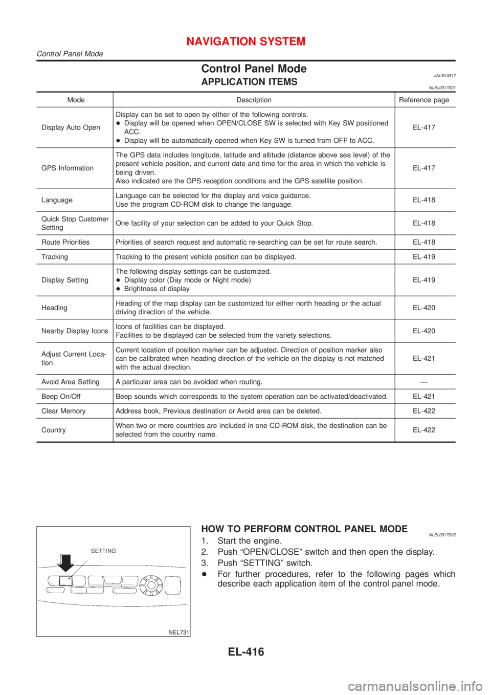
Control Panel Mode=NLEL0517APPLICATION ITEMSNLEL0517S01
Mode Description Reference page
Display Auto OpenDisplay can be set to open by either of the following controls.
+Display will be opened when OPEN/CLOSE SW is selected with Key SW positioned
ACC.
+Display will be automatically opened when Key SW is turned from OFF to ACC.EL-417
GPS InformationThe GPS data includes longitude, latitude and altitude (distance above sea level) of the
present vehicle position, and current date and time for the area in which the vehicle is
being driven.
Also indicated are the GPS reception conditions and the GPS satellite position.EL-417
LanguageLanguage can be selected for the display and voice guidance.
Use the program CD-ROM disk to change the language.EL-418
Quick Stop Customer
SettingOne facility of your selection can be added to your Quick Stop. EL-418
Route Priorities Priorities of search request and automatic re-searching can be set for route search. EL-418
Tracking Tracking to the present vehicle position can be displayed. EL-419
Display SettingThe following display settings can be customized.
+Display color (Day mode or Night mode)
+Brightness of displayEL-419
HeadingHeading of the map display can be customized for either north heading or the actual
driving direction of the vehicle.EL-420
Nearby Display IconsIcons of facilities can be displayed.
Facilities to be displayed can be selected from the variety selections.EL-420
Adjust Current Loca-
tionCurrent location of position marker can be adjusted. Direction of position marker also
can be calibrated when heading direction of the vehicle on the display is not matched
with the actual direction.EL-421
Avoid Area Setting A particular area can be avoided when routing. Ð
Beep On/Off Beep sounds which corresponds to the system operation can be activated/deactivated. EL-421
Clear Memory Address book, Previous destination or Avoid area can be deleted. EL-422
CountryWhen two or more countries are included in one CD-ROM disk, the destination can be
selected from the country name.EL-422
NEL731
HOW TO PERFORM CONTROL PANEL MODENLEL0517S021. Start the engine.
2. Push ªOPEN/CLOSEº switch and then open the display.
3. Push ªSETTINGº switch.
+For further procedures, refer to the following pages which
describe each application item of the control panel mode.
NAVIGATION SYSTEM
Control Panel Mode
EL-416
Page 2149 of 3051
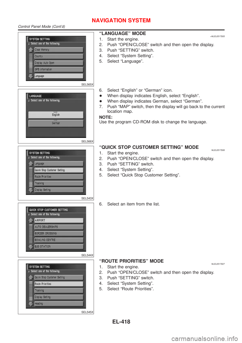
SEL565X
ªLANGUAGEº MODE=NLEL0517S051. Start the engine.
2. Push ªOPEN/CLOSEº switch and then open the display.
3. Push ªSETTINGº switch.
4. Select ªSystem Settingº.
5. Select ªLanguageº.
SEL566X
6. Select ªEnglishº or ªGermanº icon.
+When display indicates English, select ªEnglishº.
+When display indicates German, select ªGermanº.
7. Push ªMAPº switch, then the display will go back to the current
location map.
NOTE:
Use the program CD-ROM disk to change the language.
SEL543X
ªQUICK STOP CUSTOMER SETTINGº MODENLEL0517S061. Start the engine.
2. Push ªOPEN/CLOSEº switch and then open the display.
3. Push ªSETTINGº switch.
4. Select ªSystem Settingº.
5. Select ªQuick Stop Customer Settingº.
SEL544X
6. Select an item from the list.
SEL545X
ªROUTE PRIORITIESº MODENLEL0517S071. Start the engine.
2. Push ªOPEN/CLOSEº switch and then open the display.
3. Push ªSETTINGº switch.
4. Select ªSystem Settingº.
5. Select ªRoute Prioritiesº.
NAVIGATION SYSTEM
Control Panel Mode (Cont'd)
EL-418
Page 2166 of 3051
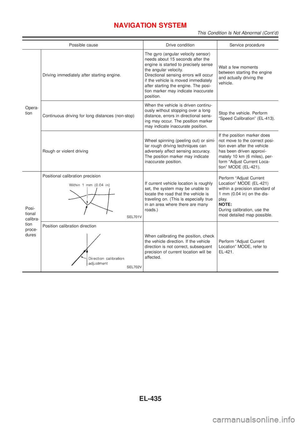
Possible cause Drive condition Service procedure
Opera-
tionDriving immediately after starting engine.The gyro (angular velocity sensor)
needs about 15 seconds after the
engine is started to precisely sense
the angular velocity.
Directional sensing errors will occur
if the vehicle is moved immediately
after starting the engine. The posi-
tion marker may indicate inaccurate
position.Wait a few moments
between starting the engine
and actually driving the
vehicle.
Continuous driving for long distances (non-stop)When the vehicle is driven continu-
ously without stopping over a long
distance, errors in directional sens-
ing may occur. The position marker
may indicate inaccurate position.Stop the vehicle. Perform
ªSpeed Calibrationº (EL-413).
Rough or violent drivingWheel spinning (peeling out) or simi-
lar rough driving techniques can
adversely affect sensing accuracy.
The position marker may indicate
inaccurate position.If the position marker does
not move to the correct posi-
tion even after the vehicle
has been driven approxi-
mately 10 km (6 miles), per-
form ªAdjust Current Loca-
tionº MODE (EL-421).
Posi-
tional
calibra-
tion
proce-
duresPositional calibration precision
SEL701V
If current vehicle location is roughly
set, the system may be unable to
locate the road that the vehicle is
traveling on. (This is especially true
in an area where there are many
roads.)Perform ªAdjust Current
Locationº MODE (EL-421)
within a precision standard of
1 mm (0.04 in) on the dis-
play.
NOTE:
During calibration, use the
most detailed map possible.
Position calibration direction
SEL702V
When calibrating the position, check
the vehicle direction. If the vehicle
direction is not correct, subsequent
precision of current location will be
affected.Perform ªAdjust Current
Locationº MODE, refer to
EL-421.
NAVIGATION SYSTEM
This Condition Is Not Abnormal (Cont'd)
EL-435
Page 2257 of 3051
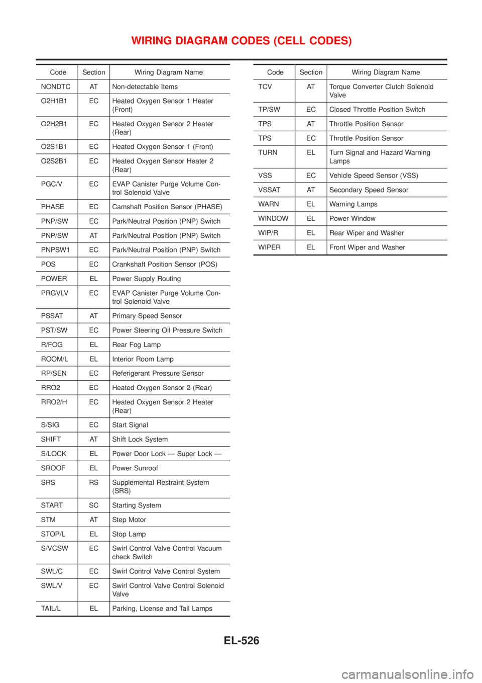
Code Section Wiring Diagram Name
NONDTC AT Non-detectable Items
O2H1B1 EC Heated Oxygen Sensor 1 Heater
(Front)
O2H2B1 EC Heated Oxygen Sensor 2 Heater
(Rear)
O2S1B1 EC Heated Oxygen Sensor 1 (Front)
O2S2B1 EC Heated Oxygen Sensor Heater 2
(Rear)
PGC/V EC EVAP Canister Purge Volume Con-
trol Solenoid Valve
PHASE EC Camshaft Position Sensor (PHASE)
PNP/SW EC Park/Neutral Position (PNP) Switch
PNP/SW AT Park/Neutral Position (PNP) Switch
PNPSW1 EC Park/Neutral Position (PNP) Switch
POS EC Crankshaft Position Sensor (POS)
POWER EL Power Supply Routing
PRGVLV EC EVAP Canister Purge Volume Con-
trol Solenoid Valve
PSSAT AT Primary Speed Sensor
PST/SW EC Power Steering Oil Pressure Switch
R/FOG EL Rear Fog Lamp
ROOM/L EL Interior Room Lamp
RP/SEN EC Referigerant Pressure Sensor
RRO2 EC Heated Oxygen Sensor 2 (Rear)
RRO2/H EC Heated Oxygen Sensor 2 Heater
(Rear)
S/SIG EC Start Signal
SHIFT AT Shift Lock System
S/LOCK EL Power Door Lock Ð Super Lock Ð
SROOF EL Power Sunroof
SRS RS Supplemental Restraint System
(SRS)
START SC Starting System
STM AT Step Motor
STOP/L EL Stop Lamp
S/VCSW EC Swirl Control Valve Control Vacuum
check Switch
SWL/C EC Swirl Control Valve Control System
SWL/V EC Swirl Control Valve Control Solenoid
Valve
TAIL/L EL Parking, License and Tail LampsCode Section Wiring Diagram Name
TCV AT Torque Converter Clutch Solenoid
Valve
TP/SW EC Closed Throttle Position Switch
TPS AT Throttle Position Sensor
TPS EC Throttle Position Sensor
TURN EL Turn Signal and Hazard Warning
Lamps
VSS EC Vehicle Speed Sensor (VSS)
VSSAT AT Secondary Speed Sensor
WARN EL Warning Lamps
WINDOW EL Power Window
WIP/R EL Rear Wiper and Washer
WIPER EL Front Wiper and Washer
WIRING DIAGRAM CODES (CELL CODES)
EL-526