Page 47 of 3051
SAT631IA
SAT632I
SEF234G
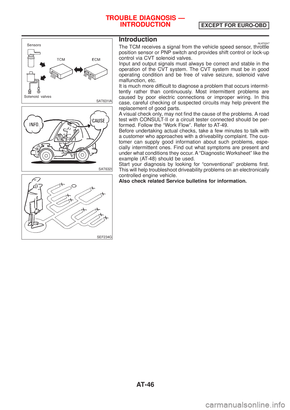
IntroductionNLAT0247The TCM receives a signal from the vehicle speed sensor, throttle
position sensor or PNP switch and provides shift control or lock-up
control via CVT solenoid valves.
Input and output signals must always be correct and stable in the
operation of the CVT system. The CVT system must be in good
operating condition and be free of valve seizure, solenoid valve
malfunction, etc.
It is much more difficult to diagnose a problem that occurs intermit-
tently rather than continuously. Most intermittent problems are
caused by poor electric connections or improper wiring. In this
case, careful checking of suspected circuits may help prevent the
replacement of good parts.
A visual check only, may not find the cause of the problems. A road
test with CONSULT-II or a circuit tester connected should be per-
formed. Follow the ªWork Flowº. Refer to AT-49.
Before undertaking actual checks, take a few minutes to talk with
a customer who approaches with a driveability complaint. The cus-
tomer can supply good information about such problems, espe-
cially intermittent ones. Find out what symptoms are present and
under what conditions they occur. A ªDiagnostic Worksheetº like the
example (AT-48) should be used.
Start your diagnosis by looking for ªconventionalº problems first.
This will help troubleshoot driveability problems on an electronically
controlled engine vehicle.
Also check related Service bulletins for information.
TROUBLE DIAGNOSIS Ð
INTRODUCTION
EXCEPT FOR EURO-OBD
AT-46
Page 48 of 3051
DIAGNOSTIC WORKSHEET=NLAT0247S01Information from CustomerNLAT0247S0101KEY POINTS
WHAT..... Vehicle & CVT model
WHEN..... Date, Frequencies
WHERE..... Road conditions
HOW..... Operating conditions, Symptoms
Customer name MR/MS Model & Year VIN
Trans. model Engine Mileage
Incident Date Manuf. Date In Service Date
FrequencyNContinuousNIntermittent ( times a day)
NVehicle does not move. (NAny positionNParticular position)
SymptomsNLockup malfunction
NShift point too high or too low.
NShift shock or slip (NN®DNLockupNAny drive position)
NNoise or vibration
NNo pattern select
NOthers
()
SPORT indicator lamp Blinks for about 8 seconds.
NContinuously litNNot lit
TROUBLE DIAGNOSIS Ð
INTRODUCTION
EXCEPT FOR EURO-OBD
Introduction (Cont'd)
AT-47
Page 199 of 3051
Diagnostic ProcedureNLAT0319SYMPTOM 1:
+Selector lever cannot be moved from ªPº position with key
in ON position and brake pedal applied.
+Selector lever can be moved from ªPº position with key in
ON position and brake pedal released.
+Selector lever can be moved from ªPº position when key
is removed from key cylinder.
SYMPTOM 2:
Ignition key cannot be removed when selector lever is set to
ªPº position. It can be removed when selector lever is set to
any position except ªPº.
1 CHECK KEY INTERLOCK CABLE
Check key interlock cable for damage.
OK or NG
OK©GO TO 2.
NG©Repair key interlock cable. Refer to AT-202.
2 CHECK SELECTOR LEVER POSITION
Check selector lever position for damage.
OK or NG
OK©GO TO 3.
NG©Check selector lever. Refer to ªON-VEHICLE SERVICE Ð PNP Switch and Control
Cable Adjustmentº, AT-204.
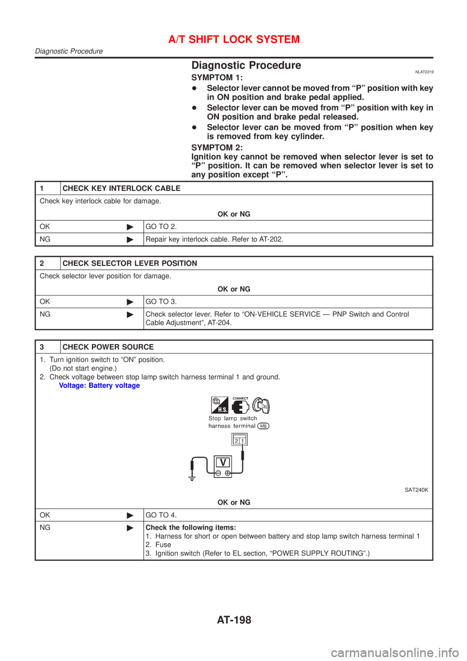
3 CHECK POWER SOURCE
1. Turn ignition switch to ªONº position.
(Do not start engine.)
2. Check voltage between stop lamp switch harness terminal 1 and ground.
Voltage: Battery voltage
SAT240K
OK or NG
OK©GO TO 4.
NG©Check the following items:
1. Harness for short or open between battery and stop lamp switch harness terminal 1
2. Fuse
3. Ignition switch (Refer to EL section, ªPOWER SUPPLY ROUTINGº.)
A/T SHIFT LOCK SYSTEM
Diagnostic Procedure
AT-198
Page 205 of 3051
SAT658J
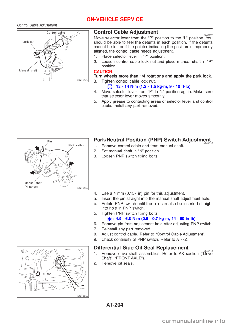
Control Cable AdjustmentNLAT0111Move selector lever from the ªPº position to the ªLº position. You
should be able to feel the detents in each position. If the detents
cannot be felt or if the pointer indicating the position is improperly
aligned, the control cable needs adjustment.
1. Place selector lever in ªPº position.
2. Loosen control cable lock nut and place manual shaft in ªPº
position.
CAUTION:
Turn wheels more than 1/4 rotations and apply the park lock.
3. Tighten control cable lock nut.
: 12 - 14 N´m (1.2 - 1.5 kg-m,9-10ft-lb)
4. Move selector lever from ªPº to ªLº position again. Make sure
that selector lever moves smoothly.
5. Apply grease to contacting areas of selector lever and control
cable. Install any part removed.
SAT659J
Park/Neutral Position (PNP) Switch AdjustmentNLAT01121. Remove control cable end from manual shaft.
2. Set manual shaft in ªNº position.
3. Loosen PNP switch fixing bolts.
4. Usea4mm(0.157 in) pin for this adjustment.
a. Insert the pin straight into the manual shaft adjustment hole.
b. Rotate PNP switch until the pin can also be inserted straight
into hole in PNP switch.
5. Tighten PNP switch fixing bolts.
: 4.9 - 6.8 N´m (0.5 - 0.7 kg-m, 44 - 60 in-lb)
6. Remove pin from adjustment hole after adjusting PNP switch.
7. Reinstall any part removed.
8. Adjust control cable. Refer to ªControl Cable Adjustmentº.
9. Check continuity of PNP switch. Refer to AT-72.
SAT660J
Differential Side Oil Seal ReplacementNLAT01131. Remove drive shaft assemblies. Refer to AX section (ªDrive
Shaftº, ªFRONT AXLEº).
2. Remove oil seals.
ON-VEHICLE SERVICE
Control Cable Adjustment
AT-204
Page 206 of 3051
SAT661JB
3. Install oil seals.
+Apply CVT fluid to oil seal surface before installing.
+Install oil seals so that dimensions ªAº and ªBº are within
specifications.
Unit: mm (in)
AB
5.5 - 6.5 (0.217 - 0.256) þ0.5 to 0.5 (þ0.020 to 0.020)
4. Reinstall any part removed.
ON-VEHICLE SERVICE
Differential Side Oil Seal Replacement (Cont'd)
AT-205
Page 211 of 3051
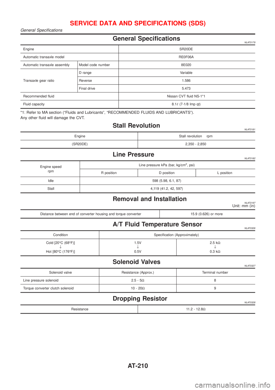
General SpecificationsNLAT0179
EngineSR20DE
Automatic transaxle modelRE0F06A
Automatic transaxle assembly Model code number 8E020
Transaxle gear ratioD range Variable
Reverse 1.586
Final drive 5.473
Recommended fluidNissan CVT fluid NS-1*1
Fluid capacity8.1!(7-1/8 Imp qt)
*1: Refer to MA section (ªFluids and Lubricantsº, ªRECOMMENDED FLUIDS AND LUBRICANTSº).
Any other fluid will damage the CVT.
Stall RevolutionNLAT0181
Engine Stall revolution rpm
(SR20DE) 2,350 - 2,850
Line PressureNLAT0182
Engine speed
rpmLine pressure kPa (bar, kg/cm2, psi)
R position D position L position
Idle 598 (5.98, 6.1, 87)
Stall 4,119 (41.2, 42, 597)
Removal and InstallationNLAT0197Unit: mm (in)
Distance between end of converter housing and torque converter 15.9 (0.626) or more
A/T Fluid Temperature SensorNLAT0326
Condition Specification (Approximately)
Cold [20ÉC (68ÉF)]
¯
Hot [80ÉC (176ÉF)]1.5V
¯
0.5V2.5 kW
¯
0.3 kW
Solenoid ValvesNLAT0327
Solenoid valve Resistance (Approx.) Terminal number
Line pressure solenoid 2.5 - 5W8
Torque converter clutch solenoid 10 - 20W9
Dropping ResistorNLAT0328
Resistance 11.2 - 12.8W
SERVICE DATA AND SPECIFICATIONS (SDS)
General Specifications
AT-210
Page 212 of 3051
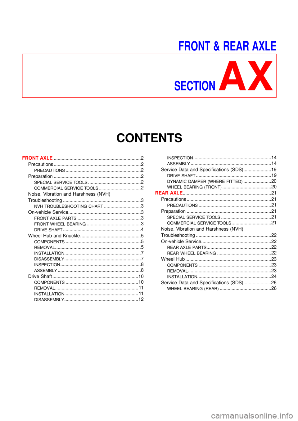
FRONT & REAR AXLE
SECTION
AX
CONTENTS
FRONT AXLE..................................................................2
Precautions ..................................................................2
PRECAUTIONS.........................................................2
Preparation ..................................................................2
SPECIAL SERVICE TOOLS........................................2
COMMERCIAL SERVICE TOOLS................................2
Noise, Vibration and Harshness (NVH)
Troubleshooting ...........................................................3
NVH TROUBLESHOOTING CHART............................3
On-vehicle Service.......................................................3
FRONT AXLE PARTS................................................3
FRONT WHEEL BEARING.........................................3
DRIVE SHAFT...........................................................4
Wheel Hub and Knuckle ..............................................5
COMPONENTS.........................................................5
REMOVAL.................................................................5
INSTALLATION..........................................................7
DISASSEMBLY..........................................................7
INSPECTION.............................................................8
ASSEMBLY...............................................................8
Drive Shaft .................................................................10
COMPONENTS.......................................................10
REMOVAL............................................................... 11
INSTALLATION........................................................ 11
DISASSEMBLY........................................................12
INSPECTION...........................................................14
ASSEMBLY.............................................................14
Service Data and Specifications (SDS).....................19
DRIVE SHAFT.........................................................19
DYNAMIC DAMPER (WHERE FITTED).....................20
WHEEL BEARING (FRONT).....................................20
REAR AXLE...................................................................21
Precautions ................................................................21
PRECAUTIONS.......................................................21
Preparation ................................................................21
SPECIAL SERVICE TOOLS......................................21
COMMERCIAL SERVICE TOOLS..............................21
Noise, Vibration and Harshness (NVH)
Troubleshooting .........................................................22
On-vehicle Service.....................................................22
REAR AXLE PARTS.................................................22
REAR WHEEL BEARING.........................................22
Wheel Hub .................................................................23
COMPONENTS.......................................................23
REMOVAL...............................................................23
INSTALLATION........................................................24
Service Data and Specifications (SDS).....................26
WHEEL BEARING (REAR).......................................26
Page 213 of 3051
SBR686C
Precautions
PRECAUTIONSNLAX0001+When installing rubber parts, final tightening must be car-
ried out under unladen condition* with tires on ground.
*: Fuel, radiator coolant and engine oil full. Spare tire, jack,
hand tools and mats in designated positions.
+After installing removed suspension parts, check wheel
alignment and adjust if necessary.
+Use flare nut wrench when removing or installing brake
tubes.
+Always torque brake lines when installing.
Preparation
SPECIAL SERVICE TOOLSNLAX0002
Tool number
Tool nameDescription
HT72520000
Ball joint remover
NT146
Removing tie-rod outer end and lower ball joint
KV38106800
Differential side oil seal
protector
NT147
Installing drive shaft
KV38106800
COMMERCIAL SERVICE TOOLSNLAX0003
Tool name Description
1 Flare nut crowfoot
2 Torque wrench
NT360
Removing and installing each brake piping
a: 10 mm (0.39 in)
FRONT AXLE
Precautions
AX-2