2001 NISSAN ALMERA TINO overheating
[x] Cancel search: overheatingPage 1233 of 3051
On Board Diagnosis LogicNLEC1752When a misfire occurs, engine speed will fluctuate (vary). If the engine speed fluctuates enough to cause the
CKP sensor to vary, ECM can detect a misfire.
Sensor Input Signal to ECM ECM function
Crankshaft position sensor (OBD) Engine speed On board diagnosis of misfire
The misfire detection logic consists of the following two conditions.
1. One Trip Detection Logic (Three Way Catalyst Damage)
On the first rip that a misfire condition occurs that can damage the three way catalyst (TWC) due to
overheating, the MI will blink.
When a misfire condition occurs, the ECM monitors the CKP sensor (OBD) signal every 200 engine revo-
lutions for a change.
When the misfire condition decreases to a level that will not damage the TWC, the MI will turn off.
If another misfire condition occurs that can damage the TWC on a second trip, the MI will blink.
When the misfire condition decreases to a level that will not damage the TWC, the MI will remain on.
If another misfire condition occurs that can damage the TWC, the MI will begin to blink again.
2. Two Trip Detection Logic (Exhaust quality deterioration)
For misfire conditions that will not cause damage to the TWC (but will affect vehicle emissions), the MI
will only light when the misfire is detected on a second trip. During this condition, the ECM monitors the
CKP sensor (OBD) signal every 1,000 engine revolutions.
A misfire malfunction can be detected on any one cylinder or on-multiple cylinders.
DTC No. Malfunction is detected when ... Check Items (Possible Cause)
P0300+Multiple cylinders misfire.+Improper spark plug
+Insufficient compression
+Incorrect fuel pressure
+EGR volume control valve
+The injector circuit is open or shorted
+Injectors
+Intake air leak
+The ignition secondary circuit is open or shorted
+Lack of fuel
+Drive plate
+Heated oxygen sensor 1 (front)
+Incorrect distributor roter P0301+No. 1 cylinder misfires.
P0302+No. 2 cylinder misfires.
P0303+No. 3 cylinder misfires.
P0304+No. 4 cylinder misfires.
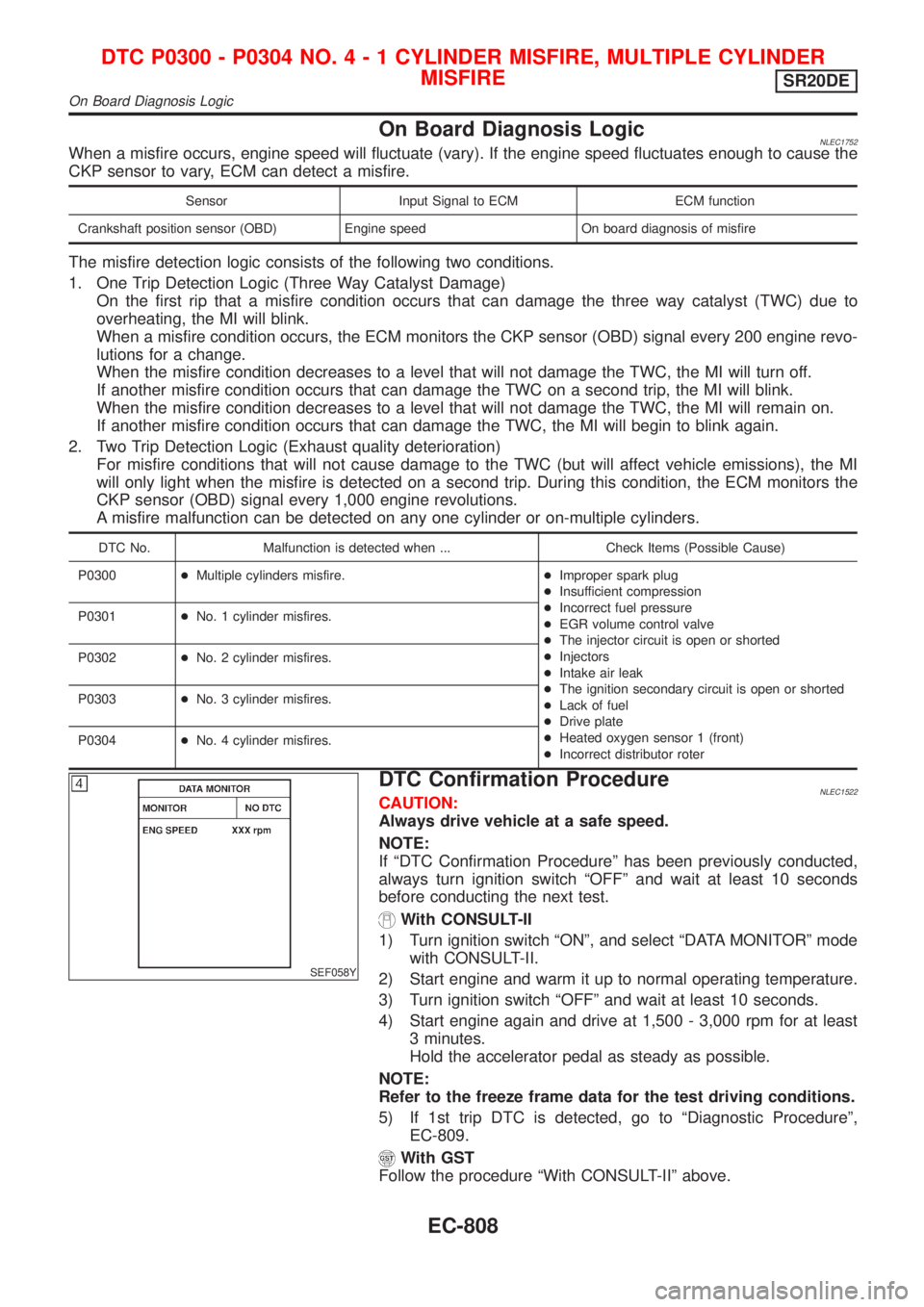
SEF058Y
DTC Confirmation ProcedureNLEC1522CAUTION:
Always drive vehicle at a safe speed.
NOTE:
If ªDTC Confirmation Procedureº has been previously conducted,
always turn ignition switch ªOFFº and wait at least 10 seconds
before conducting the next test.
With CONSULT-II
1) Turn ignition switch ªONº, and select ªDATA MONITORº mode
with CONSULT-II.
2) Start engine and warm it up to normal operating temperature.
3) Turn ignition switch ªOFFº and wait at least 10 seconds.
4) Start engine again and drive at 1,500 - 3,000 rpm for at least
3 minutes.
Hold the accelerator pedal as steady as possible.
NOTE:
Refer to the freeze frame data for the test driving conditions.
5) If 1st trip DTC is detected, go to ªDiagnostic Procedureº,
EC-809.
With GST
Follow the procedure ªWith CONSULT-IIº above.
DTC P0300 - P0304 NO.4-1CYLINDER MISFIRE, MULTIPLE CYLINDER
MISFIRE
SR20DE
On Board Diagnosis Logic
EC-808
Page 1308 of 3051
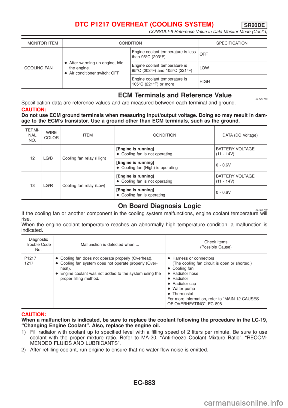
MONITOR ITEM CONDITION SPECIFICATION
COOLING FAN+After warming up engine, idle
the engine.
+Air conditioner switch: OFFEngine coolant temperature is less
than 95ÉC (203ÉF)OFF
Engine coolant temperature is
95ÉC (203ÉF) and 105ÉC (221ÉF)LOW
Engine coolant temperature is
105ÉC (221ÉF) or moreHIGH
ECM Terminals and Reference ValueNLEC1769Specification data are reference values and are measured between each terminal and ground.
CAUTION:
Do not use ECM ground terminals when measuring input/output voltage. Doing so may result in dam-
age to the ECM's transistor. Use a ground other than ECM terminals, such as the ground.
TERMI-
NAL
NO.WIRE
COLORITEM CONDITION DATA (DC Voltage)
12 LG/B Cooling fan relay (High)[Engine is running]
+Cooling fan is not operatingBATTERY VOLTAGE
(11 - 14V)
[Engine is running]
+Cooling fan (High) is operating0 - 0.6V
13 LG/R Cooling fan relay (Low)[Engine is running]
+Cooling fan is not operatingBATTERY VOLTAGE
(11 - 14V)
[Engine is running]
+Cooling fan is operating0 - 0.6V
On Board Diagnosis LogicNLEC1770If the cooling fan or another component in the cooling system malfunctions, engine coolant temperature will
rise.
When the engine coolant temperature reaches an abnormally high temperature condition, a malfunction is
indicated.
Diagnostic
Trouble Code
No.Malfunction is detected when ...Check Items
(Possible Cause)
P1217
1217+Cooling fan does not operate properly (Overheat).
+Cooling fan system does not operate properly (Over-
heat).
+Engine coolant was not added to the system using the
proper filling method.+Harness or connectors
(The cooling fan circuit is open or shorted.)
+Cooling fan
+Radiator hose
+Radiator
+Radiator cap
+Water pump
+Thermostat
For more information, refer to ªMAIN 12 CAUSES
OF OVERHEATINGº, EC-898.
CAUTION:
When a malfunction is indicated, be sure to replace the coolant following the procedure in the LC-19,
ªChanging Engine Coolantº. Also, replace the engine oil.
1) Fill radiator with coolant up to specified level with a filling speed of 2 liters per minute. Be sure to use
coolant with the proper mixture ratio. Refer to MA-20, ªAnti-freeze Coolant Mixture Ratioº, ªRECOM-
MENDED FLUIDS AND LUBRICANTSº.
2) After refilling coolant, run engine to ensure that no water-flow noise is emitted.
DTC P1217 OVERHEAT (COOLING SYSTEM)SR20DE
CONSULT-II Reference Value in Data Monitor Mode (Cont'd)
EC-883
Page 1316 of 3051
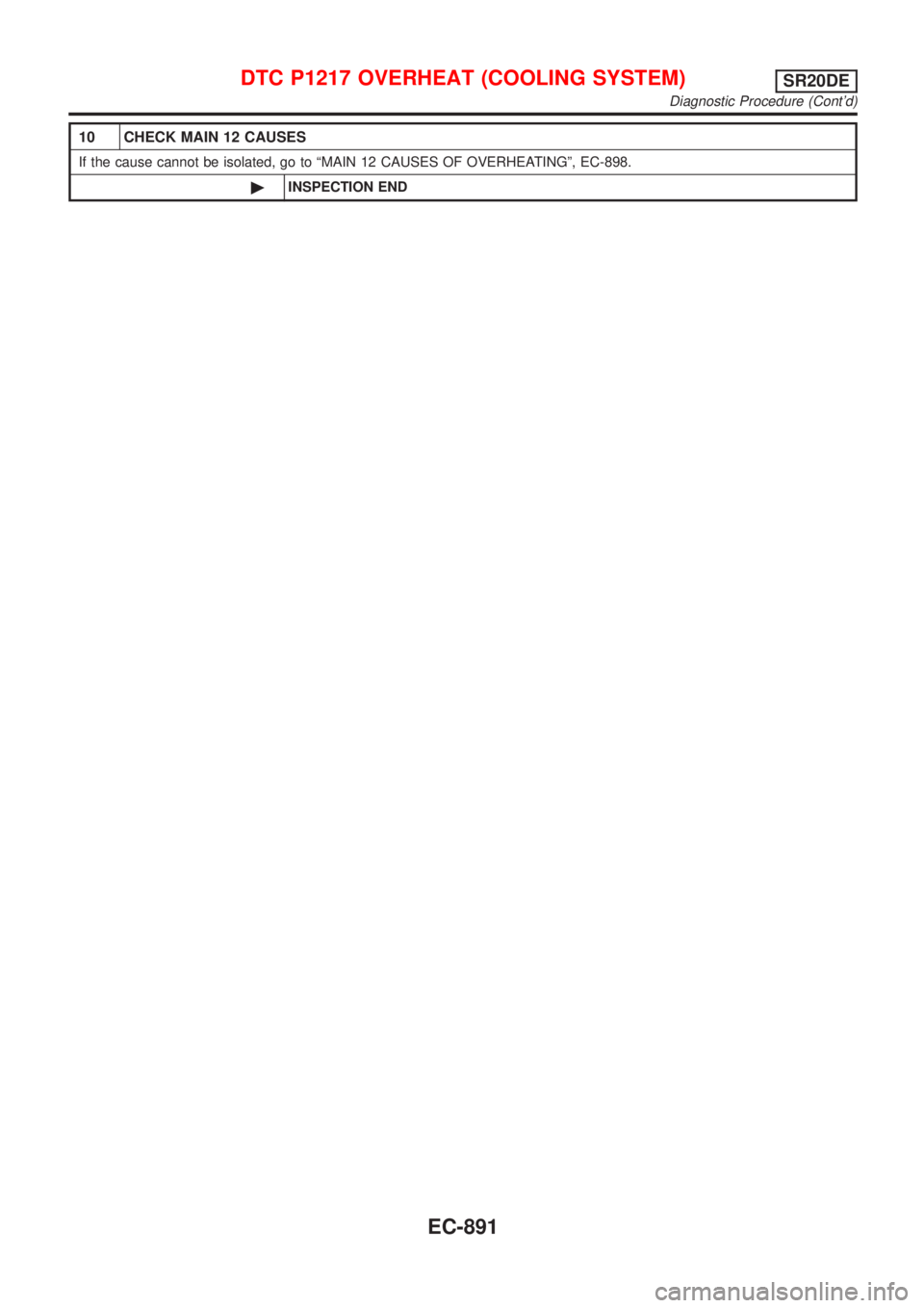
10 CHECK MAIN 12 CAUSES
If the cause cannot be isolated, go to ªMAIN 12 CAUSES OF OVERHEATINGº, EC-898.
©INSPECTION END
DTC P1217 OVERHEAT (COOLING SYSTEM)SR20DE
Diagnostic Procedure (Cont'd)
EC-891
Page 1323 of 3051
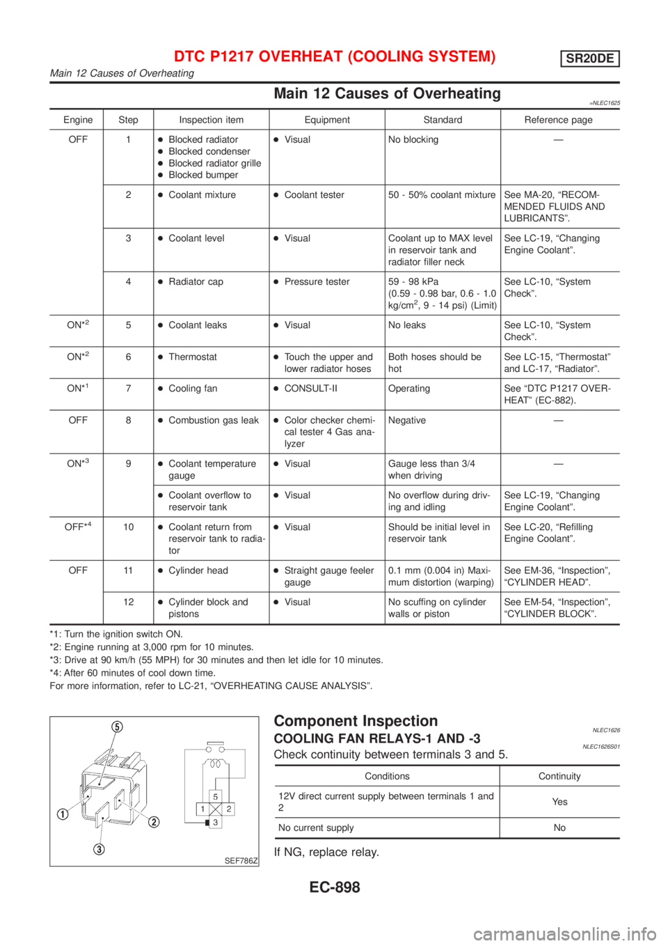
Main 12 Causes of Overheating=NLEC1625
Engine Step Inspection item Equipment Standard Reference page
OFF 1+Blocked radiator
+Blocked condenser
+Blocked radiator grille
+Blocked bumper+Visual No blocking Ð
2+Coolant mixture+Coolant tester 50 - 50% coolant mixture See MA-20, ªRECOM-
MENDED FLUIDS AND
LUBRICANTSº.
3+Coolant level+Visual Coolant up to MAX level
in reservoir tank and
radiator filler neckSee LC-19, ªChanging
Engine Coolantº.
4+Radiator cap+Pressure tester 59 - 98 kPa
(0.59 - 0.98 bar, 0.6 - 1.0
kg/cm
2,9-14psi) (Limit)See LC-10, ªSystem
Checkº.
ON*
25+Coolant leaks+Visual No leaks See LC-10, ªSystem
Checkº.
ON*
26+Thermostat+Touch the upper and
lower radiator hosesBoth hoses should be
hotSee LC-15, ªThermostatº
and LC-17, ªRadiatorº.
ON*
17+Cooling fan+CONSULT-II Operating See ªDTC P1217 OVER-
HEATº (EC-882).
OFF 8+Combustion gas leak+Color checker chemi-
cal tester 4 Gas ana-
lyzerNegative Ð
ON*
39+Coolant temperature
gauge+Visual Gauge less than 3/4
when drivingÐ
+Coolant overflow to
reservoir tank+Visual No overflow during driv-
ing and idlingSee LC-19, ªChanging
Engine Coolantº.
OFF*
410+Coolant return from
reservoir tank to radia-
tor+Visual Should be initial level in
reservoir tankSee LC-20, ªRefilling
Engine Coolantº.
OFF 11+Cylinder head+Straight gauge feeler
gauge0.1 mm (0.004 in) Maxi-
mum distortion (warping)See EM-36, ªInspectionº,
ªCYLINDER HEADº.
12+Cylinder block and
pistons+Visual No scuffing on cylinder
walls or pistonSee EM-54, ªInspectionº,
ªCYLINDER BLOCKº.
*1: Turn the ignition switch ON.
*2: Engine running at 3,000 rpm for 10 minutes.
*3: Drive at 90 km/h (55 MPH) for 30 minutes and then let idle for 10 minutes.
*4: After 60 minutes of cool down time.
For more information, refer to LC-21, ªOVERHEATING CAUSE ANALYSISº.
SEF786Z
Component InspectionNLEC1626COOLING FAN RELAYS-1 AND -3NLEC1626S01Check continuity between terminals 3 and 5.
Conditions Continuity
12V direct current supply between terminals 1 and
2Ye s
No current supply No
If NG, replace relay.
DTC P1217 OVERHEAT (COOLING SYSTEM)SR20DE
Main 12 Causes of Overheating
EC-898
Page 1627 of 3051
![NISSAN ALMERA TINO 2001 Service Repair Manual TERMI-
NAL
NO.WIRE
COLORITEM CONDITION DATA(DC Voltage)
221 LG/B Cooling fan relay (High)[Engine is running]
+Cooling fans are not operating
+Cooling fans are operating at low speedBATTERY VOLTAGE
(11 NISSAN ALMERA TINO 2001 Service Repair Manual TERMI-
NAL
NO.WIRE
COLORITEM CONDITION DATA(DC Voltage)
221 LG/B Cooling fan relay (High)[Engine is running]
+Cooling fans are not operating
+Cooling fans are operating at low speedBATTERY VOLTAGE
(11](/manual-img/5/57352/w960_57352-1626.png)
TERMI-
NAL
NO.WIRE
COLORITEM CONDITION DATA(DC Voltage)
221 LG/B Cooling fan relay (High)[Engine is running]
+Cooling fans are not operating
+Cooling fans are operating at low speedBATTERY VOLTAGE
(11 - 14V)
[Engine is running]
+Cooling fans are operating at high speedApproximately 0.1V
On Board Diagnosis LogicNLEC0663This diagnosis continuously monitors the engine coolant temperature.
If the cooling fan or another component in the cooling system malfunctions, engine coolant temperature will
rise.
When the engine coolant temperature reaches an abnormally high temperature condition, a malfunction is
indicated.
DTC Malfunction is detected when ... Check Items (Possible Cause)
P1217
0208+Cooling fan does not operate properly (Overheat).
+Cooling fan system does not operate properly
(Overheat).
+Engine coolant was not added to the system using
the proper filling method.+Harness or connectors
(The cooling fan circuit is open or shorted.)
+Cooling fan
+Radiator hose
+Radiator
+Radiator cap
+Water pump
+Thermostat
+Engine coolant temperature sensor
For more information, refer to ªMAIN 12 CAUSES OF
OVERHEATINGº, EC-1217.
CAUTION:
When a malfunction is indicated, be sure to replace the coolant following the procedure in the LC-59,
ªChanging Engine Coolantº. Also, replace the engine oil.
1) Fill radiator with coolant up to specified level with a filling speed of 2 liters per minute. Be sure
to use coolant with the proper mixture ratio. Refer to MA-22, ªEngine Coolant Mixture Ratioº.
2) After refilling coolant, run engine to ensure that no water-flow noise is emitted.
DTC P1217 OVER HEATYD22DDTI
ECM Terminals and Reference Value (Cont'd)
EC-1202
Page 1636 of 3051
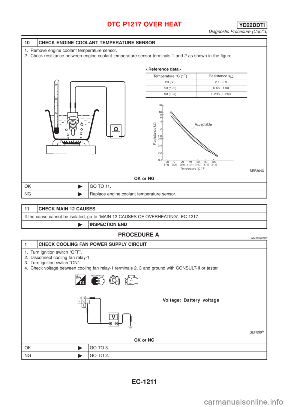
10 CHECK ENGINE COOLANT TEMPERATURE SENSOR
1. Remove engine coolant temperature sensor.
2. Check resistance between engine coolant temperature sensor terminals 1 and 2 as shown in the figure.
SEF304X
OK or NG
OK©GO TO 11.
NG©Replace engine coolant temperature sensor.
11 CHECK MAIN 12 CAUSES
If the cause cannot be isolated, go to ªMAIN 12 CAUSES OF OVERHEATINGº, EC-1217.
©INSPECTION END
PROCEDURE ANLEC0666S05
1 CHECK COOLING FAN POWER SUPPLY CIRCUIT
1. Turn ignition switch ªOFFº.
2. Disconnect cooling fan relay-1.
3. Turn ignition switch ªONº.
4. Check voltage between cooling fan relay-1 terminals 2, 3 and ground with CONSULT-II or tester.
SEF899Y
OK or NG
OK©GO TO 3.
NG©GO TO 2.
DTC P1217 OVER HEATYD22DDTI
Diagnostic Procedure (Cont'd)
EC-1211
Page 1642 of 3051
9 CHECK INTERMITTENT INCIDENT
1. Perform ªTROUBLE DIAGNOSIS FOR INTERMITTENT INCIDENTº, EC-1135.
©INSPECTION END
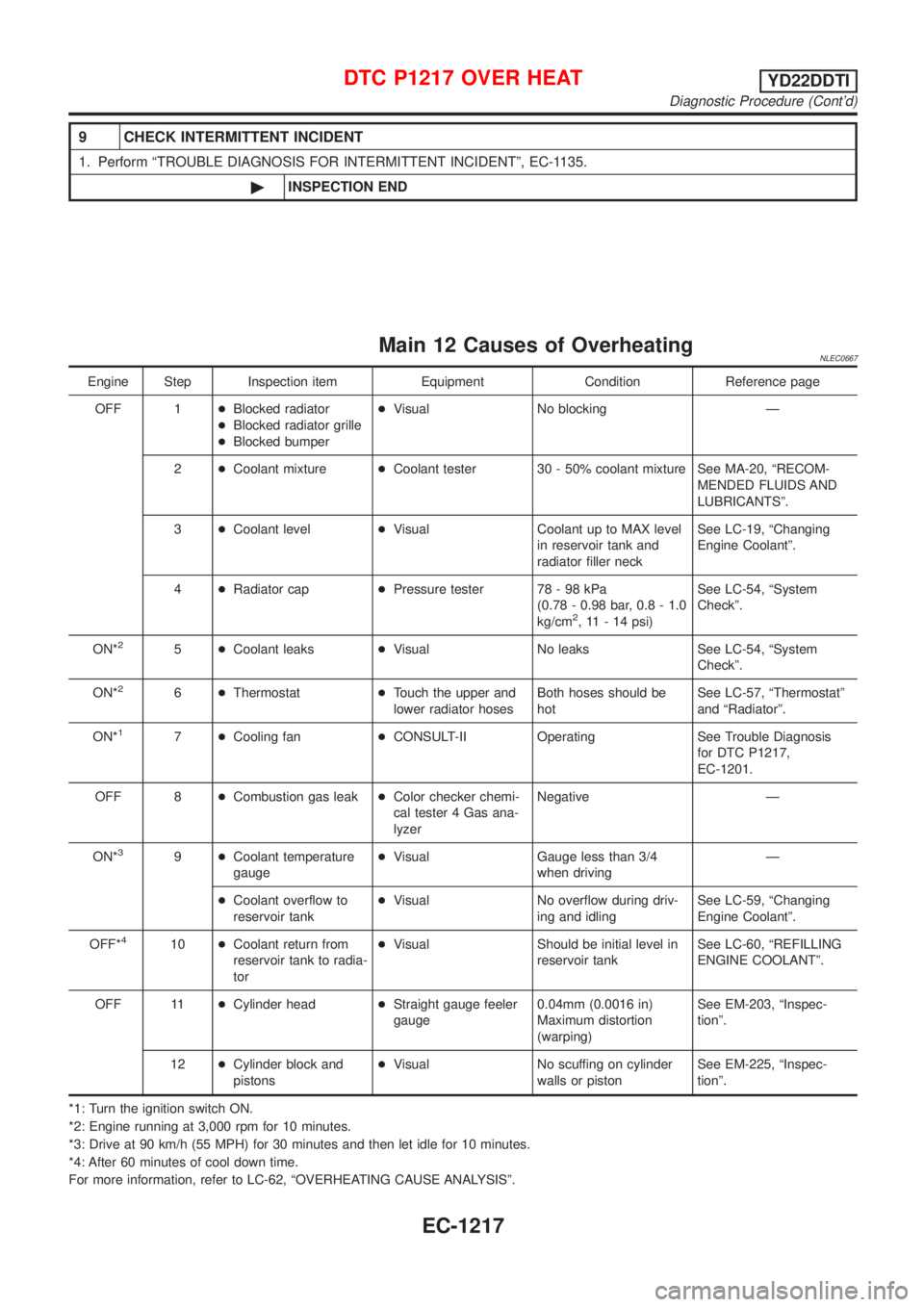
Main 12 Causes of OverheatingNLEC0667
Engine Step Inspection item Equipment Condition Reference page
OFF 1+Blocked radiator
+Blocked radiator grille
+Blocked bumper+Visual No blocking Ð
2+Coolant mixture+Coolant tester 30 - 50% coolant mixture See MA-20, ªRECOM-
MENDED FLUIDS AND
LUBRICANTSº.
3+Coolant level+Visual Coolant up to MAX level
in reservoir tank and
radiator filler neckSee LC-19, ªChanging
Engine Coolantº.
4+Radiator cap+Pressure tester 78 - 98 kPa
(0.78 - 0.98 bar, 0.8 - 1.0
kg/cm
2, 11 - 14 psi)See LC-54, ªSystem
Checkº.
ON*
25+Coolant leaks+Visual No leaks See LC-54, ªSystem
Checkº.
ON*
26+Thermostat+Touch the upper and
lower radiator hosesBoth hoses should be
hotSee LC-57, ªThermostatº
and ªRadiatorº.
ON*
17+Cooling fan+CONSULT-II Operating See Trouble Diagnosis
for DTC P1217,
EC-1201.
OFF 8+Combustion gas leak+Color checker chemi-
cal tester 4 Gas ana-
lyzerNegative Ð
ON*
39+Coolant temperature
gauge+Visual Gauge less than 3/4
when drivingÐ
+Coolant overflow to
reservoir tank+Visual No overflow during driv-
ing and idlingSee LC-59, ªChanging
Engine Coolantº.
OFF*
410+Coolant return from
reservoir tank to radia-
tor+Visual Should be initial level in
reservoir tankSee LC-60, ªREFILLING
ENGINE COOLANTº.
OFF 11+Cylinder head+Straight gauge feeler
gauge0.04mm (0.0016 in)
Maximum distortion
(warping)See EM-203, ªInspec-
tionº.
12+Cylinder block and
pistons+Visual No scuffing on cylinder
walls or pistonSee EM-225, ªInspec-
tionº.
*1: Turn the ignition switch ON.
*2: Engine running at 3,000 rpm for 10 minutes.
*3: Drive at 90 km/h (55 MPH) for 30 minutes and then let idle for 10 minutes.
*4: After 60 minutes of cool down time.
For more information, refer to LC-62, ªOVERHEATING CAUSE ANALYSISº.
DTC P1217 OVER HEATYD22DDTI
Diagnostic Procedure (Cont'd)
EC-1217
Page 2704 of 3051
ENGINE LUBRICATION &
COOLING SYSTEMS
SECTION
LC
CONTENTS
QG
ENGINE LUBRICATION SYSTEM..................................3
Precautions ..................................................................3
LIQUID GASKET APPLICATION PROCEDURE............3
Preparation ..................................................................3
SPECIAL SERVICE TOOLS........................................3
Lubrication Circuit ........................................................4
Oil Pressure Check......................................................5
Oil Pump ......................................................................5
REMOVAL AND INSTALLATION.................................5
DISASSEMBLY AND ASSEMBLY................................6
INSPECTION.............................................................7
REGULATOR VALVE INSPECTION............................7
Changing Engine Oil....................................................8
Changing Oil Filter .......................................................9
Service Data and Specifications (SDS).....................10
OIL PRESSURE CHECK..........................................10
OIL PUMP INSPECTION..........................................10
REGULATOR VALVE INSPECTION..........................10
OIL CAPACITY........................................................10
ENGINE COOLING SYSTEM........................................ 11
Precautions ................................................................ 11
LIQUID GASKET APPLICATION PROCEDURE.......... 11
Preparation ................................................................ 11
SPECIAL SERVICE TOOLS...................................... 11
Cooling Circuit ...........................................................12
System Check............................................................12
CHECKING COOLING SYSTEM HOSES...................12
CHECKING RADIATOR............................................13
CHECKING RADIATOR CAP....................................13
CHECKING COOLING SYSTEM FOR LEAKS............13
Water Pump ...............................................................14
REMOVAL AND INSTALLATION...............................14
INSPECTION...........................................................14
Thermostat .................................................................15
REMOVAL AND INSTALLATION...............................15
INSPECTION...........................................................16
Radiator .....................................................................17
COMPONENTS.......................................................17
Cooling Fan ...............................................................18
COMPONENTS.......................................................18
CONTROL SYSTEM................................................19
Changing Engine Coolant..........................................19
- DRAINING ENGINE COOLANT -............................19
- REFILLING ENGINE COOLANT -...........................20
- FLUSHING COOLING SYSTEM -............................20
Overheating Cause Analysis .....................................21
Service Data and Specifications (SDS).....................22
THERMOSTAT........................................................22
RADIATOR..............................................................22
COOLANT CAPACITY..............................................22
SR
ENGINE LUBRICATION SYSTEM................................23
Precautions ................................................................23
LIQUID GASKET APPLICATION PROCEDURE..........23
Preparation ................................................................23
SPECIAL SERVICE TOOLS......................................23
Lubrication Circuit ......................................................24
Oil Pressure Check....................................................25
Oil Pump ....................................................................25
REMOVAL AND INSTALLATION...............................25
DISASSEMBLY AND ASSEMBLY..............................26
INSPECTION...........................................................26
REGULATOR VALVE INSPECTION..........................27
Changing Engine Oil..................................................28
Changing Engine Oil Filter ........................................28
Oil Filter .....................................................................29
Oil Cooler ...................................................................29
REMOVAL AND INSTALLATION...............................29
INSPECTION...........................................................30
Service Data and Specifications (SDS).....................30
OIL PRESSURE CHECK..........................................30
REGULATOR VALVE INSPECTION..........................30
OIL PUMP INSPECTION..........................................30
OIL CAPACITY........................................................30
ENGINE COOLING SYSTEM........................................31
Precautions ................................................................31
LIQUID GASKET APPLICATION PROCEDURE..........31
Preparation ................................................................31