2001 NISSAN ALMERA TINO air condition
[x] Cancel search: air conditionPage 609 of 3051
SEF463R
SEF288D
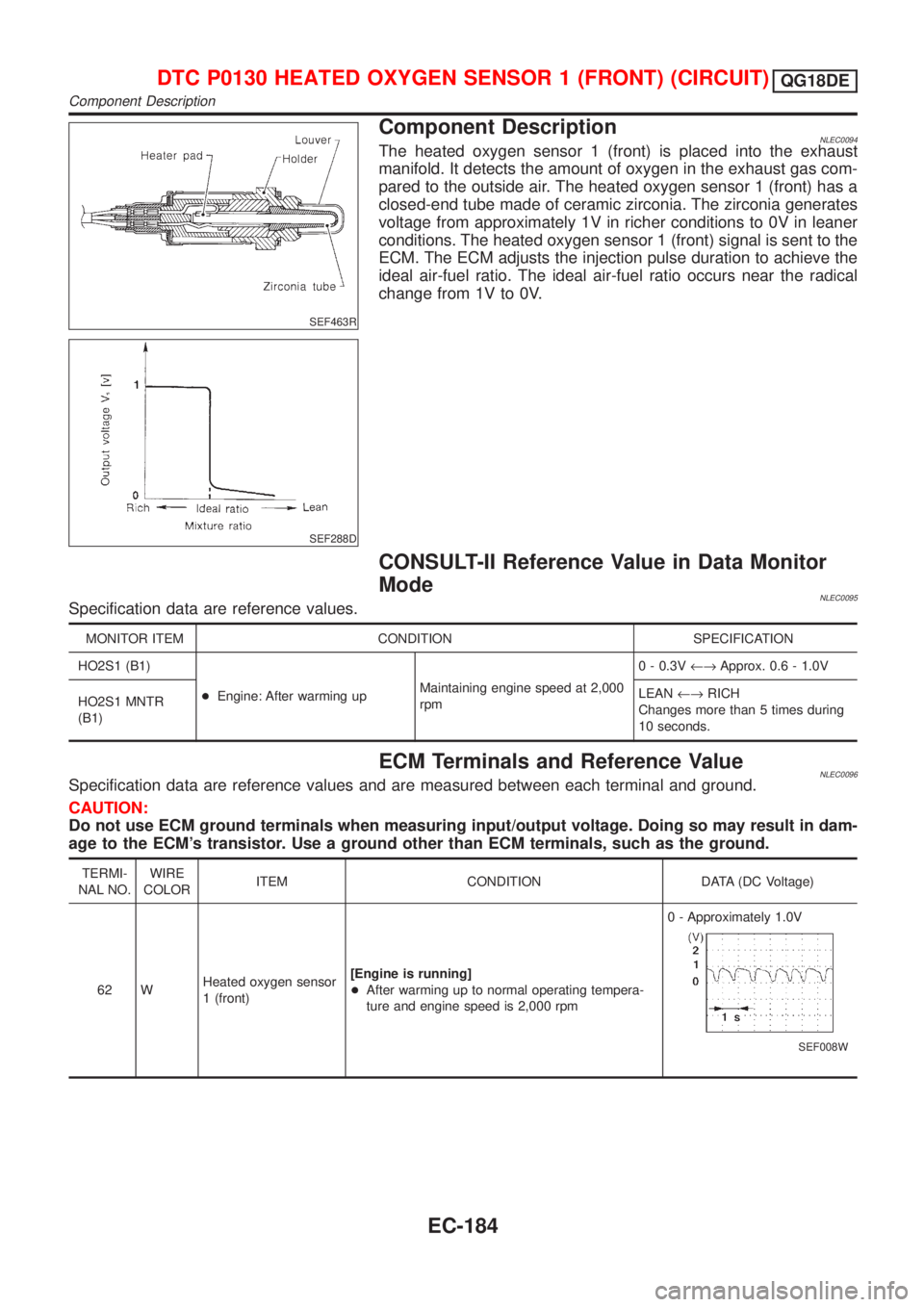
Component DescriptionNLEC0094The heated oxygen sensor 1 (front) is placed into the exhaust
manifold. It detects the amount of oxygen in the exhaust gas com-
pared to the outside air. The heated oxygen sensor 1 (front) has a
closed-end tube made of ceramic zirconia. The zirconia generates
voltage from approximately 1V in richer conditions to 0V in leaner
conditions. The heated oxygen sensor 1 (front) signal is sent to the
ECM. The ECM adjusts the injection pulse duration to achieve the
ideal air-fuel ratio. The ideal air-fuel ratio occurs near the radical
change from 1V to 0V.
CONSULT-II Reference Value in Data Monitor
Mode
NLEC0095Specification data are reference values.
MONITOR ITEM CONDITION SPECIFICATION
HO2S1 (B1)
+Engine: After warming upMaintaining engine speed at 2,000
rpm0 - 0.3V¨Approx. 0.6 - 1.0V
HO2S1 MNTR
(B1)LEAN¨RICH
Changes more than 5 times during
10 seconds.
ECM Terminals and Reference ValueNLEC0096Specification data are reference values and are measured between each terminal and ground.
CAUTION:
Do not use ECM ground terminals when measuring input/output voltage. Doing so may result in dam-
age to the ECM's transistor. Use a ground other than ECM terminals, such as the ground.
TERMI-
NAL NO.WIRE
COLORITEM CONDITION DATA (DC Voltage)
62 WHeated oxygen sensor
1 (front)[Engine is running]
+After warming up to normal operating tempera-
ture and engine speed is 2,000 rpm0 - Approximately 1.0V
SEF008W
DTC P0130 HEATED OXYGEN SENSOR 1 (FRONT) (CIRCUIT)QG18DE
Component Description
EC-184
Page 617 of 3051
SEF463R
SEF288D
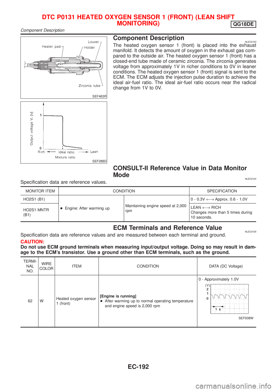
Component DescriptionNLEC0103The heated oxygen sensor 1 (front) is placed into the exhaust
manifold. It detects the amount of oxygen in the exhaust gas com-
pared to the outside air. The heated oxygen sensor 1 (front) has a
closed-end tube made of ceramic zirconia. The zirconia generates
voltage from approximately 1V in richer conditions to 0V in leaner
conditions. The heated oxygen sensor 1 (front) signal is sent to the
ECM. The ECM adjusts the injection pulse duration to achieve the
ideal air-fuel ratio. The ideal air-fuel ratio occurs near the radical
change from 1V to 0V.
CONSULT-II Reference Value in Data Monitor
Mode
NLEC0104Specification data are reference values.
MONITOR ITEM CONDITION SPECIFICATION
HO2S1 (B1)
+Engine: After warming upMaintaining engine speed at 2,000
rpm0 - 0.3V¨Approx. 0.6 - 1.0V
HO2S1 MNTR
(B1)LEAN¨RICH
Changes more than 5 times during
10 seconds.
ECM Terminals and Reference ValueNLEC0105Specification data are reference values and are measured between each terminal and ground.
CAUTION:
Do not use ECM ground terminals when measuring input/output voltage. Doing so may result in dam-
age to the ECM's transistor. Use a ground other than ECM terminals, such as the ground.
TERMI-
NAL
NO.WIRE
COLORITEM CONDITION DATA (DC Voltage)
62 WHeated oxygen sensor
1 (front)[Engine is running]
+After warming up to normal operating temperature
and engine speed is 2,000 rpm0 - Approximately 1.0V
SEF008W
DTC P0131 HEATED OXYGEN SENSOR 1 (FRONT) (LEAN SHIFT
MONITORING)
QG18DE
Component Description
EC-192
Page 618 of 3051
SEF300U
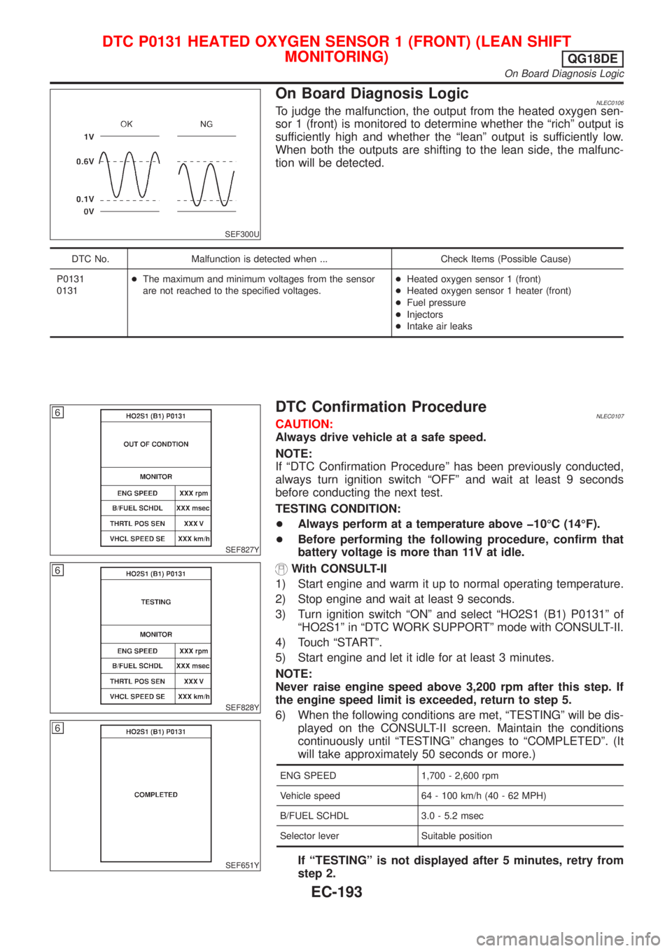
On Board Diagnosis LogicNLEC0106To judge the malfunction, the output from the heated oxygen sen-
sor 1 (front) is monitored to determine whether the ªrichº output is
sufficiently high and whether the ªleanº output is sufficiently low.
When both the outputs are shifting to the lean side, the malfunc-
tion will be detected.
DTC No. Malfunction is detected when ... Check Items (Possible Cause)
P0131
0131+The maximum and minimum voltages from the sensor
are not reached to the specified voltages.+Heated oxygen sensor 1 (front)
+Heated oxygen sensor 1 heater (front)
+Fuel pressure
+Injectors
+Intake air leaks
SEF827Y
SEF828Y
SEF651Y
DTC Confirmation ProcedureNLEC0107CAUTION:
Always drive vehicle at a safe speed.
NOTE:
If ªDTC Confirmation Procedureº has been previously conducted,
always turn ignition switch ªOFFº and wait at least 9 seconds
before conducting the next test.
TESTING CONDITION:
+Always perform at a temperature above þ10ÉC (14ÉF).
+Before performing the following procedure, confirm that
battery voltage is more than 11V at idle.
With CONSULT-II
1) Start engine and warm it up to normal operating temperature.
2) Stop engine and wait at least 9 seconds.
3) Turn ignition switch ªONº and select ªHO2S1 (B1) P0131º of
ªHO2S1º in ªDTC WORK SUPPORTº mode with CONSULT-II.
4) Touch ªSTARTº.
5) Start engine and let it idle for at least 3 minutes.
NOTE:
Never raise engine speed above 3,200 rpm after this step. If
the engine speed limit is exceeded, return to step 5.
6) When the following conditions are met, ªTESTINGº will be dis-
played on the CONSULT-II screen. Maintain the conditions
continuously until ªTESTINGº changes to ªCOMPLETEDº. (It
will take approximately 50 seconds or more.)
ENG SPEED 1,700 - 2,600 rpm
Vehicle speed 64 - 100 km/h (40 - 62 MPH)
B/FUEL SCHDL 3.0 - 5.2 msec
Selector lever Suitable position
If ªTESTINGº is not displayed after 5 minutes, retry from
step 2.
DTC P0131 HEATED OXYGEN SENSOR 1 (FRONT) (LEAN SHIFT
MONITORING)
QG18DE
On Board Diagnosis Logic
EC-193
Page 623 of 3051
SEF463R
SEF288D
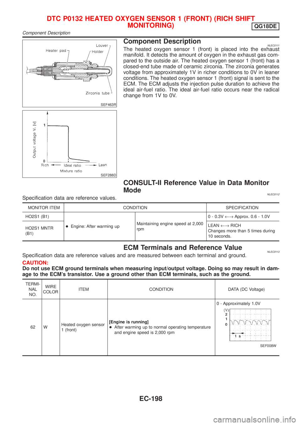
Component DescriptionNLEC0111The heated oxygen sensor 1 (front) is placed into the exhaust
manifold. It detects the amount of oxygen in the exhaust gas com-
pared to the outside air. The heated oxygen sensor 1 (front) has a
closed-end tube made of ceramic zirconia. The zirconia generates
voltage from approximately 1V in richer conditions to 0V in leaner
conditions. The heated oxygen sensor 1 (front) signal is sent to the
ECM. The ECM adjusts the injection pulse duration to achieve the
ideal air-fuel ratio. The ideal air-fuel ratio occurs near the radical
change from 1V to 0V.
CONSULT-II Reference Value in Data Monitor
Mode
NLEC0112Specification data are reference values.
MONITOR ITEM CONDITION SPECIFICATION
HO2S1 (B1)
+Engine: After warming upMaintaining engine speed at 2,000
rpm0 - 0.3V¨Approx. 0.6 - 1.0V
HO2S1 MNTR
(B1)LEAN¨RICH
Changes more than 5 times during
10 seconds.
ECM Terminals and Reference ValueNLEC0113Specification data are reference values and are measured between each terminal and ground.
CAUTION:
Do not use ECM ground terminals when measuring input/output voltage. Doing so may result in dam-
age to the ECM's transistor. Use a ground other than ECM terminals, such as the ground.
TERMI-
NAL
NO.WIRE
COLORITEM CONDITION DATA (DC Voltage)
62 WHeated oxygen sensor
1 (front)[Engine is running]
+After warming up to normal operating temperature
and engine speed is 2,000 rpm0 - Approximately 1.0V
SEF008W
DTC P0132 HEATED OXYGEN SENSOR 1 (FRONT) (RICH SHIFT
MONITORING)
QG18DE
Component Description
EC-198
Page 629 of 3051
SEF463R
SEF288D
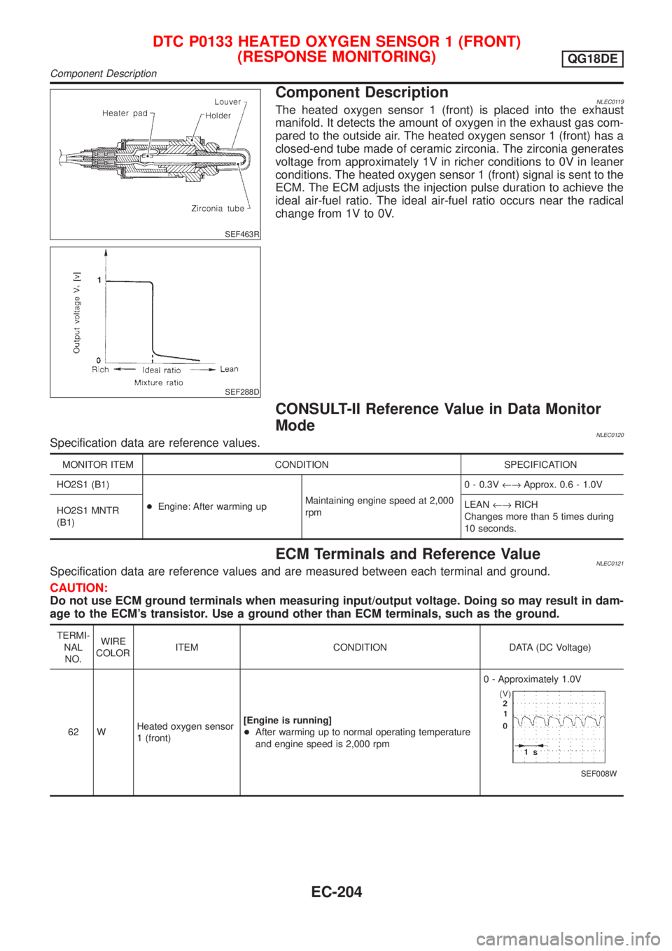
Component DescriptionNLEC0119The heated oxygen sensor 1 (front) is placed into the exhaust
manifold. It detects the amount of oxygen in the exhaust gas com-
pared to the outside air. The heated oxygen sensor 1 (front) has a
closed-end tube made of ceramic zirconia. The zirconia generates
voltage from approximately 1V in richer conditions to 0V in leaner
conditions. The heated oxygen sensor 1 (front) signal is sent to the
ECM. The ECM adjusts the injection pulse duration to achieve the
ideal air-fuel ratio. The ideal air-fuel ratio occurs near the radical
change from 1V to 0V.
CONSULT-II Reference Value in Data Monitor
Mode
NLEC0120Specification data are reference values.
MONITOR ITEM CONDITION SPECIFICATION
HO2S1 (B1)
+Engine: After warming upMaintaining engine speed at 2,000
rpm0 - 0.3V¨Approx. 0.6 - 1.0V
HO2S1 MNTR
(B1)LEAN¨RICH
Changes more than 5 times during
10 seconds.
ECM Terminals and Reference ValueNLEC0121Specification data are reference values and are measured between each terminal and ground.
CAUTION:
Do not use ECM ground terminals when measuring input/output voltage. Doing so may result in dam-
age to the ECM's transistor. Use a ground other than ECM terminals, such as the ground.
TERMI-
NAL
NO.WIRE
COLORITEM CONDITION DATA (DC Voltage)
62 WHeated oxygen sensor
1 (front)[Engine is running]
+After warming up to normal operating temperature
and engine speed is 2,000 rpm0 - Approximately 1.0V
SEF008W
DTC P0133 HEATED OXYGEN SENSOR 1 (FRONT)
(RESPONSE MONITORING)
QG18DE
Component Description
EC-204
Page 630 of 3051
SEF010V
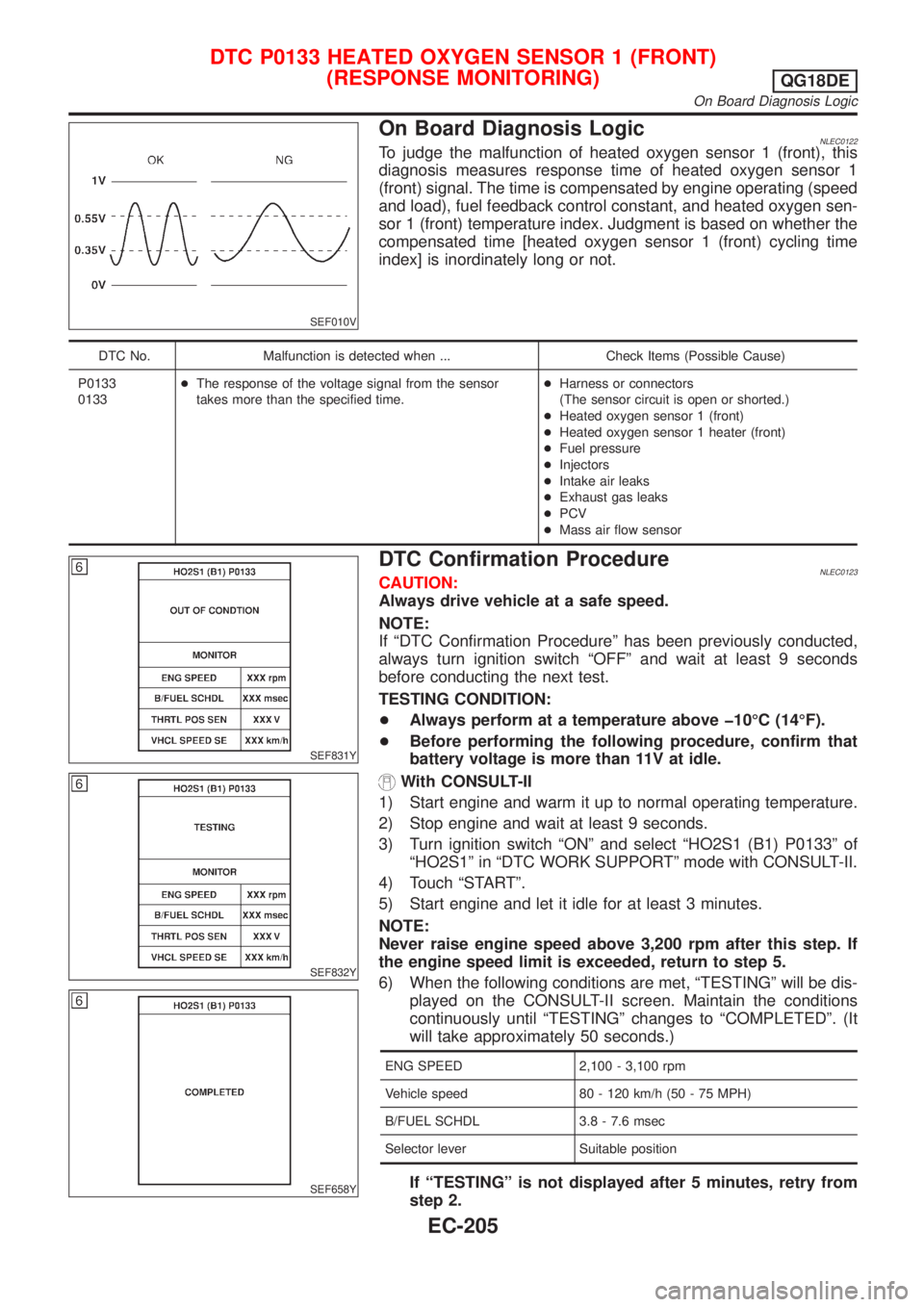
On Board Diagnosis LogicNLEC0122To judge the malfunction of heated oxygen sensor 1 (front), this
diagnosis measures response time of heated oxygen sensor 1
(front) signal. The time is compensated by engine operating (speed
and load), fuel feedback control constant, and heated oxygen sen-
sor 1 (front) temperature index. Judgment is based on whether the
compensated time [heated oxygen sensor 1 (front) cycling time
index] is inordinately long or not.
DTC No. Malfunction is detected when ... Check Items (Possible Cause)
P0133
0133+The response of the voltage signal from the sensor
takes more than the specified time.+Harness or connectors
(The sensor circuit is open or shorted.)
+Heated oxygen sensor 1 (front)
+Heated oxygen sensor 1 heater (front)
+Fuel pressure
+Injectors
+Intake air leaks
+Exhaust gas leaks
+PCV
+Mass air flow sensor
SEF831Y
SEF832Y
SEF658Y
DTC Confirmation ProcedureNLEC0123CAUTION:
Always drive vehicle at a safe speed.
NOTE:
If ªDTC Confirmation Procedureº has been previously conducted,
always turn ignition switch ªOFFº and wait at least 9 seconds
before conducting the next test.
TESTING CONDITION:
+Always perform at a temperature above þ10ÉC (14ÉF).
+Before performing the following procedure, confirm that
battery voltage is more than 11V at idle.
With CONSULT-II
1) Start engine and warm it up to normal operating temperature.
2) Stop engine and wait at least 9 seconds.
3) Turn ignition switch ªONº and select ªHO2S1 (B1) P0133º of
ªHO2S1º in ªDTC WORK SUPPORTº mode with CONSULT-II.
4) Touch ªSTARTº.
5) Start engine and let it idle for at least 3 minutes.
NOTE:
Never raise engine speed above 3,200 rpm after this step. If
the engine speed limit is exceeded, return to step 5.
6) When the following conditions are met, ªTESTINGº will be dis-
played on the CONSULT-II screen. Maintain the conditions
continuously until ªTESTINGº changes to ªCOMPLETEDº. (It
will take approximately 50 seconds.)
ENG SPEED 2,100 - 3,100 rpm
Vehicle speed 80 - 120 km/h (50 - 75 MPH)
B/FUEL SCHDL 3.8 - 7.6 msec
Selector lever Suitable position
If ªTESTINGº is not displayed after 5 minutes, retry from
step 2.
DTC P0133 HEATED OXYGEN SENSOR 1 (FRONT)
(RESPONSE MONITORING)
QG18DE
On Board Diagnosis Logic
EC-205
Page 639 of 3051
SEF463R
SEF288D
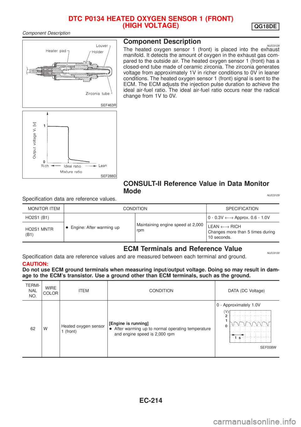
Component DescriptionNLEC0128The heated oxygen sensor 1 (front) is placed into the exhaust
manifold. It detects the amount of oxygen in the exhaust gas com-
pared to the outside air. The heated oxygen sensor 1 (front) has a
closed-end tube made of ceramic zirconia. The zirconia generates
voltage from approximately 1V in richer conditions to 0V in leaner
conditions. The heated oxygen sensor 1 (front) signal is sent to the
ECM. The ECM adjusts the injection pulse duration to achieve the
ideal air-fuel ratio. The ideal air-fuel ratio occurs near the radical
change from 1V to 0V.
CONSULT-II Reference Value in Data Monitor
Mode
NLEC0129Specification data are reference values.
MONITOR ITEM CONDITION SPECIFICATION
HO2S1 (B1)
+Engine: After warming upMaintaining engine speed at 2,000
rpm0 - 0.3V¨Approx. 0.6 - 1.0V
HO2S1 MNTR
(B1)LEAN¨RICH
Changes more than 5 times during
10 seconds.
ECM Terminals and Reference ValueNLEC0130Specification data are reference values and are measured between each terminal and ground.
CAUTION:
Do not use ECM ground terminals when measuring input/output voltage. Doing so may result in dam-
age to the ECM's transistor. Use a ground other than ECM terminals, such as the ground.
TERMI-
NAL
NO.WIRE
COLORITEM CONDITION DATA (DC Voltage)
62 WHeated oxygen sensor
1 (front)[Engine is running]
+After warming up to normal operating temperature
and engine speed is 2,000 rpm0 - Approximately 1.0V
SEF008W
DTC P0134 HEATED OXYGEN SENSOR 1 (FRONT)
(HIGH VOLTAGE)
QG18DE
Component Description
EC-214
Page 652 of 3051
SEF327R
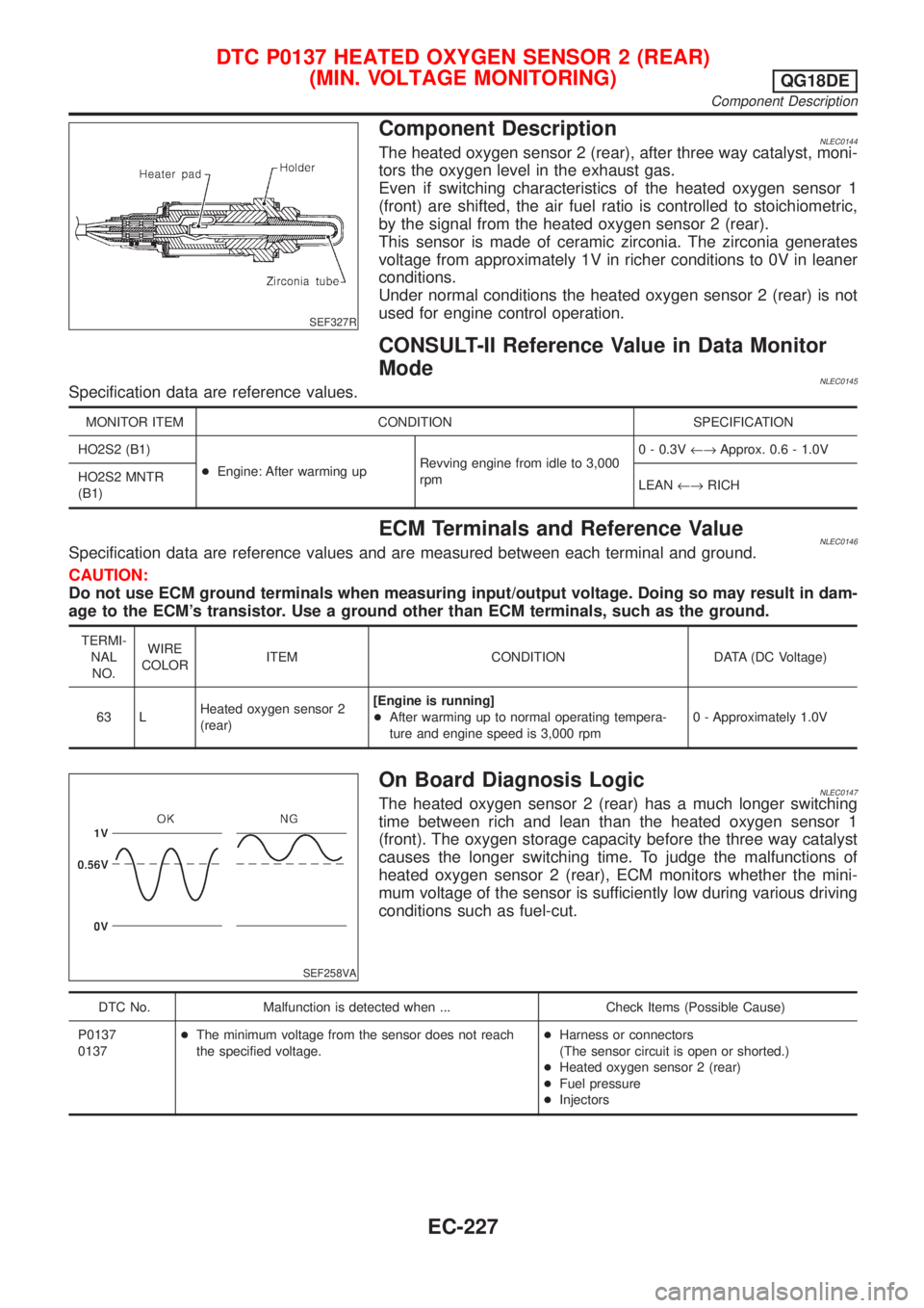
Component DescriptionNLEC0144The heated oxygen sensor 2 (rear), after three way catalyst, moni-
tors the oxygen level in the exhaust gas.
Even if switching characteristics of the heated oxygen sensor 1
(front) are shifted, the air fuel ratio is controlled to stoichiometric,
by the signal from the heated oxygen sensor 2 (rear).
This sensor is made of ceramic zirconia. The zirconia generates
voltage from approximately 1V in richer conditions to 0V in leaner
conditions.
Under normal conditions the heated oxygen sensor 2 (rear) is not
used for engine control operation.
CONSULT-II Reference Value in Data Monitor
Mode
NLEC0145Specification data are reference values.
MONITOR ITEM CONDITION SPECIFICATION
HO2S2 (B1)
+Engine: After warming upRevving engine from idle to 3,000
rpm0 - 0.3V¨Approx. 0.6 - 1.0V
HO2S2 MNTR
(B1)LEAN¨RICH
ECM Terminals and Reference ValueNLEC0146Specification data are reference values and are measured between each terminal and ground.
CAUTION:
Do not use ECM ground terminals when measuring input/output voltage. Doing so may result in dam-
age to the ECM's transistor. Use a ground other than ECM terminals, such as the ground.
TERMI-
NAL
NO.WIRE
COLORITEM CONDITION DATA (DC Voltage)
63 LHeated oxygen sensor 2
(rear)[Engine is running]
+After warming up to normal operating tempera-
ture and engine speed is 3,000 rpm0 - Approximately 1.0V
SEF258VA
On Board Diagnosis LogicNLEC0147The heated oxygen sensor 2 (rear) has a much longer switching
time between rich and lean than the heated oxygen sensor 1
(front). The oxygen storage capacity before the three way catalyst
causes the longer switching time. To judge the malfunctions of
heated oxygen sensor 2 (rear), ECM monitors whether the mini-
mum voltage of the sensor is sufficiently low during various driving
conditions such as fuel-cut.
DTC No. Malfunction is detected when ... Check Items (Possible Cause)
P0137
0137+The minimum voltage from the sensor does not reach
the specified voltage.+Harness or connectors
(The sensor circuit is open or shorted.)
+Heated oxygen sensor 2 (rear)
+Fuel pressure
+Injectors
DTC P0137 HEATED OXYGEN SENSOR 2 (REAR)
(MIN. VOLTAGE MONITORING)
QG18DE
Component Description
EC-227