Page 1539 of 2898

DescriptionNJEC0764SYSTEM DESCRIPTIONNJEC0764S01
Sensor Input Signal to ECM ECM Function Actuator
Electronic controlled fuel injection pump Fuel injection signal
EGR volume con-
trolEGR volume control
valve Crankshaft position sensor (TDC) Engine speed
Vehicle speed sensor Vehicle speed
Engine coolant temperature sensor Engine coolant temperature
Ignition switch Start signal
Accelerator position sensor Accelerator position
Mass air flow sensor Amount of intake air
Air conditioner switch Air conditioner operation
Electrical load Electrical load signal
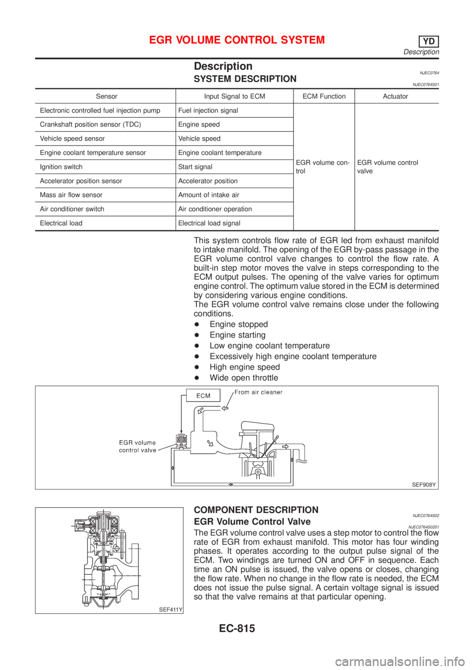
This system controls flow rate of EGR led from exhaust manifold
to intake manifold. The opening of the EGR by-pass passage in the
EGR volume control valve changes to control the flow rate. A
built-in step motor moves the valve in steps corresponding to the
ECM output pulses. The opening of the valve varies for optimum
engine control. The optimum value stored in the ECM is determined
by considering various engine conditions.
The EGR volume control valve remains close under the following
conditions.
+Engine stopped
+Engine starting
+Low engine coolant temperature
+Excessively high engine coolant temperature
+High engine speed
+Wide open throttle
SEF908Y
SEF411Y
COMPONENT DESCRIPTIONNJEC0764S02EGR Volume Control ValveNJEC0764S0201The EGR volume control valve uses a step motor to control the flow
rate of EGR from exhaust manifold. This motor has four winding
phases. It operates according to the output pulse signal of the
ECM. Two windings are turned ON and OFF in sequence. Each
time an ON pulse is issued, the valve opens or closes, changing
the flow rate. When no change in the flow rate is needed, the ECM
does not issue the pulse signal. A certain voltage signal is issued
so that the valve remains at that particular opening.
EGR VOLUME CONTROL SYSTEMYD
Description
EC-815
Page 1558 of 2898
General SpecificationsNJEC0788Unit: rpm
Engine YD22DDT
Idle speed 725±25
Maximum engine speed 4,900
Injection NozzleNJEC0790Unit: kPa (bar, kg/cm2, psi)
Initial injection pressureNew 21,476 - 22,457 (214.7 - 224.5, 219 - 229, 3,114 - 3,256)
Limit 18,275 (182.7, 186, 2,650)
Engine Coolant Temperature SensorNJEC0791
Temperature ÉC (ÉF) Resistance kW
20 (68) 2.1 - 2.9
50 (122) 0.68 - 1.00
90 (194) 0.236 - 0.260
Crankshaft Position Sensor (TDC)NJEC0792
Resistance [at 20ÉC (68ÉF)]W495 - 605
Glow PlugNJEC0793
Resistance [at 25ÉC (77ÉF)]W0.8
Accelerator Position SensorNJEC0794
Throttle valve conditions Resistance between terminals 2 and 4 kW[at 25ÉC (77ÉF)]
Completely closed0.9 - 1.3
Partially open0.9 - 2.1
Completely open1.7 - 2.1
EGR Volume Control ValveNJEC0795
Resistance [at 25ÉC (77ÉF)]W13-17
SERVICE DATA AND SPECIFICATIONS (SDS)YD
General Specifications
EC-834
Page 1563 of 2898

Supplemental Restraint System (SRS) ªAIR
BAGº and ªSEAT BELT PRE-TENSIONERº
NJEL0001The Supplemental Restraint System such as ªAIR BAGº and ªSEAT BELT PRE-TENSIONERº used along with
a seat belt, helps to reduce the risk or severity of injury to the driver and front passenger for certain types of
collision. The SRS system composition which is available to NISSAN MODEL N16 is as follows (The compo-
sition varies according to the destination and optional equipment.):
+For a frontal collision
The Supplemental Restraint System consists of driver air bag module (located in the center of the steer-
ing wheel), front passenger air bag module (located on the instrument panel on passenger side), front seat
belt pre-tensioners, a diagnosis sensor unit, warning lamp, wiring harness and spiral cable.
+For a side collision
The Supplemental Restraint System consists of front side air bag module (located in the outer side of front
seat), side air bag (satellite) sensor, diagnosis sensor unit (one of components of air bags for a frontal
collision), wiring harness, warning lamp (one of components of air bags for a frontal collision).
Information necessary to service the system safely is included in theRS sectionof this Service Manual.
WARNING:
+To avoid rendering the SRS inoperative, which could increase the risk of personal injury or death
in the event of a collision which would result in air bag inflation, all maintenance should be per-
formed by an authorized NISSAN dealer.
+Improper maintenance, including incorrect removal and installation of the SRS, can lead to per-
sonal injury caused by unintentional activation of the system. For removal of Spiral Cable and Air
Bag Module, see the RS section.
+Do not use electrical test equipment on any circuit related to the SRS unless instructed to in this
Service Manual. SRS wiring harnesses can be identified by yellow harness connector.
Wiring Diagrams and Trouble DiagnosisNJEL0002When you read wiring diagrams, refer to the following:
+Refer to GI-11, ªHOW TO READ WIRING DIAGRAMSº
+Refer to EL-10, ªPOWER SUPPLY ROUTINGº for power distribution circuit
When you perform trouble diagnosis, refer to the following:
+Refer to GI-32, ªHOW TO FOLLOW TEST GROUPS IN TROUBLE DIAGNOSESº
+Refer to GI-21, ªHOW TO PERFORM EFFICIENT DIAGNOSIS FOR AN ELECTRICAL INCIDENTº
Check for any Service bulletins before servicing the vehicle.
PRECAUTIONS
Supplemental Restraint System (SRS) ªAIR BAGº and ªSEAT BELT PRE-TENSIONERº
EL-5
Page 1673 of 2898
![NISSAN ALMERA 2001 Service Manual System Description/Sedan With Interior Room
Lamp Timer
=NJEL0366POWER SUPPLY AND GROUNDNJEL0366S01Power is supplied at all times:
+through 10A fuse [No. 12, located in the fuse block (J/B)]
+to key sw NISSAN ALMERA 2001 Service Manual System Description/Sedan With Interior Room
Lamp Timer
=NJEL0366POWER SUPPLY AND GROUNDNJEL0366S01Power is supplied at all times:
+through 10A fuse [No. 12, located in the fuse block (J/B)]
+to key sw](/manual-img/5/57348/w960_57348-1672.png)
System Description/Sedan With Interior Room
Lamp Timer
=NJEL0366POWER SUPPLY AND GROUNDNJEL0366S01Power is supplied at all times:
+through 10A fuse [No. 12, located in the fuse block (J/B)]
+to key switch terminal 1 and
+to time control unit terminal 1
+through 10A fuse [No. 13, located in the fuse block (J/B)]
+to interior room lamp terminal 1.
When the key is removed from ignition key cylinder, power is interrupted:
+through key switch terminal 2
+to time control unit terminal 18.
With the ignition key switch in the ON or START position, power is supplied:
+through 10A fuse [No. 10, located in the fuse block (J/B)]
+to time control unit terminal 17.
Ground is supplied:
+through body grounds terminals M28 and M67
+to time control unit terminal 16
When the driver side door is opened, ground is supplied:
+through body grounds B9, B21 and B308
+to door switch driver side terminal 3
+from door switch driver side terminal 2
+to time control unit terminal 30.
When any door is opened, ground is supplied:
+through case ground of each door switch
+to each door switch terminal 1
+to time control unit terminal 31.
When the driver side door is unlocked, the time control unit receives a ground signal:
+through body grounds terminals M28 and M67
+to door unlock sensor terminal 2
+from door unlock sensor terminal 5
+to time control unit terminal 28.
When a signal, or combination of signals is received by the time control unit, ground is supplied:
+through time control unit terminal 26
+to interior room lamp terminal 2.
With power and ground supplied, the interior room lamp illuminates.
SWITCH OPERATIONNJEL0366S02When interior room lamp switch is ON, ground is supplied:
+through case grounds of interior room lamp
+to interior room lamp.
INTERIOR ROOM LAMP TIMER OPERATIONNJEL0366S03When interior room lamp switch is in the ªDOORº position, the time control unit keeps the interior room lamp
illuminated for about 30 seconds when:
+unlock signal is supplied from driver's door unlock sensor or multi-remote controller while all doors are
closed and key is out of ignition key cylinder
+key is removed from ignition key cylinder while all doors are closed
+driver's door is opened and then closed while key is out of the iginition key cylinder. (However, if the driv-
er's door is closed with the key inserted in the ignition key cylinder after the driver's door is opened with
the key removed, the timer is operated.)
The timer is canceled when:
+driver's door is locked,
INTERIOR ROOM LAMP
System Description/Sedan With Interior Room Lamp Timer
EL-115
Page 1678 of 2898
3 CHECK DRIVER SIDE DOOR SWITCH
Check continuity between door switch terminals 2 and 3.
SEL325WA
OK or NG
OK©Check the following.
+Driver side door switch ground circuit and condition
+Harness for open or short between time control unit and driver side door switch
NG©Replace driver side door switch.
4 CHECK FRONT DOOR UNLOCK SENSOR INPUT SIGNAL
Check voltage between time control unit harness connector terminal 28 and ground.
SEL987W
OK or NG
OK©GO TO 6.
NG©GO TO 5.
INTERIOR ROOM LAMP
Trouble Diagnoses/Sedan With Interior Room Lamp Timer (Cont'd)
EL-120
Page 1679 of 2898
5 CHECK FRONT DOOR UNLOCK SENSOR
1. Disconnect front door unlock sensor harness connector.
2. Check continuity between door unlock sensor terminals.
SEL908X
OK or NG
OK©Check the following.
+Door unlock sensor ground circuit
+Harness for open or short between time control unit and door unlock sensor
NG©Replace door unlock sensor.
6 CHECK DOOR SWITCHES INPUT SIGNAL
Check voltage between time control unit harness connector terminal 31 and ground.
SEL989W
OK or NG
OK©GO TO 8.
NG©GO TO 7.
INTERIOR ROOM LAMP
Trouble Diagnoses/Sedan With Interior Room Lamp Timer (Cont'd)
EL-121
Page 1683 of 2898
3 CHECK DRIVER SIDE DOOR SWITCH
Check continuity between terminals 2 and 3.
SEL325WA
OK or NG
OK©Check the following.
+Driver side door switch ground circuit and condition
+Harness for open or short between time control unit and driver side door switch
NG©Replace driver side door switch.
4 CHECK FRONT DOOR UNLOCK SENSOR INPUT SIGNAL
Check voltage between time control unit harness connector terminal 28 and ground.
SEL987W
OK or NG
OK©Replace time control unit.
NG©GO TO 5.
INTERIOR ROOM LAMP
Trouble Diagnoses/Sedan With Interior Room Lamp Timer (Cont'd)
EL-125
Page 1684 of 2898
5 CHECK FRONT DOOR UNLOCK SENSOR
1. Disconnect front door unlock sensor harness connector.
2. Check continuity between door unlock sensor terminals.
SEL908X
OK or NG
OK©Check the following.
+Door unlock sensor ground circuit
+Harness for open or short between time control unit and door unlock sensor
NG©Replace door unlock sensor.
INTERIOR ROOM LAMP
Trouble Diagnoses/Sedan With Interior Room Lamp Timer (Cont'd)
EL-126