Page 1741 of 2898
SEL498X
Electrical Components Inspection/Hatchback=NJEL0449FUEL LEVEL SENSOR UNIT CHECKNJEL0449S02+For removal, refer to FE-6, FE-23, ªFUEL SYSTEMº.
Check the resistance between terminals 4 and 1.
Ohmmeter
Float position mm (in)Resistance
valueW
(+) (þ)
41*1 Full 142.5 (5.61) Approx.4-6
*2 1/2 88.7 (3.492) 32 - 33
*3 Empty 11.1 (0.437) 80 - 83
*1 and *3: When float rod is in contact with stopper.
MEL424F
THERMAL TRANSMITTER CHECKNJEL0449S03Check the resistance between the terminals of thermal transmitter
and body ground.
Water temperature Resistance
65ÉC (149ÉF) Approx. 1,179 - 1,417W
91ÉC (196ÉF) Approx. 474 - 568W
CEL219AA
VEHICLE SPEED SENSOR SIGNAL CHECKNJEL0449S041. Remove vehicle speed sensor from transmission.
2. Turn vehicle speed sensor pinion quickly and measure voltage
across 1 and 2.
METERS AND GAUGES
Electrical Components Inspection/Hatchback
EL-183
Page 1752 of 2898

SEL977W
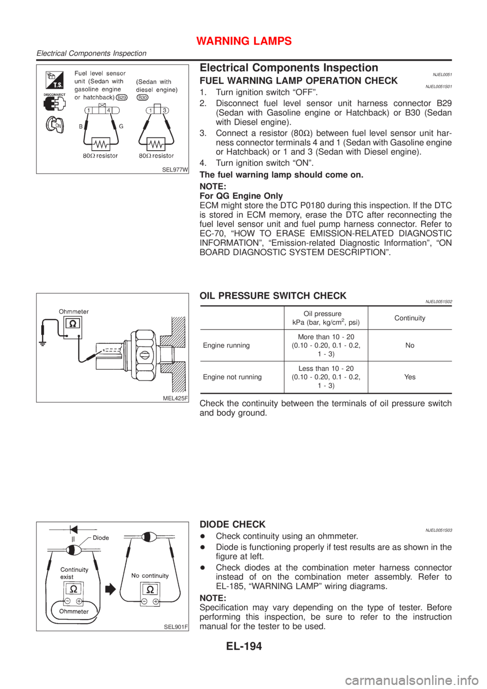
Electrical Components InspectionNJEL0051FUEL WARNING LAMP OPERATION CHECKNJEL0051S011. Turn ignition switch ªOFFº.
2. Disconnect fuel level sensor unit harness connector B29
(Sedan with Gasoline engine or Hatchback) or B30 (Sedan
with Diesel engine).
3. Connect a resistor (80W) between fuel level sensor unit har-
ness connector terminals 4 and 1 (Sedan with Gasoline engine
or Hatchback) or 1 and 3 (Sedan with Diesel engine).
4. Turn ignition switch ªONº.
The fuel warning lamp should come on.
NOTE:
For QG Engine Only
ECM might store the DTC P0180 during this inspection. If the DTC
is stored in ECM memory, erase the DTC after reconnecting the
fuel level sensor unit and fuel pump harness connector. Refer to
EC-70, ªHOW TO ERASE EMISSION-RELATED DIAGNOSTIC
INFORMATIONº, ªEmission-related Diagnostic Informationº, ªON
BOARD DIAGNOSTIC SYSTEM DESCRIPTIONº.
MEL425F
OIL PRESSURE SWITCH CHECKNJEL0051S02
Oil pressure
kPa (bar, kg/cm2, psi)Continuity
Engine runningMore than 10 - 20
(0.10 - 0.20, 0.1 - 0.2,
1-3)No
Engine not runningLess than 10 - 20
(0.10 - 0.20, 0.1 - 0.2,
1-3)Ye s
Check the continuity between the terminals of oil pressure switch
and body ground.
SEL901F
DIODE CHECKNJEL0051S03+Check continuity using an ohmmeter.
+Diode is functioning properly if test results are as shown in the
figure at left.
+Check diodes at the combination meter harness connector
instead of on the combination meter assembly. Refer to
EL-185, ªWARNING LAMPº wiring diagrams.
NOTE:
Specification may vary depending on the type of tester. Before
performing this inspection, be sure to refer to the instruction
manual for the tester to be used.
WARNING LAMPS
Electrical Components Inspection
EL-194
Page 1758 of 2898
Trouble Diagnoses/SedanNJEL0374SYMPTOM CHARTNJEL0374S01
REFERENCE PAGE (EL- ) 200 201 202 203 204
SYMPTOM
POWER SUPPLY AND
GROUND CIRCUIT CHECK
DIAGNOSTIC PROCEDURE 1
(LIGHTING SWITCH INPUT
SIGNAL CHECK)
DIAGNOSTIC PROCEDURE 2
(KEY SWITCH INSERT
SIGNAL CHECK)
DIAGNOSTIC PROCEDURE 3
(DOOR UNLOCK SENSOR CHECK)
DIAGNOSTIC PROCEDURE 4
Light warning chime does not acti-
vate.XX X
Ignition key warning chime does not
activate.XXXX
All warning chimes do not activate. XX
POWER SUPPLY AND GROUND CIRCUIT CHECKNJEL0374S02Power Supply Circuit CheckNJEL0374S0201
SEL991W
Ground Circuit CheckNJEL0374S0202
SEL992W
WARNING CHIME
Trouble Diagnoses/Sedan
EL-200
Page 1761 of 2898
DIAGNOSTIC PROCEDURE 3 (DOOR UNLOCK SENSOR
CHECK)
NJEL0374S08
1 CHECK DOOR UNLOCK SENSOR INPUT SIGNAL
Check voltage between time control unit terminal 28 and ground.
SEL987W
OK or NG
OK©Door unlock sensor is OK.
NG©GO TO 2.
2 CHECK DOOR UNLOCK SENSOR
1. Disconnect door unlock sensor connector.
2. Check continuity between door unlock sensor terminals 2 and 5.
SEL988W
OK or NG
OK©Check the following.
+Door unlock sensor ground circuit
+Harness for open or short between time control unit and door unlock sensor
NG©Replace door unlock sensor.
WARNING CHIME
Trouble Diagnoses/Sedan (Cont'd)
EL-203
Page 1767 of 2898
Trouble Diagnoses/HatchbackNJEL0455SYMPTOM CHARTNJEL0455S01
REFERENCE PAGE (EL- ) 209 210 211 212 213
SYMPTOM
POWER SUPPLY AND
GROUND CIRCUIT CHECK
DIAGNOSTIC PROCEDURE 1
(LIGHTING SWITCH INPUT
SIGNAL CHECK)
DIAGNOSTIC PROCEDURE 2
(KEY SWITCH INSERT
SIGNAL CHECK)
DIAGNOSTIC PROCEDURE 3
(DOOR UNLOCK SENSOR CHECK)
DIAGNOSTIC PROCEDURE 4
Light warning chime does not acti-
vate.XX X
Ignition key warning chime does not
activate.XXXX
All warning chimes do not activate. XX
POWER SUPPLY AND GROUND CIRCUIT CHECKNJEL0455S02Power Supply Circuit CheckNJEL0455S0201
SEL447X
Ground Circuit CheckNJEL0455S0202
SEL448X
WARNING CHIME
Trouble Diagnoses/Hatchback
EL-209
Page 1770 of 2898
DIAGNOSTIC PROCEDURE 3 (DOOR UNLOCK SENSOR
CHECK)
NJEL0455S05
1 CHECK DOOR UNLOCK SENSOR INPUT SIGNAL
Check voltage between time control unit terminal 35 and ground.
SEL431X
OK or NG
OK©Door unlock sensor is OK.
NG©GO TO 2.
2 CHECK DOOR UNLOCK SENSOR
1. Disconnect door unlock sensor connector.
2. Check continuity between door unlock sensor terminals 2 and 5.
SEL988W
OK or NG
OK©Check the following.
+Door unlock sensor ground circuit
+Harness for open or short between time control unit and door unlock sensor
NG©Replace door unlock sensor.
WARNING CHIME
Trouble Diagnoses/Hatchback (Cont'd)
EL-212
Page 1817 of 2898

carried out. Subsequently, when the repaired audio unit is delivered to the final user again, it will be in the
ªNEWº state as to enable re-linking the audio unit to the vehicle's immobiliser system. As a result of the above,
repair of the audio unit can only be done by an authorized Clarion representative.
SPEED DEPENDENT VOLUME CONTROLNJEL0381S06DescriptionNJEL0381S0601If activated, the radio output volume will be automatically adjusted to compensate for increasing driving noises
at higher driving speeds.
The radio receives a speed signal from the vehicle speed sensor (VSS) and selects the output volume.
PERSONAL AUDIO SETTINGSNJEL0381S07DescriptionNJEL0381S0701The radio is designed to store several settings (volume, bass, treble, preset stations and level of speed
dependent volume control) with every NATS ignition key used. Up to a maximum of 4 NATS keys can be reg-
istered. During the communication as mentioned under ªAnti-Theft Systemº, the radio will recognize the used
ignition key and select the accompanying settings.
AUDIO
System Description/Sedan (Cont'd)
EL-259
Page 1828 of 2898

carried out. Subsequently, when the repaired audio unit is delivered to the final user again, it will be in the
ªNEWº state as to enable re-linking the audio unit to the vehicle's immobiliser system. As a result of the above,
repair of the audio unit can only be done by an authorized Clarion representative.
SPEED DEPENDENT VOLUME CONTROLNJEL0497S02DescriptionNJEL0497S0201If activated, the radio output volume will be automatically adjusted to compensate for increasing driving noises
at higher driving speeds.
The radio receives a speed signal from the vehicle speed sensor (VSS) and selects the output volume.
PERSONAL AUDIO SETTINGSNJEL0497S03DescriptionNJEL0497S0301The radio is designed to store several settings (volume, bass, treble, preset stations and level of speed
dependent volume control) with every NATS ignition key used. Up to a maximum of 4 NATS keys can be reg-
istered. During the communication as mentioned under ªNATS audio linkº, the radio will recognize the used
ignition key and select the accompanying settings.
AUDIO
System Description/Hatchback (Cont'd)
EL-270