Page 1290 of 2898
8 CHECK FUEL PUMP RELAY
Refer to ªComponent Inspectionº, EC-566.
OK or NG
OK©GO TO 9.
NG©Replace fuel pump relay.
9 CHECK FUEL PUMP
Refer to ªComponent Inspectionº, EC-566.
OK or NG
OK©GO TO 10.
NG©Replace fuel pump.
10 CHECK INTERMITTENT INCIDENT
Perform ªTROUBLE DIAGNOSIS FOR INTERMITTENT INCIDENTº, EC-177.
©INSPECTION END
SEF145X
Component InspectionNJEC0449FUEL PUMP RELAYNJEC0449S01Check continuity between terminals 3 and 5.
Conditions Continuity
12V direct current supply between terminals 1 and 2 Yes
No current supply No
If NG, replace relay.
JEF136Y
FUEL PUMPNJEC0449S021. Disconnect fuel level sensor unit and fuel pump harness con-
nector.
2. Check resistance between terminals 3 and 5.
Resistance: 0.2 - 5.0W[at 25ÉC (77ÉF)]
If NG, replace fuel pump.
FUEL PUMPQG
Diagnostic Procedure (Cont'd)
EC-566
Page 1309 of 2898
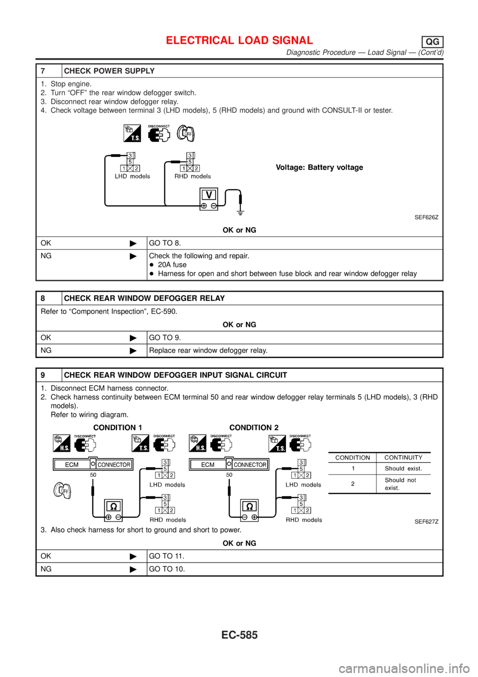
7 CHECK POWER SUPPLY
1. Stop engine.
2. Turn ªOFFº the rear window defogger switch.
3. Disconnect rear window defogger relay.
4. Check voltage between terminal 3 (LHD models), 5 (RHD models) and ground with CONSULT-II or tester.
SEF626Z
OK or NG
OK©GO TO 8.
NG©Check the following and repair.
+20A fuse
+Harness for open and short between fuse block and rear window defogger relay
8 CHECK REAR WINDOW DEFOGGER RELAY
Refer to ªComponent Inspectionº, EC-590.
OK or NG
OK©GO TO 9.
NG©Replace rear window defogger relay.
9 CHECK REAR WINDOW DEFOGGER INPUT SIGNAL CIRCUIT
1. Disconnect ECM harness connector.
2. Check harness continuity between ECM terminal 50 and rear window defogger relay terminals 5 (LHD models), 3 (RHD
models).
Refer to wiring diagram.
SEF627Z
3. Also check harness for short to ground and short to power.
OK or NG
OK©GO TO 11.
NG©GO TO 10.
ELECTRICAL LOAD SIGNALQG
Diagnostic Procedure Ð Load Signal Ð (Cont'd)
EC-585
Page 1312 of 2898
19 DETECT MALFUNCTIONING PART
Check the following.
+Harness connectors M63, F102
+Harness connectors M79, E118
+Diode M110
+Joint connector-2
+Harness for open and short between ECM and lighting switch connector
©Repair open circuit or short to ground or short to power in harness or connectors.
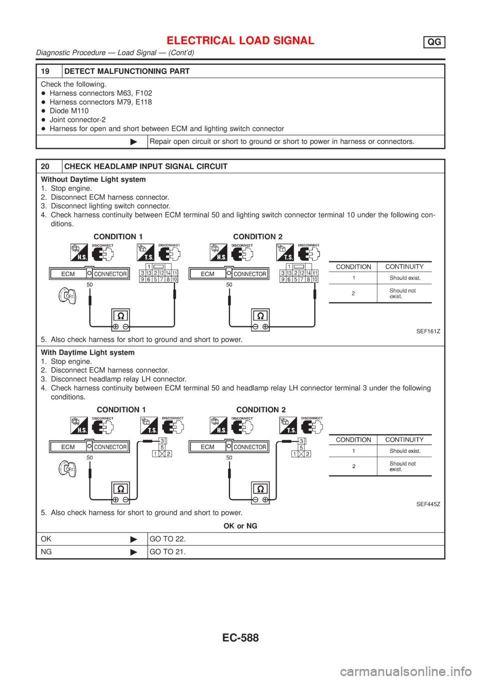
20 CHECK HEADLAMP INPUT SIGNAL CIRCUIT
Without Daytime Light system
1. Stop engine.
2. Disconnect ECM harness connector.
3. Disconnect lighting switch connector.
4. Check harness continuity between ECM terminal 50 and lighting switch connector terminal 10 under the following con-
ditions.
SEF161Z
5. Also check harness for short to ground and short to power.
With Daytime Light system
1. Stop engine.
2. Disconnect ECM harness connector.
3. Disconnect headlamp relay LH connector.
4. Check harness continuity between ECM terminal 50 and headlamp relay LH connector terminal 3 under the following
conditions.
SEF445Z
5. Also check harness for short to ground and short to power.
OK or NG
OK©GO TO 22.
NG©GO TO 21.
ELECTRICAL LOAD SIGNALQG
Diagnostic Procedure Ð Load Signal Ð (Cont'd)
EC-588
Page 1314 of 2898
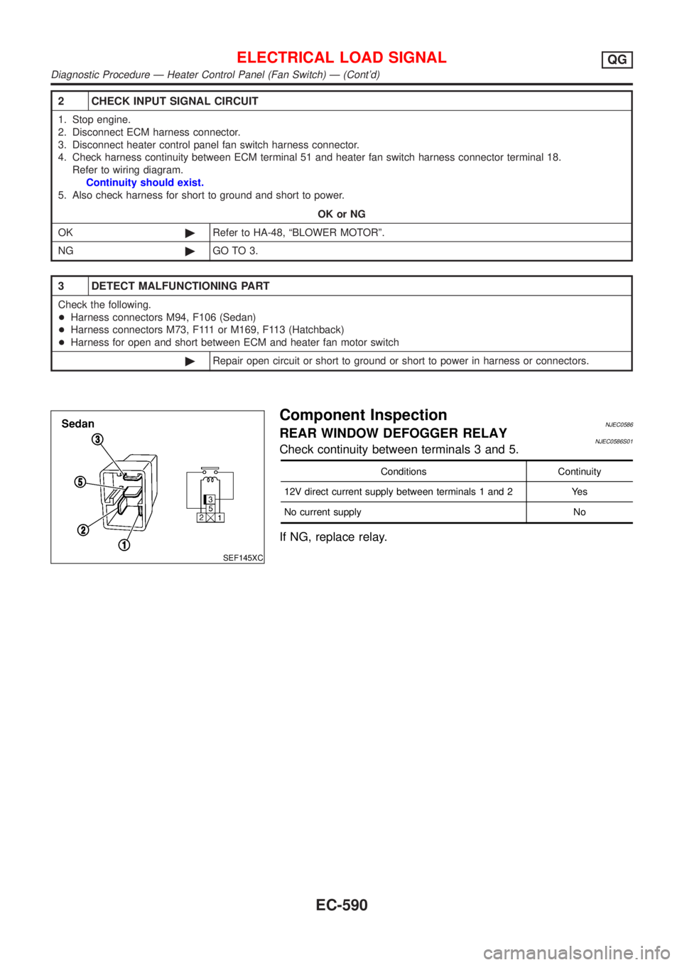
2 CHECK INPUT SIGNAL CIRCUIT
1. Stop engine.
2. Disconnect ECM harness connector.
3. Disconnect heater control panel fan switch harness connector.
4. Check harness continuity between ECM terminal 51 and heater fan switch harness connector terminal 18.
Refer to wiring diagram.
Continuity should exist.
5. Also check harness for short to ground and short to power.
OK or NG
OK©Refer to HA-48, ªBLOWER MOTORº.
NG©GO TO 3.
3 DETECT MALFUNCTIONING PART
Check the following.
+Harness connectors M94, F106 (Sedan)
+Harness connectors M73, F111 or M169, F113 (Hatchback)
+Harness for open and short between ECM and heater fan motor switch
©Repair open circuit or short to ground or short to power in harness or connectors.
SEF145XC
Component InspectionNJEC0586REAR WINDOW DEFOGGER RELAYNJEC0586S01Check continuity between terminals 3 and 5.
Conditions Continuity
12V direct current supply between terminals 1 and 2 Yes
No current supply No
If NG, replace relay.
ELECTRICAL LOAD SIGNALQG
Diagnostic Procedure Ð Heater Control Panel (Fan Switch) Ð (Cont'd)
EC-590
Page 1333 of 2898
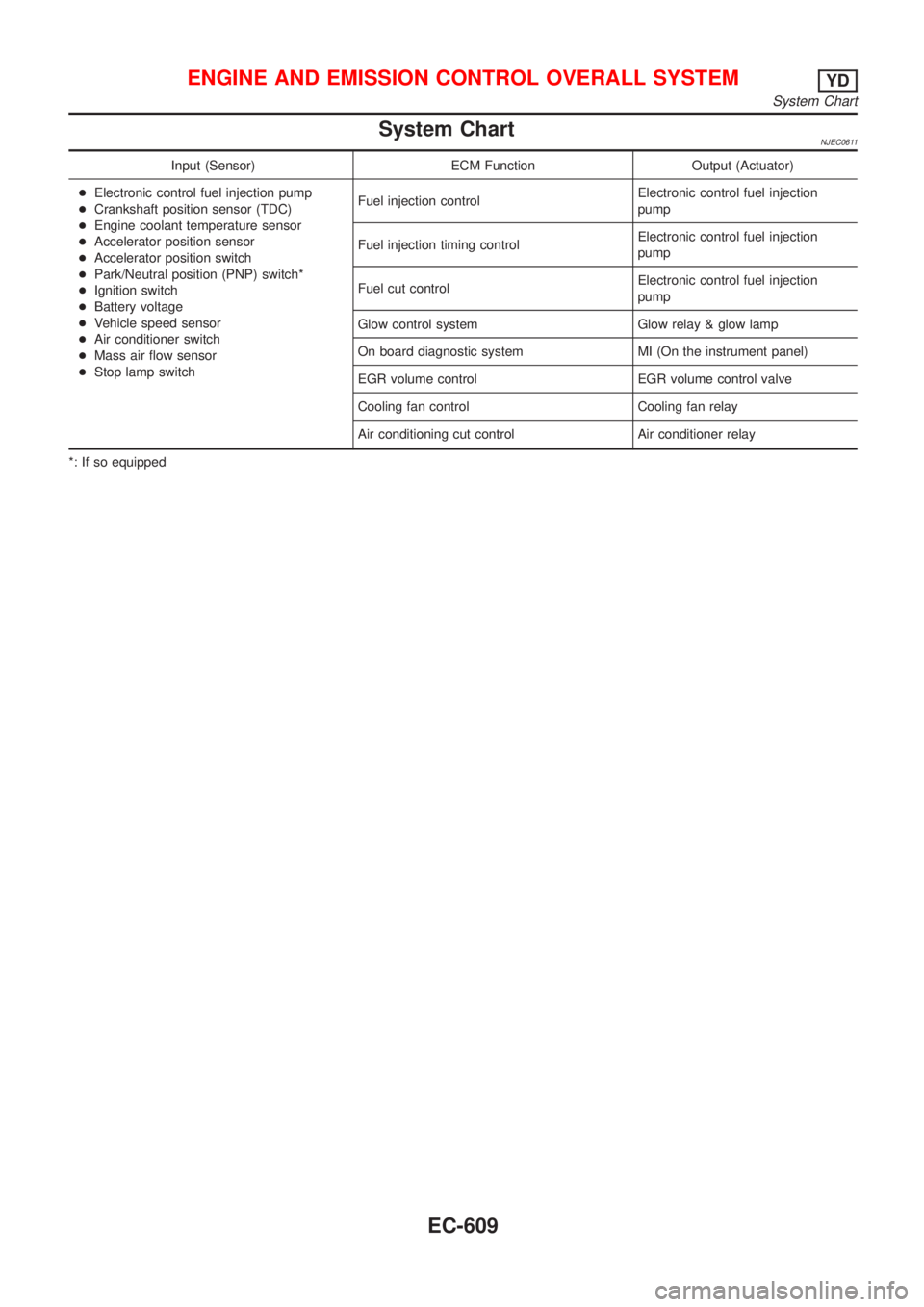
System ChartNJEC0611
Input (Sensor) ECM Function Output (Actuator)
+Electronic control fuel injection pump
+Crankshaft position sensor (TDC)
+Engine coolant temperature sensor
+Accelerator position sensor
+Accelerator position switch
+Park/Neutral position (PNP) switch*
+Ignition switch
+Battery voltage
+Vehicle speed sensor
+Air conditioner switch
+Mass air flow sensor
+Stop lamp switchFuel injection controlElectronic control fuel injection
pump
Fuel injection timing controlElectronic control fuel injection
pump
Fuel cut controlElectronic control fuel injection
pump
Glow control system Glow relay & glow lamp
On board diagnostic system MI (On the instrument panel)
EGR volume control EGR volume control valve
Cooling fan control Cooling fan relay
Air conditioning cut control Air conditioner relay
*: If so equipped
ENGINE AND EMISSION CONTROL OVERALL SYSTEMYD
System Chart
EC-609
Page 1336 of 2898
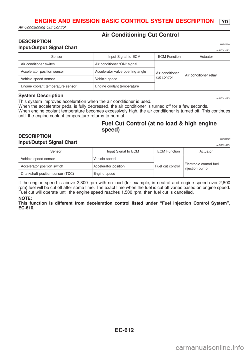
Air Conditioning Cut Control
DESCRIPTIONNJEC0614Input/Output Signal ChartNJEC0614S01
Sensor Input Signal to ECM ECM Function Actuator
Air conditioner switch Air conditioner ªONº signal
Air conditioner
cut controlAir conditioner relay Accelerator position sensor Accelerator valve opening angle
Vehicle speed sensor Vehicle speed
Engine coolant temperature sensor Engine coolant temperature
System DescriptionNJEC0614S02This system improves acceleration when the air conditioner is used.
When the accelerator pedal is fully depressed, the air conditioner is turned off for a few seconds.
When engine coolant temperature becomes excessively high, the air conditioner is turned off. This continues
until the engine coolant temperature returns to normal.
Fuel Cut Control (at no load & high engine
speed)
DESCRIPTIONNJEC0615Input/Output Signal ChartNJEC0615S01
Sensor Input Signal to ECM ECM Function Actuator
Vehicle speed sensor Vehicle speed
Fuel cut controlElectronic control fuel
injection pump Accelerator position switch Accelerator position
Crankshaft position sensor (TDC) Engine speed
If the engine speed is above 2,800 rpm with no load (for example, in neutral and engine speed over 2,800
rpm) fuel will be cut off after some time. The exact time when the fuel is cut off varies based on engine speed.
Fuel cut will operate until the engine speed reaches 1,500 rpm, then fuel cut is cancelled.
NOTE:
This function is different from deceleration control listed under ªFuel Injection Control Systemº,
EC-610.
ENGINE AND EMISSION BASIC CONTROL SYSTEM DESCRIPTIONYD
Air Conditioning Cut Control
EC-612
Page 1357 of 2898
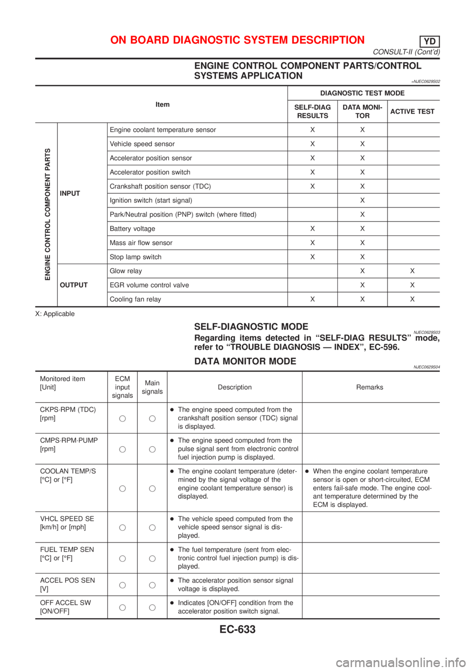
ENGINE CONTROL COMPONENT PARTS/CONTROL
SYSTEMS APPLICATION
=NJEC0629S02
ItemDIAGNOSTIC TEST MODE
SELF-DIAG
RESULTSDATA MONI-
TORACTIVE TEST
ENGINE CONTROL COMPONENT PARTS
INPUTEngine coolant temperature sensor X X
Vehicle speed sensor X X
Accelerator position sensor X X
Accelerator position switch X X
Crankshaft position sensor (TDC) X X
Ignition switch (start signal) X
Park/Neutral position (PNP) switch (where fitted) X
Battery voltage X X
Mass air flow sensor X X
Stop lamp switch X X
OUTPUTGlow relayXX
EGR volume control valve X X
Cooling fan relay X X X
X: Applicable
SELF-DIAGNOSTIC MODENJEC0629S03Regarding items detected in ªSELF-DIAG RESULTSº mode,
refer to ªTROUBLE DIAGNOSIS Ð INDEXº, EC-596.
DATA MONITOR MODENJEC0629S04
Monitored item
[Unit]ECM
input
signalsMain
signalsDescription Remarks
CKPS´RPM (TDC)
[rpm]jj+The engine speed computed from the
crankshaft position sensor (TDC) signal
is displayed.
CMPS´RPM´PUMP
[rpm]jj+The engine speed computed from the
pulse signal sent from electronic control
fuel injection pump is displayed.
COOLAN TEMP/S
[ÉC] or [ÉF]
jj+The engine coolant temperature (deter-
mined by the signal voltage of the
engine coolant temperature sensor) is
displayed.+When the engine coolant temperature
sensor is open or short-circuited, ECM
enters fail-safe mode. The engine cool-
ant temperature determined by the
ECM is displayed.
VHCL SPEED SE
[km/h] or [mph]jj+The vehicle speed computed from the
vehicle speed sensor signal is dis-
played.
FUEL TEMP SEN
[ÉC] or [ÉF]jj+The fuel temperature (sent from elec-
tronic control fuel injection pump) is dis-
played.
ACCEL POS SEN
[V]jj+The accelerator position sensor signal
voltage is displayed.
OFF ACCEL SW
[ON/OFF]jj+Indicates [ON/OFF] condition from the
accelerator position switch signal.
ON BOARD DIAGNOSTIC SYSTEM DESCRIPTIONYD
CONSULT-II (Cont'd)
EC-633
Page 1358 of 2898

Monitored item
[Unit]ECM
input
signalsMain
signalsDescription Remarks
SPILL/V [ÉCA]
j+The control position of spill valve (sent
from electronic control fuel injection
pump) is displayed.
BATTERY VOLT [V]
jj+The power supply voltage of ECM is
displayed.
P/N POSI SW*1
[ON/OFF] (where
fitted)jj+Indicates [ON/OFF] condition from the
park/neutral position switch signal.
START SIGNAL
[ON/OFF]jj+Indicates [ON/OFF] condition from the
starter signal.+After starting the engine, [OFF] is dis-
played regardless of the starter signal.
BRAKE SW
[ON/OFF]jj+Indicates [ON/OFF] condition from the
stop lamp switch signal.
BRAKE SW2
[ON/OFF]jj+Indicates [ON/OFF] condition from the
brake pedal position switch signal.
IGN SW
[ON/OFF]jj+Indicates [ON/OFF] condition from igni-
tion switch signal.
MAS AIR/FL SE [V]
jj+The signal voltage of the mass air flow
sensor is displayed.+When the engine is stopped, a certain
value is indicated.
INT/A VOLUME [mg/]+The intake air volume computed from
the mass air flow sensor signal is dis-
played.
F/CUT SIGNAL
[ON/OFF]
j+The [ON/OFF] condition from decelera-
tion fuel cut signal (sent from electronic
control fuel injection pump) is displayed.
OFF´´´Fuel is cut off.
ON´´´Fuel is not cut off.
GLOW RLY
[ON/OFF]j+The glow relay control condition (deter-
mined by ECM according to the input
signal) is displayed.
COOLING FAN
[LOW/HI/OFF]
j+Indicates the control condition of the
cooling fans (determined by ECM
according to the input signal).
+LOW ... Operates at low speed.
HI ... Operates at high speed.
OFF ... Stopped.
BARO SEN [kPa]
jj+The barometric pressure (determined
by the signal voltage from the baromet-
ric pressure sensor built into the ECM)
is displayed.
EGR VOL CON/V
[step]
j+Indicates the EGR volume control value
computed by the ECM according to the
input signals.
+The opening becomes larger as the
value increases.
*1: On models not equipped with park/neutral position (PNP) switch, ªOFFº is always displayed regardless of gear shift position.
NOTE:
Any monitored item that does not match the vehicle being diagnosed is deleted from the display automatically.
ON BOARD DIAGNOSTIC SYSTEM DESCRIPTIONYD
CONSULT-II (Cont'd)
EC-634