Page 1401 of 2898
Diagnostic ProcedureNJEC0648
1 CHECK MAFS POWER SUPPLY CIRCUIT
1. Turn ignition switch ªOFFº.
2. Disconnect mass air flow sensor harness connector.
SEF884Y
3. Turn ignition switch ªONº.
4. Check voltage between mass air flow sensor terminals 2, 4 and ground with CONSULT-II or tester.
SEF297X
OK or NG
OK©GO TO 3.
NG©GO TO 2.
2 DETECT MALFUNCTIONING PART
Check the following.
+Harness connectors E75, F36 (Sedan models and hatchback models with ecm in engine compartment)
+Harness for open or short between mass air flow sensor and ECM
+Harness for open or short between mass air flow sensor and ECM relay
©Repair open circuit or short to ground or short to power in harness or connector.
DTC P0100 MASS AIR FLOW SENYD
Diagnostic Procedure
EC-677
Page 1436 of 2898
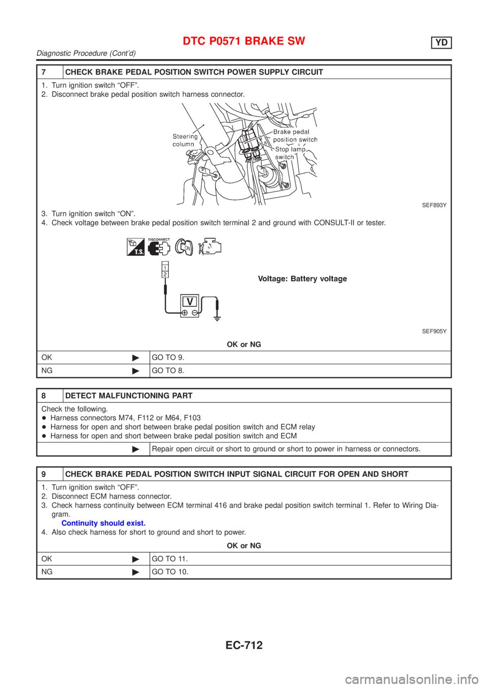
7 CHECK BRAKE PEDAL POSITION SWITCH POWER SUPPLY CIRCUIT
1. Turn ignition switch ªOFFº.
2. Disconnect brake pedal position switch harness connector.
SEF893Y
3. Turn ignition switch ªONº.
4. Check voltage between brake pedal position switch terminal 2 and ground with CONSULT-II or tester.
SEF905Y
OK or NG
OK©GO TO 9.
NG©GO TO 8.
8 DETECT MALFUNCTIONING PART
Check the following.
+Harness connectors M74, F112 or M64, F103
+Harness for open and short between brake pedal position switch and ECM relay
+Harness for open and short between brake pedal position switch and ECM
©Repair open circuit or short to ground or short to power in harness or connectors.
9 CHECK BRAKE PEDAL POSITION SWITCH INPUT SIGNAL CIRCUIT FOR OPEN AND SHORT
1. Turn ignition switch ªOFFº.
2. Disconnect ECM harness connector.
3. Check harness continuity between ECM terminal 416 and brake pedal position switch terminal 1. Refer to Wiring Dia-
gram.
Continuity should exist.
4. Also check harness for short to ground and short to power.
OK or NG
OK©GO TO 11.
NG©GO TO 10.
DTC P0571 BRAKE SWYD
Diagnostic Procedure (Cont'd)
EC-712
Page 1445 of 2898
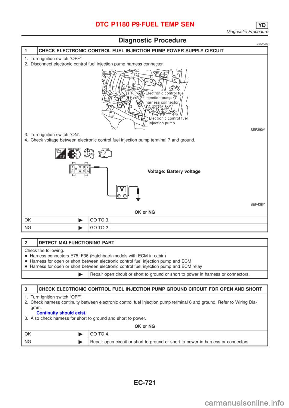
Diagnostic ProcedureNJEC0678
1 CHECK ELECTRONIC CONTROL FUEL INJECTION PUMP POWER SUPPLY CIRCUIT
1. Turn ignition switch ªOFFº.
2. Disconnect electronic control fuel injection pump harness connector.
SEF390Y
3. Turn ignition switch ªONº.
4. Check voltage between electronic control fuel injection pump terminal 7 and ground.
SEF438Y
OK or NG
OK©GO TO 3.
NG©GO TO 2.
2 DETECT MALFUNCTIONING PART
Check the following.
+Harness connectors E75, F36 (Hatchback models with ECM in cabin)
+Harness for open or short between electronic control fuel injection pump and ECM
+Harness for open or short between electronic control fuel injection pump and ECM relay
©Repair open circuit or short to ground or short to power in harness or connectors.
3 CHECK ELECTRONIC CONTROL FUEL INJECTION PUMP GROUND CIRCUIT FOR OPEN AND SHORT
1. Turn ignition switch ªOFFº.
2. Check harness continuity between electronic control fuel injection pump terminal 6 and ground. Refer to Wiring Dia-
gram.
Continuity should exist.
3. Also check harness for short to ground and short to power.
OK or NG
OK©GO TO 4.
NG©Repair open circuit or short to ground or short to power in harness or connectors.
DTC P1180 P9´FUEL TEMP SENYD
Diagnostic Procedure
EC-721
Page 1452 of 2898
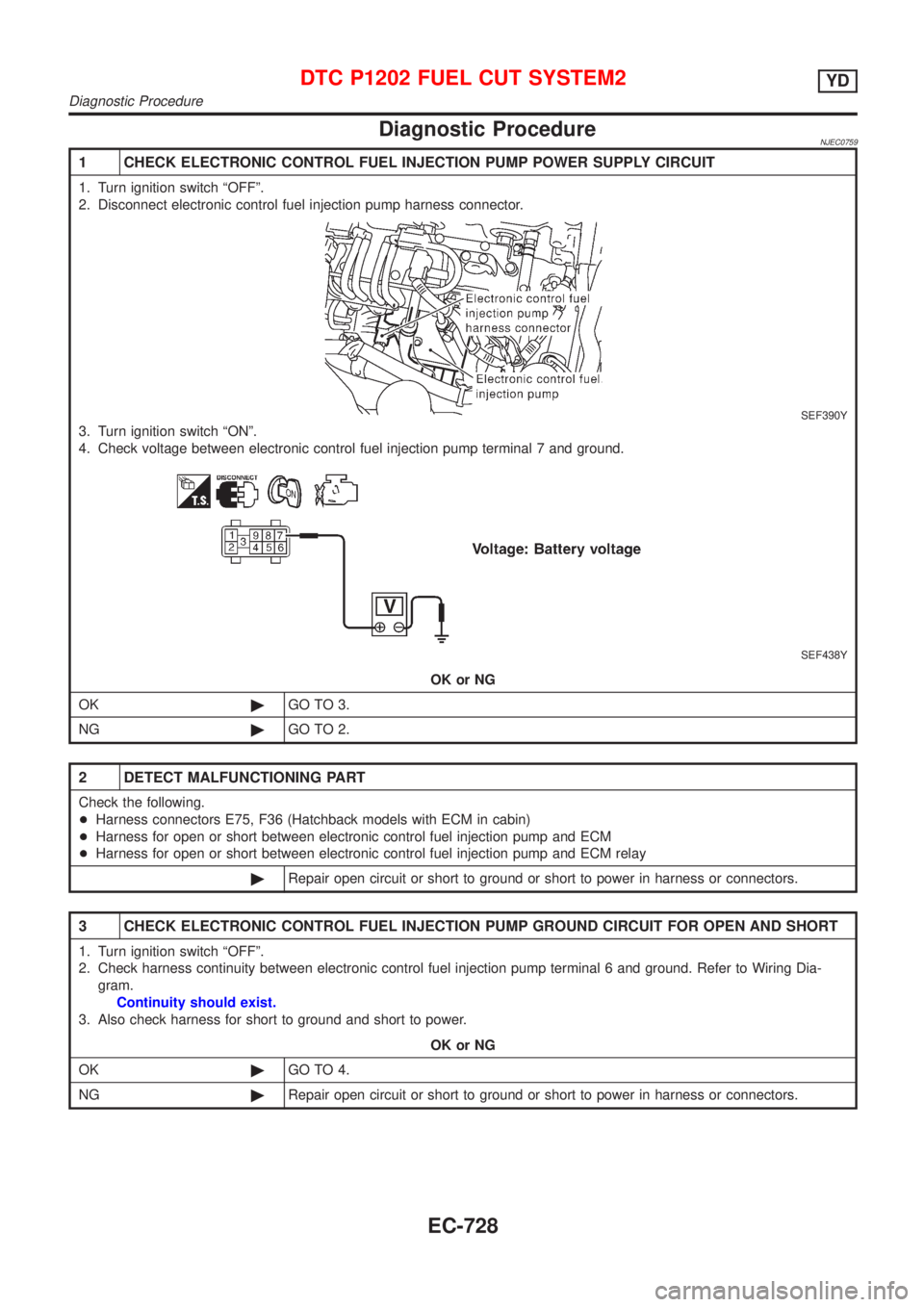
Diagnostic ProcedureNJEC0759
1 CHECK ELECTRONIC CONTROL FUEL INJECTION PUMP POWER SUPPLY CIRCUIT
1. Turn ignition switch ªOFFº.
2. Disconnect electronic control fuel injection pump harness connector.
SEF390Y
3. Turn ignition switch ªONº.
4. Check voltage between electronic control fuel injection pump terminal 7 and ground.
SEF438Y
OK or NG
OK©GO TO 3.
NG©GO TO 2.
2 DETECT MALFUNCTIONING PART
Check the following.
+Harness connectors E75, F36 (Hatchback models with ECM in cabin)
+Harness for open or short between electronic control fuel injection pump and ECM
+Harness for open or short between electronic control fuel injection pump and ECM relay
©Repair open circuit or short to ground or short to power in harness or connectors.
3 CHECK ELECTRONIC CONTROL FUEL INJECTION PUMP GROUND CIRCUIT FOR OPEN AND SHORT
1. Turn ignition switch ªOFFº.
2. Check harness continuity between electronic control fuel injection pump terminal 6 and ground. Refer to Wiring Dia-
gram.
Continuity should exist.
3. Also check harness for short to ground and short to power.
OK or NG
OK©GO TO 4.
NG©Repair open circuit or short to ground or short to power in harness or connectors.
DTC P1202 FUEL CUT SYSTEM2YD
Diagnostic Procedure
EC-728
Page 1454 of 2898
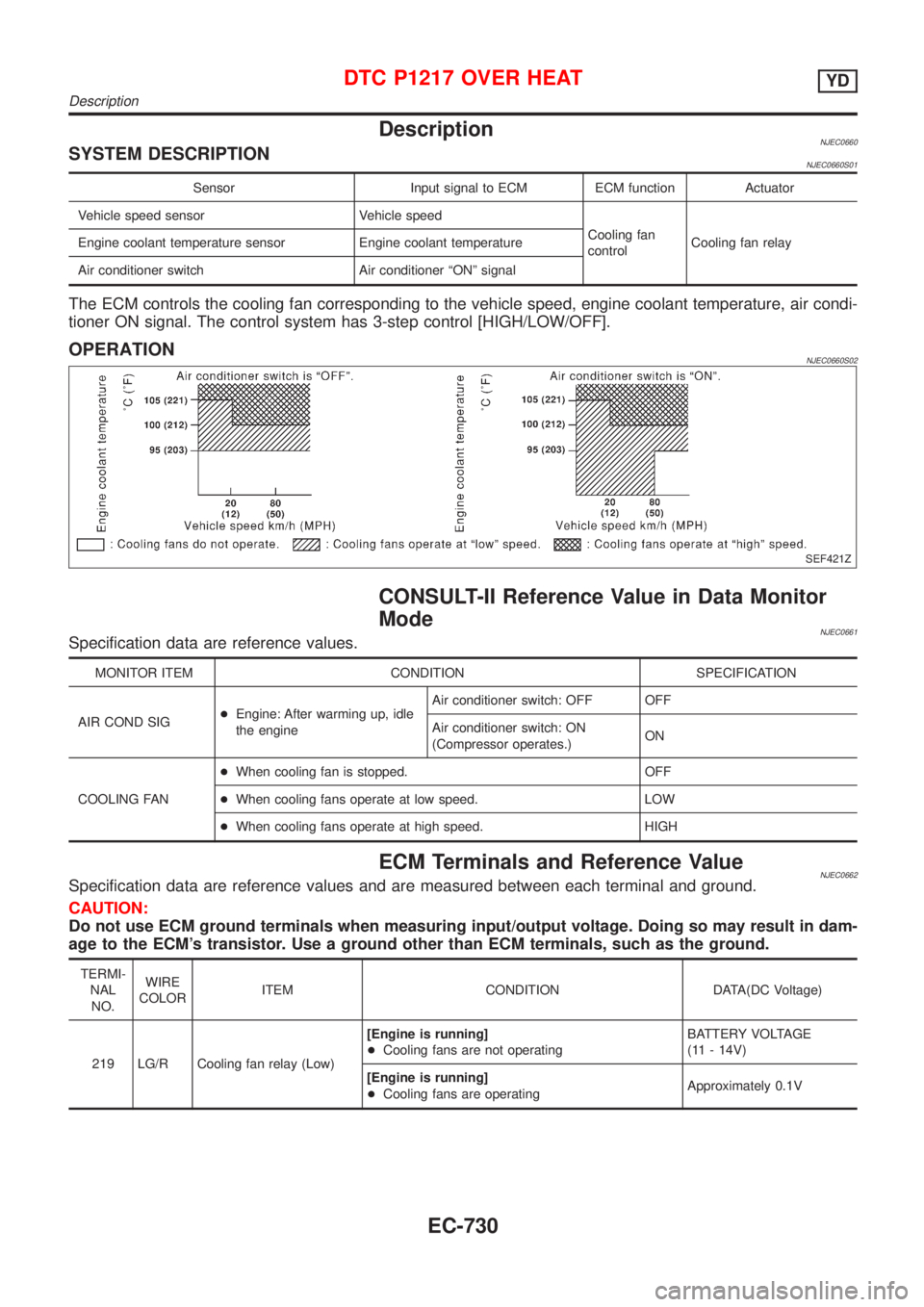
DescriptionNJEC0660SYSTEM DESCRIPTIONNJEC0660S01
Sensor Input signal to ECM ECM function Actuator
Vehicle speed sensor Vehicle speed
Cooling fan
controlCooling fan relay Engine coolant temperature sensor Engine coolant temperature
Air conditioner switch Air conditioner ªONº signal
The ECM controls the cooling fan corresponding to the vehicle speed, engine coolant temperature, air condi-
tioner ON signal. The control system has 3-step control [HIGH/LOW/OFF].
OPERATIONNJEC0660S02
SEF421Z
CONSULT-II Reference Value in Data Monitor
Mode
NJEC0661Specification data are reference values.
MONITOR ITEM CONDITION SPECIFICATION
AIR COND SIG+Engine: After warming up, idle
the engineAir conditioner switch: OFF OFF
Air conditioner switch: ON
(Compressor operates.)ON
COOLING FAN+When cooling fan is stopped. OFF
+When cooling fans operate at low speed. LOW
+When cooling fans operate at high speed. HIGH
ECM Terminals and Reference ValueNJEC0662Specification data are reference values and are measured between each terminal and ground.
CAUTION:
Do not use ECM ground terminals when measuring input/output voltage. Doing so may result in dam-
age to the ECM's transistor. Use a ground other than ECM terminals, such as the ground.
TERMI-
NAL
NO.WIRE
COLORITEM CONDITION DATA(DC Voltage)
219 LG/R Cooling fan relay (Low)[Engine is running]
+Cooling fans are not operatingBATTERY VOLTAGE
(11 - 14V)
[Engine is running]
+Cooling fans are operatingApproximately 0.1V
DTC P1217 OVER HEATYD
Description
EC-730
Page 1455 of 2898

TERMI-
NAL
NO.WIRE
COLORITEM CONDITION DATA(DC Voltage)
221 LG/B Cooling fan relay (High)[Engine is running]
+Cooling fans are not operating
+Cooling fans are operating at low speedBATTERY VOLTAGE
(11 - 14V)
[Engine is running]
+Cooling fans are operating at high speedApproximately 0.1V
On Board Diagnosis LogicNJEC0663This diagnosis continuously monitors the engine coolant temperature.
If the cooling fan or another component in the cooling system malfunctions, engine coolant temperature will
rise.
When the engine coolant temperature reaches an abnormally high temperature condition, a malfunction is
indicated.
DTC Malfunction is detected when ... Check Items (Possible Cause)
P1217
0208+Cooling fan does not operate properly (Overheat).
+Cooling fan system does not operate properly
(Overheat).
+Engine coolant was not added to the system using
the proper filling method.+Harness or connectors
(The cooling fan circuit is open or shorted.)
+Cooling fan
+Radiator hose
+Radiator
+Radiator cap
+Water pump
+Thermostat
+Engine coolant temperature sensor
For more information, refer to ªMAIN 12 CAUSES OF
OVERHEATINGº, EC-756.
CAUTION:
When a malfunction is indicated, be sure to replace the coolant following the procedure in the LC-44,
ªChanging Engine Coolantº. Also, replace the engine oil.
1) Fill radiator with coolant up to specified level with a filling speed of 2 liters per minute. Be sure
to use coolant with the proper mixture ratio. Refer to MA-18, ªEngine Coolant Mixture Ratioº.
2) After refilling coolant, run engine to ensure that no water-flow noise is emitted.
DTC P1217 OVER HEATYD
ECM Terminals and Reference Value (Cont'd)
EC-731
Page 1459 of 2898
Diagnostic ProcedureNJEC0666SEDANNJEC0666S03
1 INSPECTION START
Do you have CONSULT-II?
YesorNo
Ye s©GO TO 2.
No©GO TO 4.
2 CHECK COOLING FAN LOW SPEED OPERATION
With CONSULT-II
1. Disconnect cooling fan relays-2 and -3.
SEF384Y
2. Turn ignition switch ªONº.
3. Perform ªCOOLING FANº in ªACTIVE TESTº mode with CONSULT-II.
SEF646X
4. Make sure that cooling fans-1 and -2 operate at low speed.
OK or NG
OK©GO TO 3.
NG©Check cooling fan low speed control circuit. (Go to PROCEDURE A, EC-740.)
DTC P1217 OVER HEATYD
Diagnostic Procedure
EC-735
Page 1460 of 2898
3 CHECK COOLING FAN HIGH SPEED OPERATION
With CONSULT-II
1. Turn ignition switch ªOFFº.
2. Reconnect cooling fan relays-2 and -3.
3. Turn ignition switch ªONº.
4. Perform ªCOOLING FANº in ªACTIVE TESTº mode with CONSULT-II.
SEF111X
5. Make sure that cooling fans-1 and -2 operate at high speed.
OK or NG
OK©GO TO 6.
NG©Check cooling fan high speed control circuit. (Go to PROCEDURE B, EC-743.)
DTC P1217 OVER HEATYD
Diagnostic Procedure (Cont'd)
EC-736


